17.07.2025 2
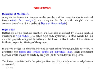
Dynamics ofMachinery
Analyses the forces and couples on the members of the machine due to external
forces (static force analysis), also analyses the forces and couples due to
accelerations of machine members ( Dynamic force analysis)
Rigid Body
Deflections of the machine members are neglected in general by treating machine
members as rigid bodies (also called rigid body dynamics). In other words the link
must be properly designed to withstand the forces without undue deformation to
facilitate proper functioning of the system.
In order to design the parts of a machine or mechanism for strength, it is necessary to
determine the forces and torques acting on individual links. Each component
however small, should be carefully analysed for its role in transmitting force.
The forces associated with the principal function of the machine are usually known
or assumed.
DEFINITIONS
17.07.2025 4
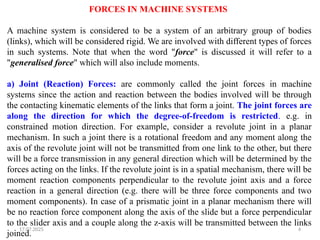
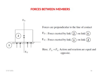
FORCES INMACHINE SYSTEMS
A machine system is considered to be a system of an arbitrary group of bodies
(links), which will be considered rigid. We are involved with different types of forces
in such systems. Note that when the word "force" is discussed it will refer to a
"generalised force" which will also include moments.
a) Joint (Reaction) Forces: are commonly called the joint forces in machine
systems since the action and reaction between the bodies involved will be through
the contacting kinematic elements of the links that form a joint. The joint forces are
along the direction for which the degree-of-freedom is restricted. e.g. in
constrained motion direction. For example, consider a revolute joint in a planar
mechanism. In such a joint there is a rotational freedom and any moment along the
axis of the revolute joint will not be transmitted from one link to the other, but there
will be a force transmission in any general direction which will be determined by the
forces acting on the links. If the revolute joint is in a spatial mechanism, there will be
moment reaction components perpendicular to the revolute joint axis and a force
reaction in a general direction (e.g. there will be three force components and two
moment components). In case of a prismatic joint in a planar mechanism there will
be no reaction force component along the axis of the slide but a force perpendicular
to the slider axis and a couple along the z-axis will be transmitted between the links
joined.
5.
17.07.2025 5
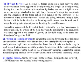
b) PhysicalForces : As the physical forces acting on a rigid body we shall
include external forces applied on the rigid body, the weight of the rigid body,
driving force, or forces that are transmitted by bodies that are not rigid such as
springs or strings attached to the rigid body. In case of springs, the magnitude
and the direction of the force acting will depend on the geometry of the
mechanism at the instant considered. In case of a string, when the string is tight,
the force will be in the direction of the string and its sense must be such that it
keeps the string in tension; otherwise the string force will be zero.
In machine systems, if the force distribution within the rigid body considered is
not our concern, the weight of the rigid body can be considered to be equivalent
to a force applied at the center of gravity of the rigid body, in the sense and
direction of the gravity field.
c) Friction or Resisting Force: In general the resisting forces are those that result
due to motion and which resist the motion. Since the rigid body assumption is
made, one can neglect the internal friction forces that will exist within the body. In
such a case friction forces are at the joints in the direction of the relative motion but
in opposite sense or in the members that are specially designed to create the friction
force (dampers). Friction forces will be discussed in more detail in coming section .
d) Inertial Forces. Are the forces due to the inertia of the rigid bodies involved.
These forces will be discussed in the coming sections.
6.
17.07.2025 6
Apart fromstatic forces, mechanism also experiences inertia forces when subjected to
acceleration, called dynamic forces.
Static forces are predominant at lower speeds and
dynamic forces are predominant at higher speeds.
Here, the analysis is aimed at determining the forces transmitted from one point to another,
essentially from input point to output point. This would be the starting point for strength
design of a component/ system, basically to decide the dimensions of the components.
Why force analysis?
Force analysis is essential to avoid either overestimation or under estimation of forces on
machine member.
Underestimation: leads to design of insufficient strength and to early failure.
Overestimation: machine component would have more strength than required.
Over design leads to heavier machines, costlier and becomes not competitive
FORCE ANALYSIS
7.
17.07.2025 7
A machine/ mechanism is a three dimensional object, with forces acting in three
dimensions.
1. For a complete force analysis, all the forces are projected on to three mutually
perpendicular planes.
2. Then, for each reference plane, it is necessary that, the vector sum of the
applied forces in zero and that, the moment of the forces about any axis
perpendicular to the reference plane or about any point in the plane is zero for
equilibrium.
General Principle of force analysis:
10
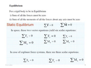
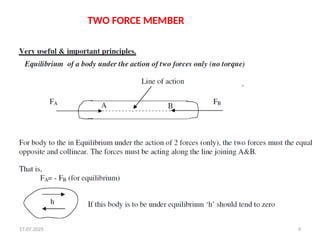
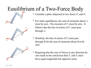
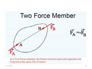
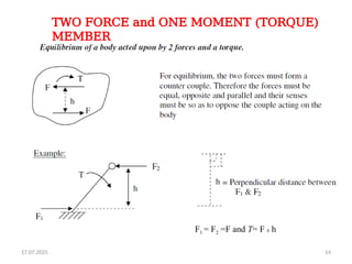
Equilibrium of aTwo-Force Body
• Consider a plate subjected to two forces F1 and F2
• For static equilibrium, the sum of moments about A
must be zero. The moment of F2 must be zero. It
follows that the line of action of F2 must pass
through A.
• Similarly, the line of action of F1 must pass
through B for the sum of moments about B to be
zero.
• Requiring that the sum of forces in any direction be
zero leads to the conclusion that F1 and F2 must
have equal magnitude but opposite sense.
17.07.2025
17.07.2025
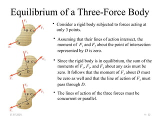
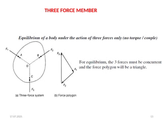
Equilibrium of aThree-Force Body
4 - 12
• Consider a rigid body subjected to forces acting at
only 3 points.
• Assuming that their lines of action intersect, the
moment of F1 and F2 about the point of intersection
represented by D is zero.
• Since the rigid body is in equilibrium, the sum of the
moments of F1, F2, and F3 about any axis must be
zero. It follows that the moment of F3 about D must
be zero as well and that the line of action of F3 must
pass through D.
• The lines of action of the three forces must be
concurrent or parallel.
17.07.2025 21
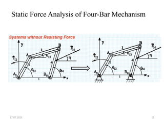
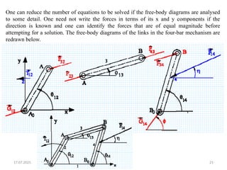
One canreduce the number of equations to be solved if the free-body diagrams are analysed
to some detail. One need not write the forces in terms of its x and y components if the
direction is known and one can identify the forces that are of equal magnitude before
attempting for a solution. The free-body diagrams of the links in the four-bar mechanism are
redrawn below.
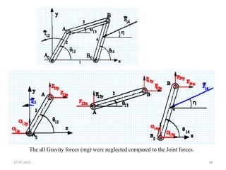
22.
22
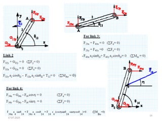
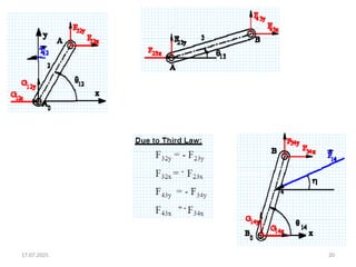
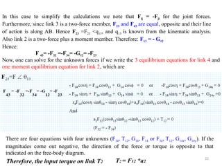
In this caseto simplify the calculations we note that Fij = -Fji for the joint forces.
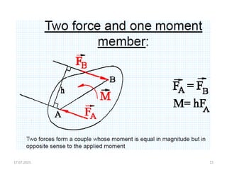
Furthermore, since link 3 is a two-force member, F23 and F43 are equal, opposite and their line
of action is along AB. Hence F23 =F23 <q13, and q13 is known from the kinematic analysis.
Also link 2 is a two-force plus a moment member. Therefore: F13 = - G12
Hence:
F 43= -F32 =-F34= -G12= -F23
Now, one can solve for the unknown forces if we write the 3 equilibrium equations for link 4 and
one moment equilibrium equation for link 2, which are
There are four equations with four unknowns (F34, T12, G14, F14 or F34, T12, G14x, G14y). If the
magnitudes come out negative, the direction of the force or torque is opposite to that
indicated on the free-body diagram.
Therefore, the input torque on link T2 T2 = F12 *a2
23.
17.07.2025 23
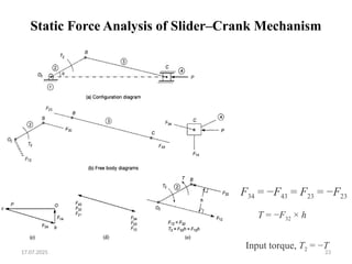
Static ForceAnalysis of Slider–Crank Mechanism
F34 = −F43 = F23 = −F23
T = −F32 × h
Input torque, T2 = −T
24.
17.07.2025 24
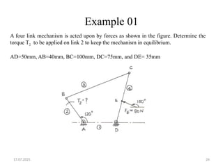
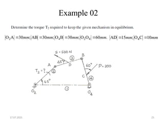
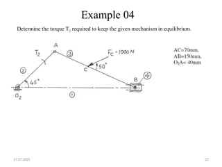
Example 01
Afour link mechanism is acted upon by forces as shown in the figure. Determine the
torque T2 to be applied on link 2 to keep the mechanism in equilibrium.
AD=50mm, AB=40mm, BC=100mm, DC=75mm, and DE= 35mm
17.07.2025 26
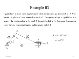
Example 03
Figureshows a slider crank mechanism in which the resultant gas pressure 8 x 10⁴
N/m2
acts on the piston of cross sectional area 0.1 m2
. The system is kept in equilibrium as a
result of the couple applied to the crank 2, through the shaft at O2. Determine forces acting
on all the links (including the pins) and the couple on link 2.
17.07.2025 28
DYNAMIC FORCEANALYSIS
Dynamic forces in mechanisms arise due to mass of the links and their
accelerations. Dynamic analysis has to be carried out when the dynamic forces
are comparable with the externally applied forces.
29.
17.07.2025 29
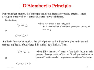
D’Alembert’s Principle
Forrectilinear motion, this principle states that inertia forces and external forces
acting on a body taken together give statically equilibrium.
Similarly for angular motion, this principle states that inertia couples and external
torques applied to a body keep it in statical equilibrium. Thus,
where m = mass of the body, and
fG = acceleration of center of gravity or (mass) of
the body.
where IG = moment of inertia of the body about an axis
passing through center of gravity G and perpendicular to
plane of rotation, and a = angular acceleration of the body.
30.
17.07.2025 30
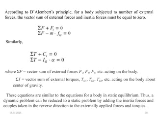
According toD’Alembert’s principle, for a body subjected to number of external
forces, the vector sum of external forces and inertia forces must be equal to zero.
Similarly,
where ΣF = vector sum of external forces F1, F2, F3, etc. acting on the body.
ΣT = vector sum of external torques, TG1, TG2, TG3, etc. acting on the body about
center of gravity.
These equations are similar to the equations for a body in static equilibrium. Thus, a
dynamic problem can be reduced to a static problem by adding the inertia forces and
couples taken in the reverse direction to the externally applied forces and torques.
31.
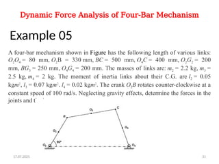
Dynamic Force Analysisof Four-Bar Mechanism
Example 05
A four-bar mechanism shown in Figure has the following length of various links:
O2O4 = 80 mm, O2B = 330 mm, BC = 500 mm, O4C = 400 mm, O2G2 = 200
mm, BG3 = 250 mm, O4G4 = 200 mm. The masses of links are: m2 = 2.2 kg, m3 =
2.5 kg, m4 = 2 kg. The moment of inertia links about their C.G. are l2 = 0.05
kgm2
, l3 = 0.07 kgm2
. l4 = 0.02 kgm2
. The crank O2B rotates counter-clockwise at a
constant speed of 100 rad/s. Neglecting gravity effects, determine the forces in the
joints and the input torque.
17.07.2025 31
32.
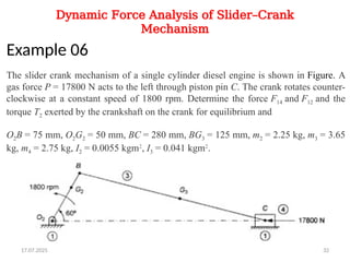
Dynamic Force Analysisof Slider–Crank
Mechanism
Example 06
The slider crank mechanism of a single cylinder diesel engine is shown in Figure. A
gas force P = 17800 N acts to the left through piston pin C. The crank rotates counter-
clockwise at a constant speed of 1800 rpm. Determine the force F14 and F12 and the
torque T2 exerted by the crankshaft on the crank for equilibrium and
O2B = 75 mm, O2G2 = 50 mm, BC = 280 mm, BG3 = 125 mm, m2 = 2.25 kg, m3 = 3.65
kg, m4 = 2.75 kg, I2 = 0.0055 kgm2
, I3 = 0.041 kgm2
.
17.07.2025 32
33.
17.07.2025 33
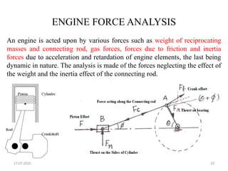
ENGINE FORCEANALYSIS
An engine is acted upon by various forces such as weight of reciprocating
masses and connecting rod, gas forces, forces due to friction and inertia
forces due to acceleration and retardation of engine elements, the last being
dynamic in nature. The analysis is made of the forces neglecting the effect of
the weight and the inertia effect of the connecting rod.
34.
17.07.2025 34
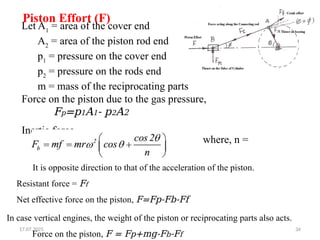
Piston Effort(F)
Let A1
= area of the cover end
A2
= area of the piston rod end
p1
= pressure on the cover end
p2
= pressure on the rods end
m = mass of the reciprocating parts
Force on the piston due to the gas pressure,
Fp=p1A1- p2A2
Inertia force,
It is opposite direction to that of the acceleration of the piston.
Resistant force = Ff
Net effective force on the piston, F=Fp-Fb-Ff
In case vertical engines, the weight of the piston or reciprocating parts also acts.
Force on the piston, F = Fp+mg-Fb-Ff
where, n =
35.
17.07.2025 35
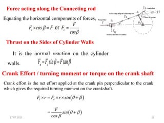
Force actingalong the Connecting rod
Equating the horizontal components of forces,
Crank effort is the net effort applied at the crank pin perpendicular to the crank
which gives the required turning moment on the crankshaft.
Thrust on the Sides of Cylinder Walls
It is the normal reaction on the cylinder
walls.
Crank Effort / turning moment or torque on the crank shaft
36.
17.07.2025 36
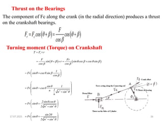
Thrust onthe Bearings
The component of Fc along the crank (in the radial direction) produces a thrust
on the crankshaft bearings.
Turning moment (Torque) on Crankshaft
37.
17.07.2025 37
Example 07
Thecrank-pin circle radius of a horizontal engine is 300 mm. The mass of the
reciprocating parts is 250 kg. When the crank has travelled 60° from I.D.C., the
difference between the driving and the back pressures is 0.35 N/mm2
. The connecting
rod length between centres is 1.2 m, and the cylinder bore is 0.5 m. If the engine runs
at 250 rpm and if the effect of piston rod diameter is neglected, calculate:
1. pressure on slide bars,
2. thrust in the connecting rod,
3. tangential force on the crank-pin, and
4. turning moment on the crank shaft.
38.
17.07.2025 38
Example 08
Avertical petrol engine 100 mm diameter and 120 mm stroke has a connecting rod 250
mm long. The mass of the piston is 1.1 kg. The speed is 2000 rpm. On the expansion
stroke with a crank 20° from top dead centre, the gas pressure is 700 KN/m2
.
Determine:
1. Net force on the piston,
2. Resultant load on the gudgeon pin,
3. Thrust on the cylinder walls, and
4. Speed above which, other things remaining same, the gudgeon pin load would be reversed
in direction.