Download to read offline
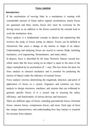


Force analysis is a fundamental tool used to understand how forces affect the motion and behavior of objects. It involves identifying all forces acting on an object, determining their magnitudes and directions, and applying Newton's laws of motion. Force analysis is used across various engineering fields to predict how structures and systems will perform under different loading conditions. It allows engineers to design structures and machines that can withstand anticipated forces safely and efficiently. Force analysis considers both static systems at rest as well as dynamic systems in motion. Computer modeling has enhanced force analysis by enabling complex systems to be simulated.