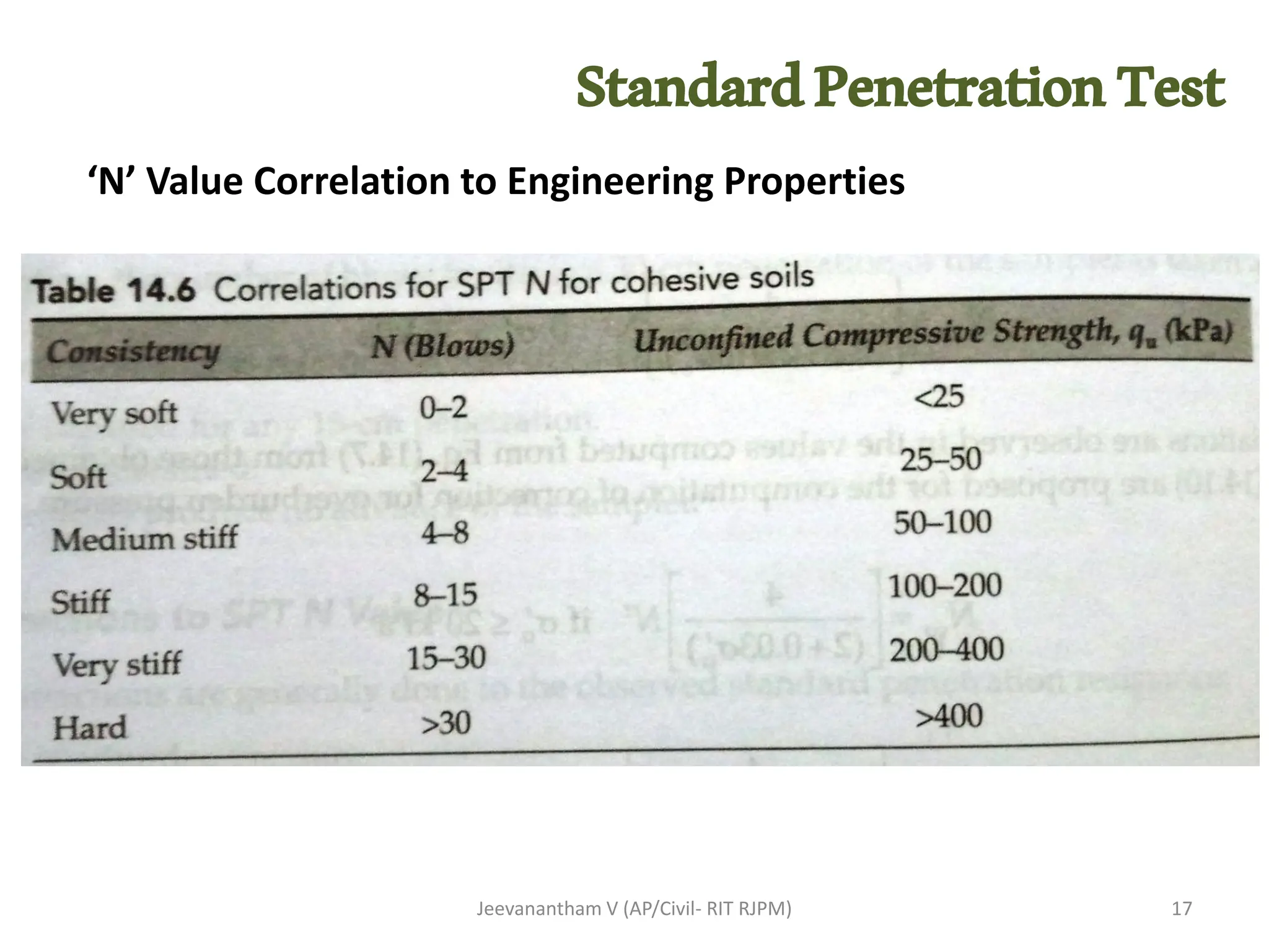
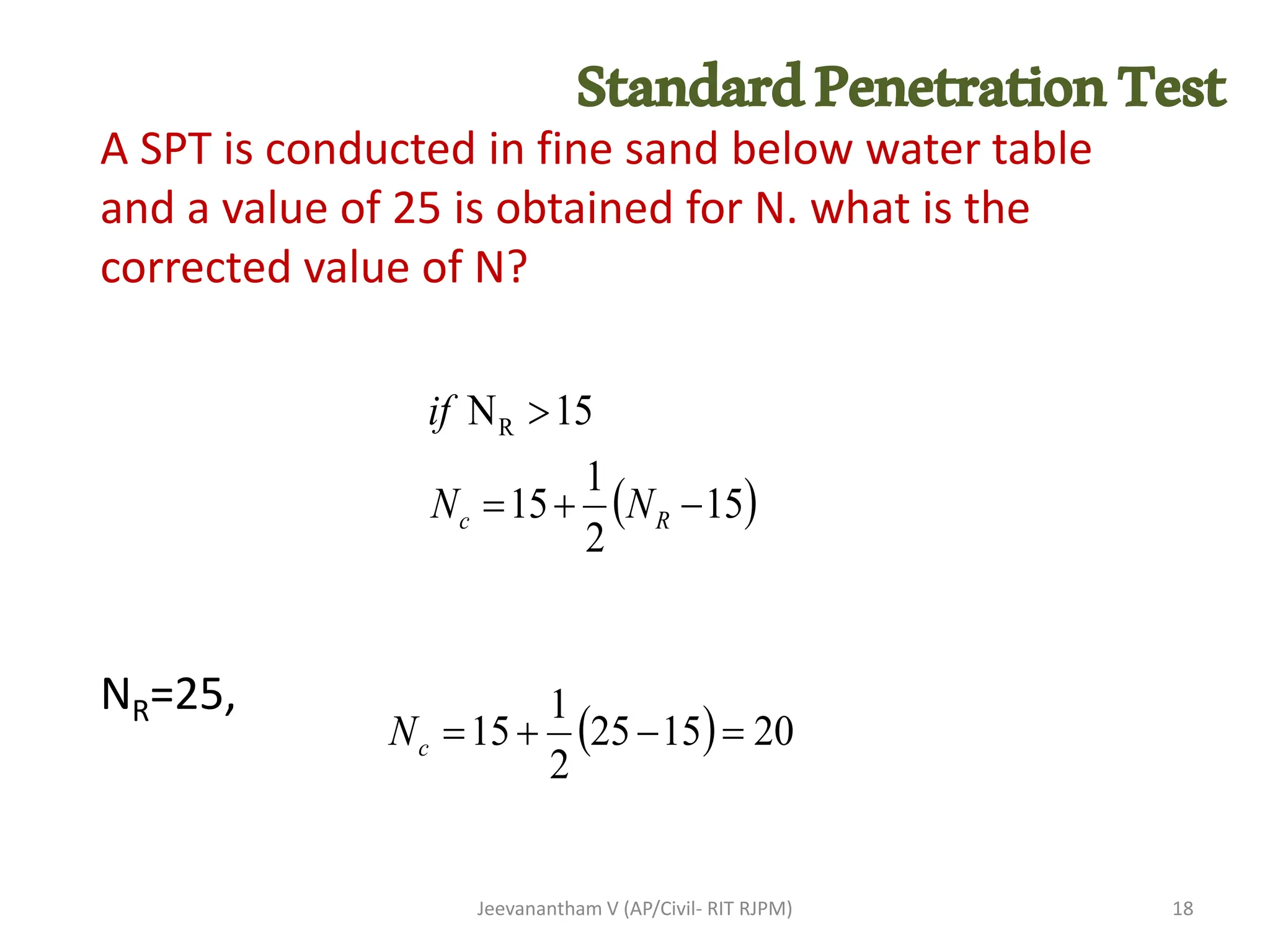
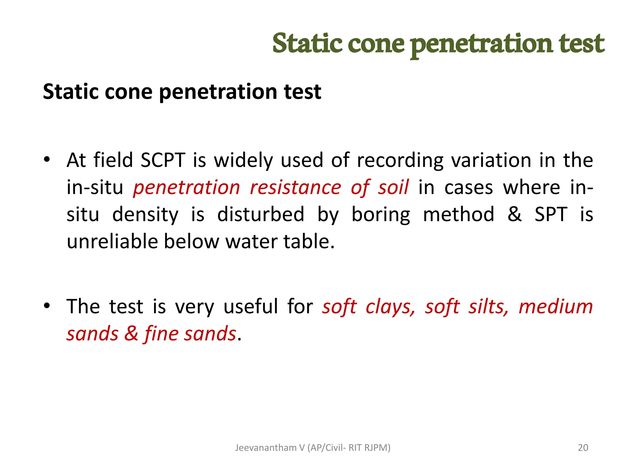
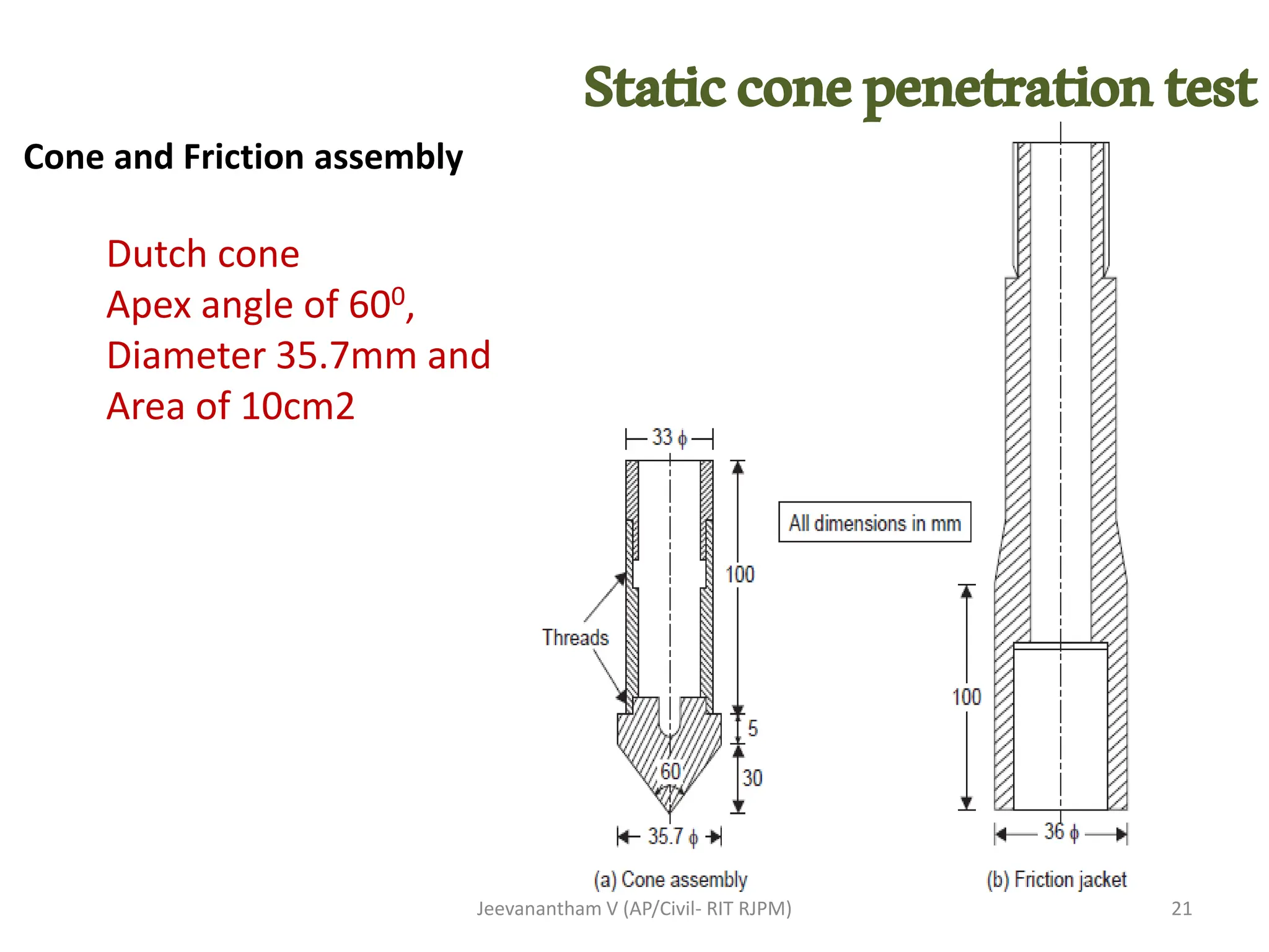
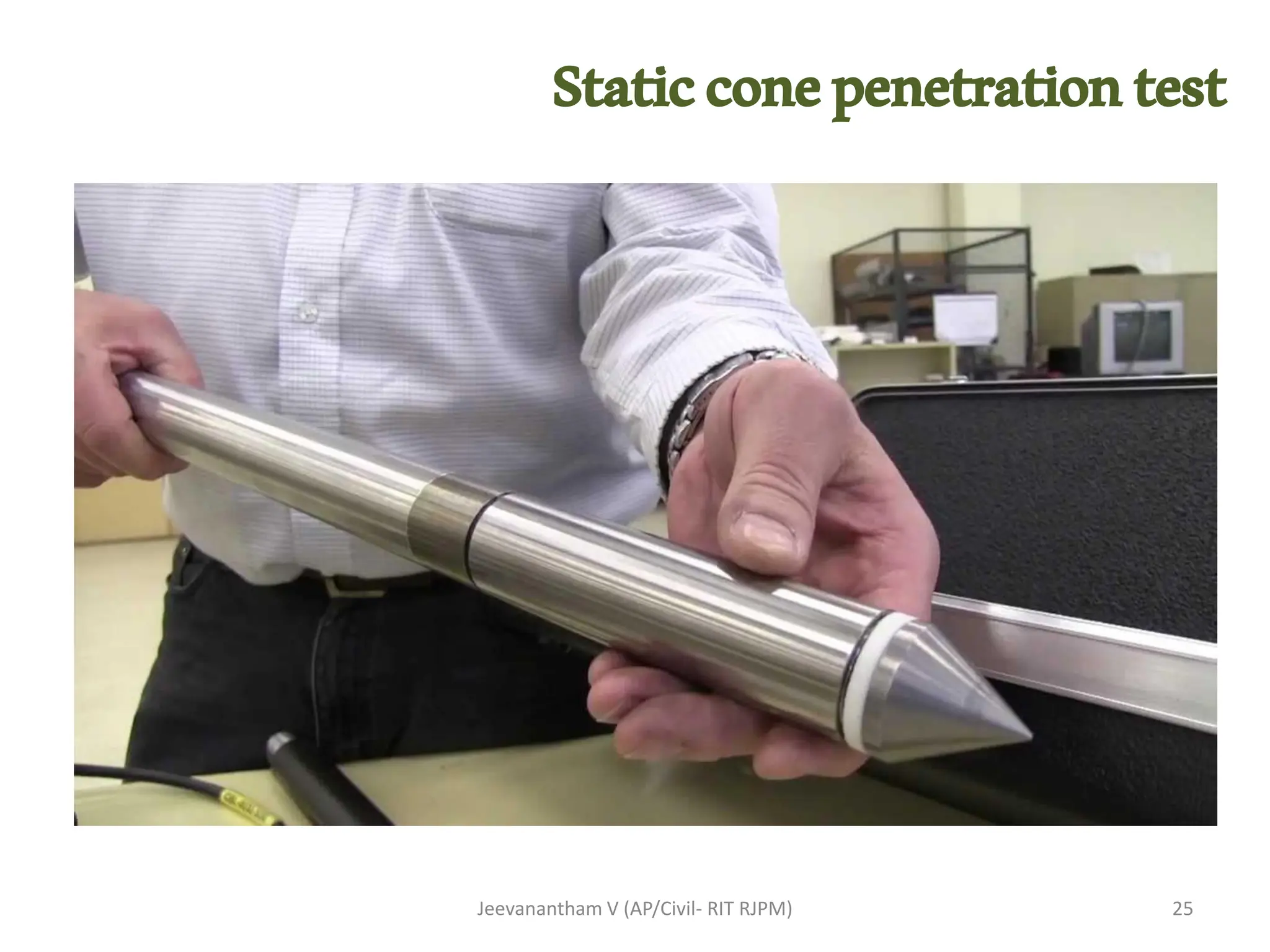
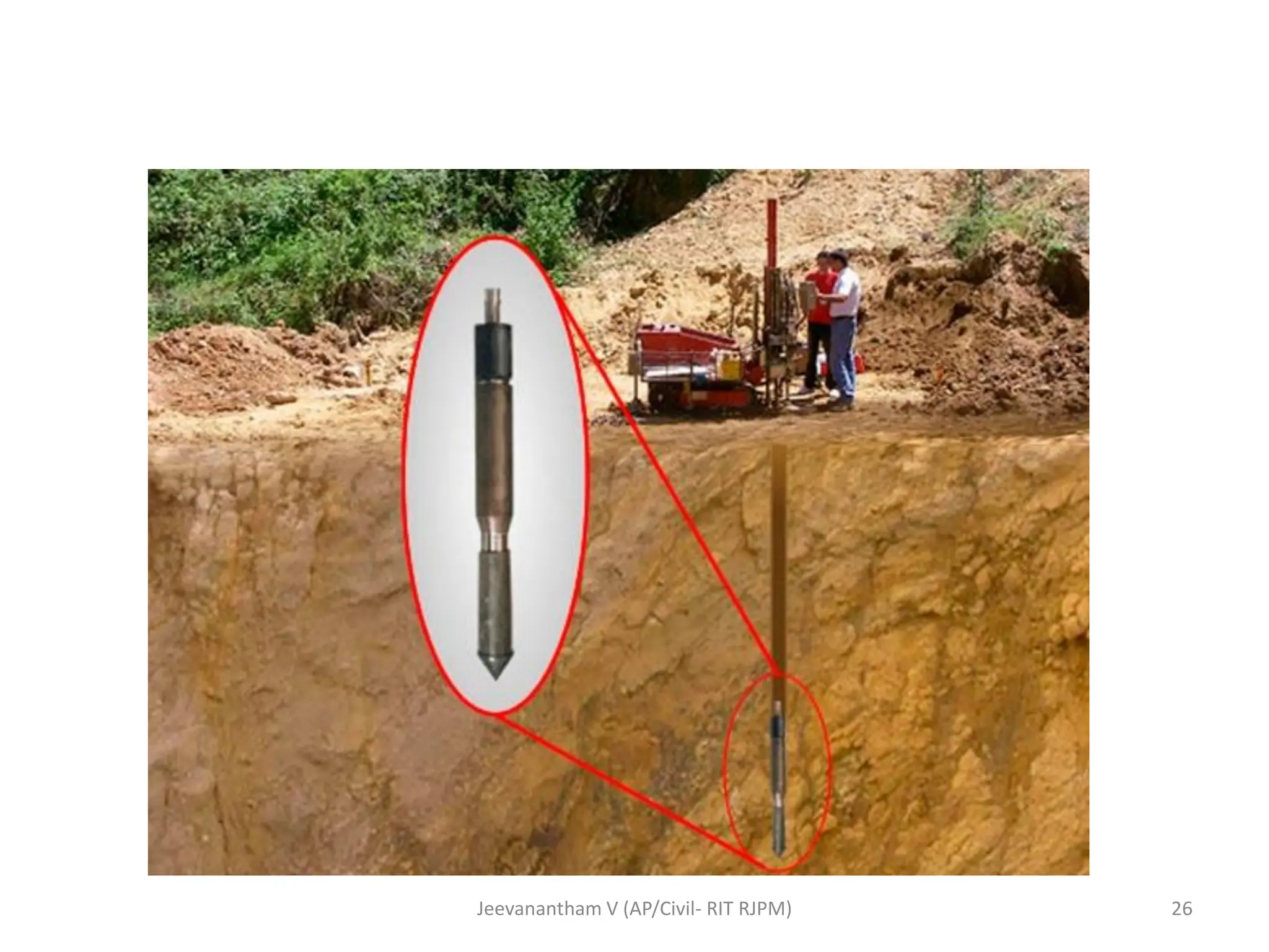
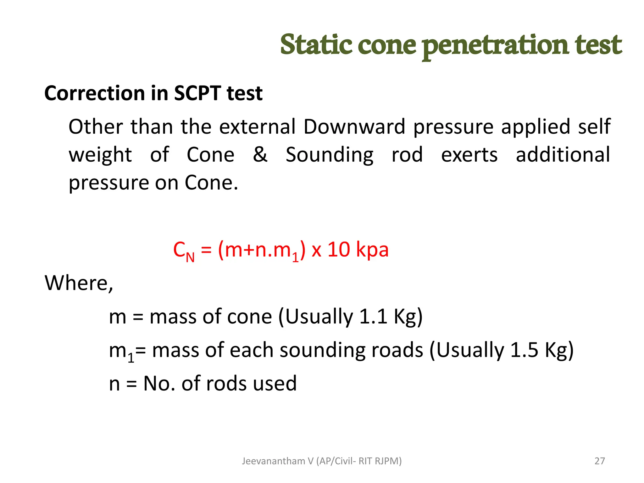
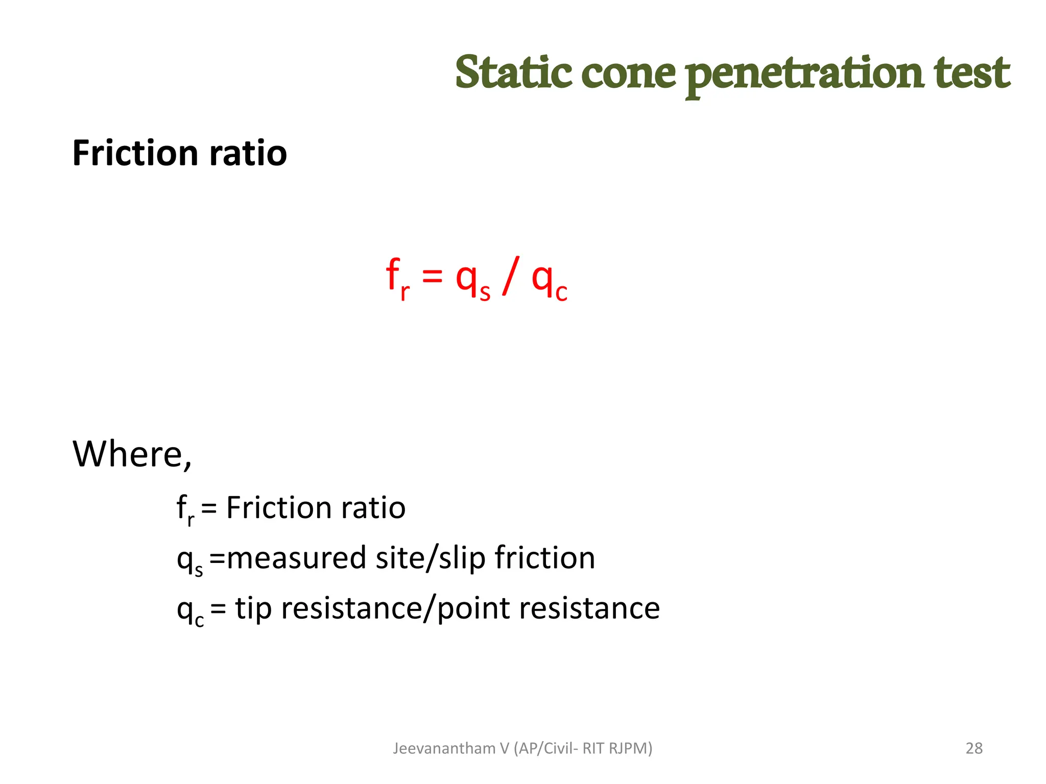
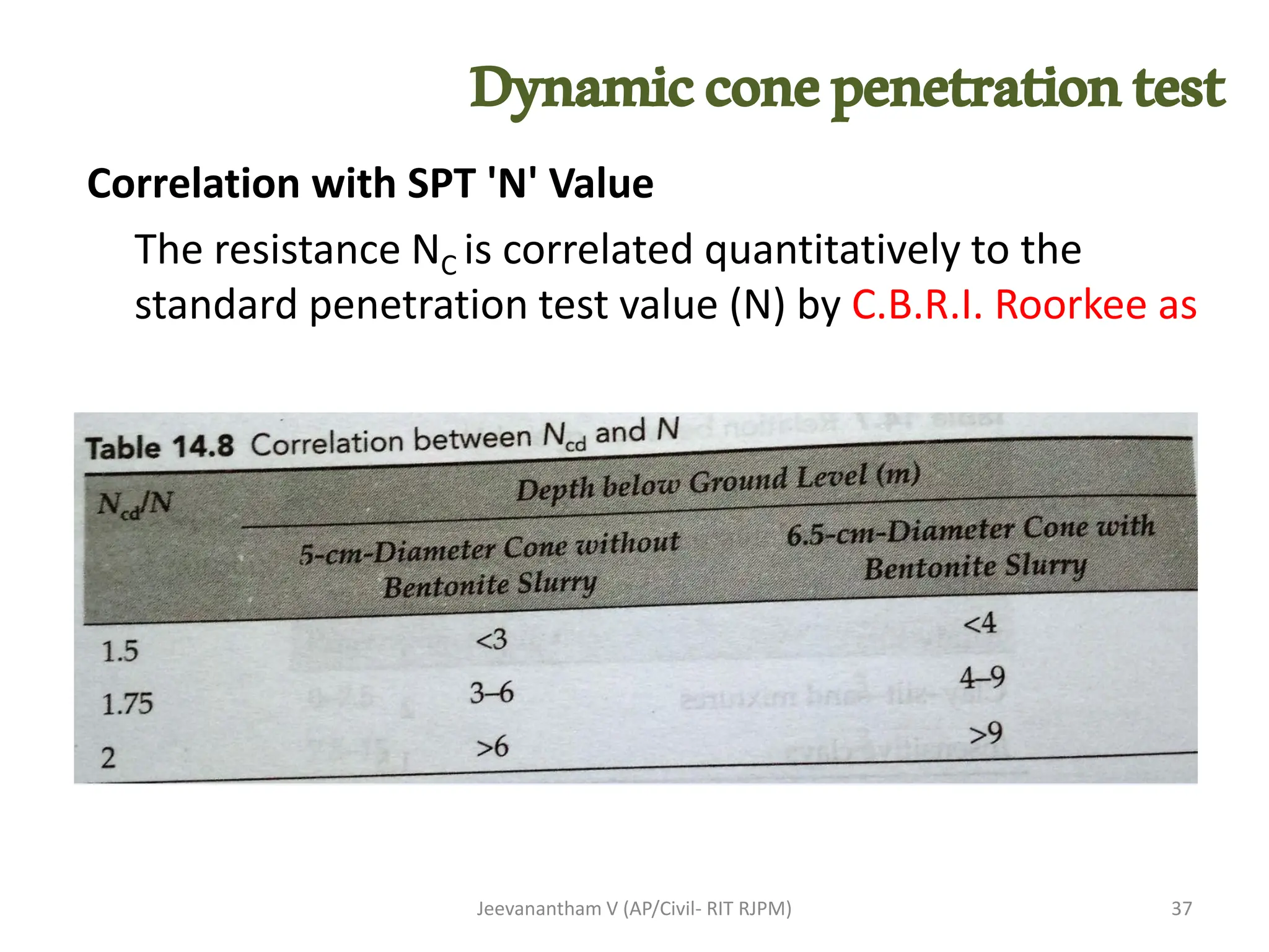
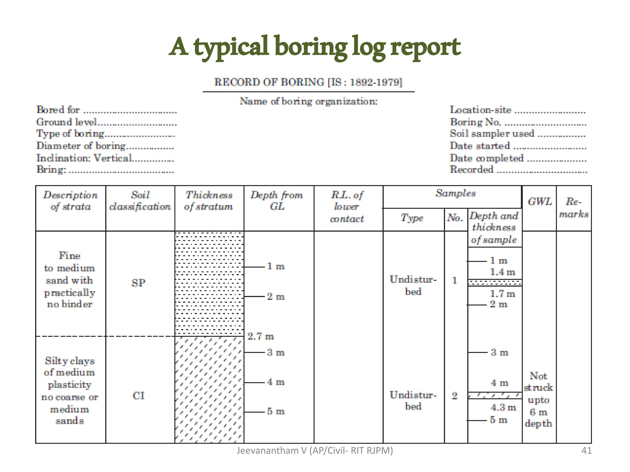
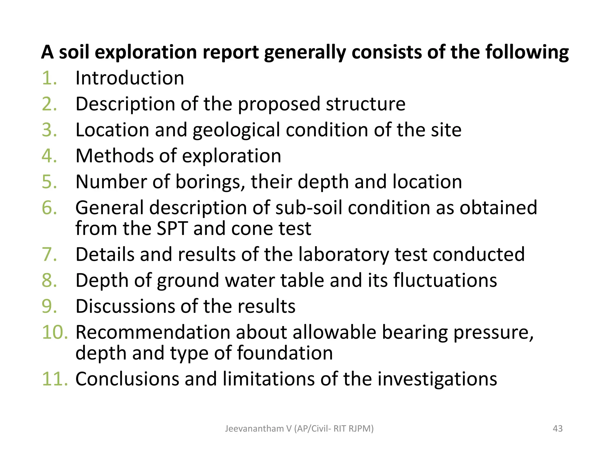
UNIT I
SITE INVESTIGATION AND SELECTION OF FOUNDATION
Scope and objectives – Methods of exploration –
Auguring and boring – Wash boring and rotary
drilling – Depth and spacing of bore holes – Soil
samples – Representative and undisturbed –
Sampling methods – Split spoon sampler, Thin wall
sampler, Stationary piston sampler – Penetration
tests (SPT and SCPT) – Data interpretation - Strength
parameters and Evaluation of Liquefaction potential -
Selection of foundation based on soil condition- Bore
log report.
1
Jeevanantham V (AP/Civil- RIT RJPM)
Penetrationtests
Penetration
tests
Standard
Penetration Test
Cone
Penetration Test
Jeevanantham V (AP/Civil- RIT RJPM) 2
StandardPenetrationTest
Jeevanantham V (AP/Civil- RIT RJPM)
❖ The standard penetration test is carried out in a borehole
❖ All the Penetration tests measure the resistance of the soil
strata to penetration.
❖ Useful empirical correlations are available between
penetration resistance and soil properties for use in
foundation design.
❖ This is the most extensively used penetrometer test and
employs a split-spoon sampler, which consists of a driving
shoe, a split-barrel of circular cross-section which is
longitudinally split into two parts and a coupling.
❖ IS: 2131-1981 gives the standard for carrying out the test.
3
StandardPenetrationTest
Objective :
❖Commonly used for cohesion less & cohesive soil
❖Used to determine relative density, angle of shearing
resistance and unconfined compressive strength
Procedure:
➢Bore hole is drilled to a certain depth, the drilling tools are
removed and the spilt spoon sampler is attached and lower
to the bottom of hole
➢Sampler is driven by drop hammer of 63.5kg falling from
height of 750mm.
➢The sampler is driven for every 150mm depth and number
of blows is recorded
➢The number of blows for the last two 150mm is noted as
Standard Penetration Number (N)
Jeevanantham V (AP/Civil- RIT RJPM) 4
• The SPT is carried out at every 0.75 m vertical intervals in a
borehole.
• This can be increased to 1.50 m if the depth of borehole is
large.
• Due to the presence of boulders or rocks, it may not be
possible to drive the sampler to a distance of 450 mm.
• In such a case, the N value can be recorded for the first 300
mm penetration.
• The test is stopped (Refusal) if,
1. 50 blows for any 150mm penetration or
2. Total 100 blows for 450mm penetration or
3. 10 successive blows produce no advance.
Jeevanantham V (AP/Civil- RIT RJPM) 5
StandardPenetrationTest
Jeevanantham V (AP/Civil- RIT RJPM) 6
StandardPenetrationTest
Jeevanantham V (AP/Civil- RIT RJPM) 7
Split Spoon Sampler
Precautions
➢The drill rods should be of Standard specification and
should not be in bent condition.
➢The split spoon sampler must be in good condition and the
cutting shoe must be free from wear and tear.
➢The drop hammer must be of the right weight and the fall
should be free, frictionless and vertical. The height of fall
must be exactly 750 mm.
➢Any change from this will seriously affect the N value. The
bottom of the borehole must be properly cleaned before
the test is carried out.
Jeevanantham V (AP/Civil- RIT RJPM) 8
StandardPenetrationTest
• When a casing is used in borehole, it should be ensured
that the casing is driven just short*** of the level at
which the SPT is to be carried out.
• When the test is carried out in a sandy soil below the
water table, it must be ensured that the water level in
the borehole is always maintained slightly above the
ground water level.
• If the water level in the borehole is lower than the
ground water level, ‘quick' condition may develop in the
soil and very low N values may be recorded.
Jeevanantham V (AP/Civil- RIT RJPM) 9
StandardPenetrationTest
Correction
• SPT values obtained in the field for sand have to be
corrected before they are used in empirical correlations
and design charts.
• IS: 2131-1981 recommends that the field value of N be
corrected for two effects, namely,
(a) effect of overburden pressure, and
(b) effect of dilatancy.
Jeevanantham V (AP/Civil- RIT RJPM) 10
StandardPenetrationTest
(a) Correction for overburden pressure
• N value in a granular soil is influenced by the overburden
pressure.
• Since the confining pressure (which is directly
proportional to the overburden pressure) increases with
depth, the N values at shallow depths are
underestimated and the N values at larger depths are
overestimated.
• To allow for this, N values recorded from field tests at
different effective overburden pressures are corrected to
a standard effective overburden pressure of 100kpa
Jeevanantham V (AP/Civil- RIT RJPM) 11
StandardPenetrationTest
Jeevanantham V (AP/Civil- RIT RJPM) 12
(b) Dilatancy correction
• Applied after overburden correction, exceeds 15 in
saturated fine sands and silts.
• IS: 2131-1981 incorporates the Terzaghi and Peck
recommended dilatancy correction (when > 15)
• >15 is an indication of a dense sand. In such a soil, the
fast rate of application of shear through the blows of a
drop hammer, is likely to induce negative pore water
pressure in a saturated fine sand.
• Consequently, a transient increase in shear resistance will
occur, leading to a SPT value higher than the actual one.
Jeevanantham V (AP/Civil- RIT RJPM) 13
StandardPenetrationTest
( )
15
2
1
15
15
NR
−
+
=

R
c N
N
if
14
Jeevanantham V (AP/Civil- RIT RJPM)
StandardPenetrationTest
Jeevanantham V (AP/Civil- RIT RJPM) 1
‘N’ Value Correlation to Engineering Properties
StandardPenetrationTest
Relation Between
angle of internal
friction & N value
16
Jeevanantham V (AP/Civil- RIT RJPM)
‘N’ Value Correlation to
Engineering Properties
StandardPenetrationTest
Jeevanantham V (AP/Civil- RIT RJPM) 17
‘N’ Value Correlation to Engineering Properties
StandardPenetrationTest
A SPT is conducted in fine sand below water table
and a value of 25 is obtained for N. what is the
corrected value of N?
NR=25,
Jeevanantham V (AP/Civil- RIT RJPM)
( )
15
2
1
15
15
NR
−
+
=

R
c N
N
if
( ) 20
15
25
2
1
15 =
−
+
=
c
N
18
StandardPenetrationTest
Staticconepenetrationtest
Jeevanantham V (AP/Civil- RIT RJPM) 19
Static cone penetration test
• At field SCPT is widely used of recording variation in the
in-situ penetration resistance of soil in cases where in-
situ density is disturbed by boring method & SPT is
unreliable below water table.
• The test is very useful for soft clays, soft silts, medium
sands & fine sands.
Jeevanantham V (AP/Civil- RIT RJPM) 20
Staticconepenetrationtest
Cone and Friction assembly
21
Jeevanantham V (AP/Civil- RIT RJPM)
Staticconepenetrationtest
Dutch cone
Apex angle of 600,
Diameter 35.7mm and
Area of 10cm2
Procedure
• After installing the equipment as per IS-4968, part III the
sounding rod is pushed into the soil and the driving
(Gradual push) is operated at the steady rate of 10 to 20
mm/sec approximately so as to advance the cone only by
external loading to the soil strata.
• After recording the cone resistance value, the sleeve is
pushed on to the cone and both are driven together into
the soil and combined resistance is noted.
• The resistance of sleeve is find out by subtracting cone
resistance from the combined resistance.
Jeevanantham V (AP/Civil- RIT RJPM) 22
Staticconepenetrationtest
Jeevanantham V (AP/Civil- RIT RJPM) 23
Typical Test Set up for SCPT
Staticconepenetrationtest
Jeevanantham V (AP/Civil- RIT RJPM) 1
Staticconepenetrationtest
Jeevanantham V (AP/Civil- RIT RJPM) 25
Staticconepenetrationtest
Jeevanantham V (AP/Civil- RIT RJPM) 26
Correction in SCPT test
Other than the external Downward pressure applied self
weight of Cone & Sounding rod exerts additional
pressure on Cone.
CN = (m+n.m1) x 10 kpa
Where,
m = mass of cone (Usually 1.1 Kg)
m1= mass of each sounding roads (Usually 1.5 Kg)
n = No. of rods used
Jeevanantham V (AP/Civil- RIT RJPM) 27
Staticconepenetrationtest
Friction ratio
fr = qs / qc
Where,
fr = Friction ratio
qs =measured site/slip friction
qc = tip resistance/point resistance
Jeevanantham V (AP/Civil- RIT RJPM) 28
Staticconepenetrationtest
Limitations
1. This test is unsuitable for gravelly soil & soil for having
SPT N value greater than 50.
2. Also in dense sand anchorage becomes to cumbersome
& expensive and for such cases Dynamic SPT can be
used.
3. This test is also unsuitable for field operation since
erroneous value obtained due to presence of brick bats,
loose stones etc.
Jeevanantham V (AP/Civil- RIT RJPM) 29
Staticconepenetrationtest
Type of Soil qc (kN/m2)
Gravel 800N to 1000N
Sands 500N to 600N
Silty sands 300N to 400N
Silts and clayey silts 200N
30
Jeevanantham V (AP/Civil- RIT RJPM)
Staticconepenetrationtest
‘N’ Value relationship to the qc value
Jeevanantham V (AP/Civil- RIT RJPM) 31
Dynamicconepenetrationtest(DCPT)
Jeevanantham V (AP/Civil- RIT RJPM) 32
Dynamicconepenetrationtest
Dynamic cone penetration test (DCPT)
• The aim is to determine the effort required to force a
point through the soil and so obtain resistance value
which corresponds to the mechanical properties of the
soil.
• The preliminary use is in cohesionless soils when static
penetration test is difficult to perform or dynamic
properties of the soil are of special interest.
Jeevanantham V (AP/Civil- RIT RJPM) 33
DynamicConePenetrationTest
Procedure:
• Test is performed by using a
➢50mm cone without bentonite slurry (or)
➢by using a 65 mm cone with bentonite slurry.
• For the circulation of the bentonite slurry the pumping unit of
the bentonite slurry is properly connected to the guide rod
through flexible tube.
• The standard 600 cone is connected to the drilling rod. The
driving head with the guide rod is connected and properly
fixed on the top of the drilled rods.
• This complete assembly is kept in position with the cone
resting vertically on the ground where the test is to be carried
out.
Jeevanantham V (AP/Civil- RIT RJPM) 34
Procedure:
• The cone is driven by a 65kg hammer falling through a
height of 75 cm.
• The number of blows for every 10cm penetration is
recorded
• The number of blows for 30cm penetration is taken as
dynamic cone resistance
• When a 65mm cone is used, sufficient circulation of the
bentonite slurry is necessary for elimination of the
friction on the rods.
• Sometimes the bentonite slurry is not used when the
investigation is required up to a depth of 6m only.
Jeevanantham V (AP/Civil- RIT RJPM) 35
Dynamicconepenetrationtest
Jeevanantham V (AP/Civil- RIT RJPM) 36
Dynamicconepenetrationtest
Correlation with SPT 'N' Value
The resistance NC is correlated quantitatively to the
standard penetration test value (N) by C.B.R.I. Roorkee as
Jeevanantham V (AP/Civil- RIT RJPM) 37
Dynamicconepenetrationtest
Advantages :
• The test does not need a borehole.
• It can be done quickly to cover a large area economically.
• The test helps to identify variability of subsoil profile and
to locate soft pockets such as filled up ponds.
• When DCPT is carried out close to a few boreholes,
suitable corrections may be obtained for a particular site
• and the number of bore holes can be reduced.
Jeevanantham V (AP/Civil- RIT RJPM) 38
Dynamicconepenetrationtest
Disadvantages :
• The test is normally not suitable for cohesive soils or very
loose cohesionless soils.
• It is normally not possible to evaluate the mechanical
properties of the soil at great depths when the friction
• along the extension rod is significant.
Jeevanantham V (AP/Civil- RIT RJPM) 39
Dynamicconepenetrationtest
BoreLog
Jeevanantham V (AP/Civil- RIT RJPM) 40
Atypicalboringlogreport
41
Jeevanantham V (AP/Civil- RIT RJPM)
Jeevanantham V (AP/Civil- RIT RJPM) 42
A soil exploration report generally consists of the following
1. Introduction
2. Description of the proposed structure
3. Location and geological condition of the site
4. Methods of exploration
5. Number of borings, their depth and location
6. General description of sub-soil condition as obtained
from the SPT and cone test
7. Details and results of the laboratory test conducted
8. Depth of ground water table and its fluctuations
9. Discussions of the results
10. Recommendation about allowable bearing pressure,
depth and type of foundation
11. Conclusions and limitations of the investigations
43
Jeevanantham V (AP/Civil- RIT RJPM)
Thankyou
44
Jeevanantham V (AP/Civil- RIT RJPM)

Soil Penetration Tests to assess the strength parameters of soil

  • 1.
    UNIT I SITE INVESTIGATIONAND SELECTION OF FOUNDATION Scope and objectives – Methods of exploration – Auguring and boring – Wash boring and rotary drilling – Depth and spacing of bore holes – Soil samples – Representative and undisturbed – Sampling methods – Split spoon sampler, Thin wall sampler, Stationary piston sampler – Penetration tests (SPT and SCPT) – Data interpretation - Strength parameters and Evaluation of Liquefaction potential - Selection of foundation based on soil condition- Bore log report. 1 Jeevanantham V (AP/Civil- RIT RJPM)
  • 2.
  • 3.
    StandardPenetrationTest Jeevanantham V (AP/Civil-RIT RJPM) ❖ The standard penetration test is carried out in a borehole ❖ All the Penetration tests measure the resistance of the soil strata to penetration. ❖ Useful empirical correlations are available between penetration resistance and soil properties for use in foundation design. ❖ This is the most extensively used penetrometer test and employs a split-spoon sampler, which consists of a driving shoe, a split-barrel of circular cross-section which is longitudinally split into two parts and a coupling. ❖ IS: 2131-1981 gives the standard for carrying out the test. 3
  • 4.
    StandardPenetrationTest Objective : ❖Commonly usedfor cohesion less & cohesive soil ❖Used to determine relative density, angle of shearing resistance and unconfined compressive strength Procedure: ➢Bore hole is drilled to a certain depth, the drilling tools are removed and the spilt spoon sampler is attached and lower to the bottom of hole ➢Sampler is driven by drop hammer of 63.5kg falling from height of 750mm. ➢The sampler is driven for every 150mm depth and number of blows is recorded ➢The number of blows for the last two 150mm is noted as Standard Penetration Number (N) Jeevanantham V (AP/Civil- RIT RJPM) 4
  • 5.
    • The SPTis carried out at every 0.75 m vertical intervals in a borehole. • This can be increased to 1.50 m if the depth of borehole is large. • Due to the presence of boulders or rocks, it may not be possible to drive the sampler to a distance of 450 mm. • In such a case, the N value can be recorded for the first 300 mm penetration. • The test is stopped (Refusal) if, 1. 50 blows for any 150mm penetration or 2. Total 100 blows for 450mm penetration or 3. 10 successive blows produce no advance. Jeevanantham V (AP/Civil- RIT RJPM) 5 StandardPenetrationTest
  • 6.
    Jeevanantham V (AP/Civil-RIT RJPM) 6 StandardPenetrationTest
  • 7.
  • 8.
    Precautions ➢The drill rodsshould be of Standard specification and should not be in bent condition. ➢The split spoon sampler must be in good condition and the cutting shoe must be free from wear and tear. ➢The drop hammer must be of the right weight and the fall should be free, frictionless and vertical. The height of fall must be exactly 750 mm. ➢Any change from this will seriously affect the N value. The bottom of the borehole must be properly cleaned before the test is carried out. Jeevanantham V (AP/Civil- RIT RJPM) 8 StandardPenetrationTest
  • 9.
    • When acasing is used in borehole, it should be ensured that the casing is driven just short*** of the level at which the SPT is to be carried out. • When the test is carried out in a sandy soil below the water table, it must be ensured that the water level in the borehole is always maintained slightly above the ground water level. • If the water level in the borehole is lower than the ground water level, ‘quick' condition may develop in the soil and very low N values may be recorded. Jeevanantham V (AP/Civil- RIT RJPM) 9 StandardPenetrationTest
  • 10.
    Correction • SPT valuesobtained in the field for sand have to be corrected before they are used in empirical correlations and design charts. • IS: 2131-1981 recommends that the field value of N be corrected for two effects, namely, (a) effect of overburden pressure, and (b) effect of dilatancy. Jeevanantham V (AP/Civil- RIT RJPM) 10 StandardPenetrationTest
  • 11.
    (a) Correction foroverburden pressure • N value in a granular soil is influenced by the overburden pressure. • Since the confining pressure (which is directly proportional to the overburden pressure) increases with depth, the N values at shallow depths are underestimated and the N values at larger depths are overestimated. • To allow for this, N values recorded from field tests at different effective overburden pressures are corrected to a standard effective overburden pressure of 100kpa Jeevanantham V (AP/Civil- RIT RJPM) 11 StandardPenetrationTest
  • 12.
  • 13.
    (b) Dilatancy correction •Applied after overburden correction, exceeds 15 in saturated fine sands and silts. • IS: 2131-1981 incorporates the Terzaghi and Peck recommended dilatancy correction (when > 15) • >15 is an indication of a dense sand. In such a soil, the fast rate of application of shear through the blows of a drop hammer, is likely to induce negative pore water pressure in a saturated fine sand. • Consequently, a transient increase in shear resistance will occur, leading to a SPT value higher than the actual one. Jeevanantham V (AP/Civil- RIT RJPM) 13 StandardPenetrationTest
  • 14.
    ( ) 15 2 1 15 15 NR − + =  R c N N if 14 JeevananthamV (AP/Civil- RIT RJPM) StandardPenetrationTest
  • 15.
    Jeevanantham V (AP/Civil-RIT RJPM) 1 ‘N’ Value Correlation to Engineering Properties StandardPenetrationTest
  • 16.
    Relation Between angle ofinternal friction & N value 16 Jeevanantham V (AP/Civil- RIT RJPM) ‘N’ Value Correlation to Engineering Properties StandardPenetrationTest
  • 17.
    Jeevanantham V (AP/Civil-RIT RJPM) 17 ‘N’ Value Correlation to Engineering Properties StandardPenetrationTest
  • 18.
    A SPT isconducted in fine sand below water table and a value of 25 is obtained for N. what is the corrected value of N? NR=25, Jeevanantham V (AP/Civil- RIT RJPM) ( ) 15 2 1 15 15 NR − + =  R c N N if ( ) 20 15 25 2 1 15 = − + = c N 18 StandardPenetrationTest
  • 19.
  • 20.
    Static cone penetrationtest • At field SCPT is widely used of recording variation in the in-situ penetration resistance of soil in cases where in- situ density is disturbed by boring method & SPT is unreliable below water table. • The test is very useful for soft clays, soft silts, medium sands & fine sands. Jeevanantham V (AP/Civil- RIT RJPM) 20 Staticconepenetrationtest
  • 21.
    Cone and Frictionassembly 21 Jeevanantham V (AP/Civil- RIT RJPM) Staticconepenetrationtest Dutch cone Apex angle of 600, Diameter 35.7mm and Area of 10cm2
  • 22.
    Procedure • After installingthe equipment as per IS-4968, part III the sounding rod is pushed into the soil and the driving (Gradual push) is operated at the steady rate of 10 to 20 mm/sec approximately so as to advance the cone only by external loading to the soil strata. • After recording the cone resistance value, the sleeve is pushed on to the cone and both are driven together into the soil and combined resistance is noted. • The resistance of sleeve is find out by subtracting cone resistance from the combined resistance. Jeevanantham V (AP/Civil- RIT RJPM) 22 Staticconepenetrationtest
  • 23.
    Jeevanantham V (AP/Civil-RIT RJPM) 23 Typical Test Set up for SCPT Staticconepenetrationtest
  • 24.
    Jeevanantham V (AP/Civil-RIT RJPM) 1 Staticconepenetrationtest
  • 25.
    Jeevanantham V (AP/Civil-RIT RJPM) 25 Staticconepenetrationtest
  • 26.
  • 27.
    Correction in SCPTtest Other than the external Downward pressure applied self weight of Cone & Sounding rod exerts additional pressure on Cone. CN = (m+n.m1) x 10 kpa Where, m = mass of cone (Usually 1.1 Kg) m1= mass of each sounding roads (Usually 1.5 Kg) n = No. of rods used Jeevanantham V (AP/Civil- RIT RJPM) 27 Staticconepenetrationtest
  • 28.
    Friction ratio fr =qs / qc Where, fr = Friction ratio qs =measured site/slip friction qc = tip resistance/point resistance Jeevanantham V (AP/Civil- RIT RJPM) 28 Staticconepenetrationtest
  • 29.
    Limitations 1. This testis unsuitable for gravelly soil & soil for having SPT N value greater than 50. 2. Also in dense sand anchorage becomes to cumbersome & expensive and for such cases Dynamic SPT can be used. 3. This test is also unsuitable for field operation since erroneous value obtained due to presence of brick bats, loose stones etc. Jeevanantham V (AP/Civil- RIT RJPM) 29 Staticconepenetrationtest
  • 30.
    Type of Soilqc (kN/m2) Gravel 800N to 1000N Sands 500N to 600N Silty sands 300N to 400N Silts and clayey silts 200N 30 Jeevanantham V (AP/Civil- RIT RJPM) Staticconepenetrationtest ‘N’ Value relationship to the qc value
  • 31.
  • 32.
  • 33.
    Dynamicconepenetrationtest Dynamic cone penetrationtest (DCPT) • The aim is to determine the effort required to force a point through the soil and so obtain resistance value which corresponds to the mechanical properties of the soil. • The preliminary use is in cohesionless soils when static penetration test is difficult to perform or dynamic properties of the soil are of special interest. Jeevanantham V (AP/Civil- RIT RJPM) 33
  • 34.
    DynamicConePenetrationTest Procedure: • Test isperformed by using a ➢50mm cone without bentonite slurry (or) ➢by using a 65 mm cone with bentonite slurry. • For the circulation of the bentonite slurry the pumping unit of the bentonite slurry is properly connected to the guide rod through flexible tube. • The standard 600 cone is connected to the drilling rod. The driving head with the guide rod is connected and properly fixed on the top of the drilled rods. • This complete assembly is kept in position with the cone resting vertically on the ground where the test is to be carried out. Jeevanantham V (AP/Civil- RIT RJPM) 34
  • 35.
    Procedure: • The coneis driven by a 65kg hammer falling through a height of 75 cm. • The number of blows for every 10cm penetration is recorded • The number of blows for 30cm penetration is taken as dynamic cone resistance • When a 65mm cone is used, sufficient circulation of the bentonite slurry is necessary for elimination of the friction on the rods. • Sometimes the bentonite slurry is not used when the investigation is required up to a depth of 6m only. Jeevanantham V (AP/Civil- RIT RJPM) 35 Dynamicconepenetrationtest
  • 36.
    Jeevanantham V (AP/Civil-RIT RJPM) 36 Dynamicconepenetrationtest
  • 37.
    Correlation with SPT'N' Value The resistance NC is correlated quantitatively to the standard penetration test value (N) by C.B.R.I. Roorkee as Jeevanantham V (AP/Civil- RIT RJPM) 37 Dynamicconepenetrationtest
  • 38.
    Advantages : • Thetest does not need a borehole. • It can be done quickly to cover a large area economically. • The test helps to identify variability of subsoil profile and to locate soft pockets such as filled up ponds. • When DCPT is carried out close to a few boreholes, suitable corrections may be obtained for a particular site • and the number of bore holes can be reduced. Jeevanantham V (AP/Civil- RIT RJPM) 38 Dynamicconepenetrationtest
  • 39.
    Disadvantages : • Thetest is normally not suitable for cohesive soils or very loose cohesionless soils. • It is normally not possible to evaluate the mechanical properties of the soil at great depths when the friction • along the extension rod is significant. Jeevanantham V (AP/Civil- RIT RJPM) 39 Dynamicconepenetrationtest
  • 40.
  • 41.
  • 42.
  • 43.
    A soil explorationreport generally consists of the following 1. Introduction 2. Description of the proposed structure 3. Location and geological condition of the site 4. Methods of exploration 5. Number of borings, their depth and location 6. General description of sub-soil condition as obtained from the SPT and cone test 7. Details and results of the laboratory test conducted 8. Depth of ground water table and its fluctuations 9. Discussions of the results 10. Recommendation about allowable bearing pressure, depth and type of foundation 11. Conclusions and limitations of the investigations 43 Jeevanantham V (AP/Civil- RIT RJPM)
  • 44.