Downloaded 946 times

![JPN Pahang Physics Module Form 4
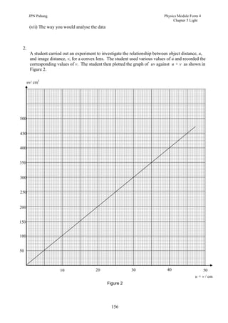
Chapter 5 Light
a) Based on the graph in Figure 2,
(i) state the relationship between uv and u + v
…………………………………………………………………………………………
[1 mark]
(ii) determine the value of u + v when the value of uv = 400 cm2. Show on the graph how
you obtained the value of u + v.
From the value of u + v obtained, calculate the image distance, v when u = 20 cm.
[3 marks]
(iii) calculate the gradient of the graph. Show clearly on the graph how you obtained the
values needed for the calculation.
[3 marks]
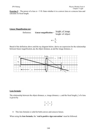
b) Given that the relationship between u, v and focal length, f of the convex lens used, is
represented by the equation
1 + 1 = 1
u v f
Derive an equation which gives the relationship between uv and (u + v ).
[2 marks]
c) Using the equation derived in (b), and the value of gradient calculated in (a)(iii), determine the
focal length of the lens used in the experiment.
[2 marks]
d) State one precaution taken to ensure the accuracy of the experiment.
…………………………………………………………………………………… [1 mark]
157](https://image.slidesharecdn.com/05-lightstudent-110310051652-phpapp01/85/SPM-PHYSICS-FORM-4-light-38-320.jpg)

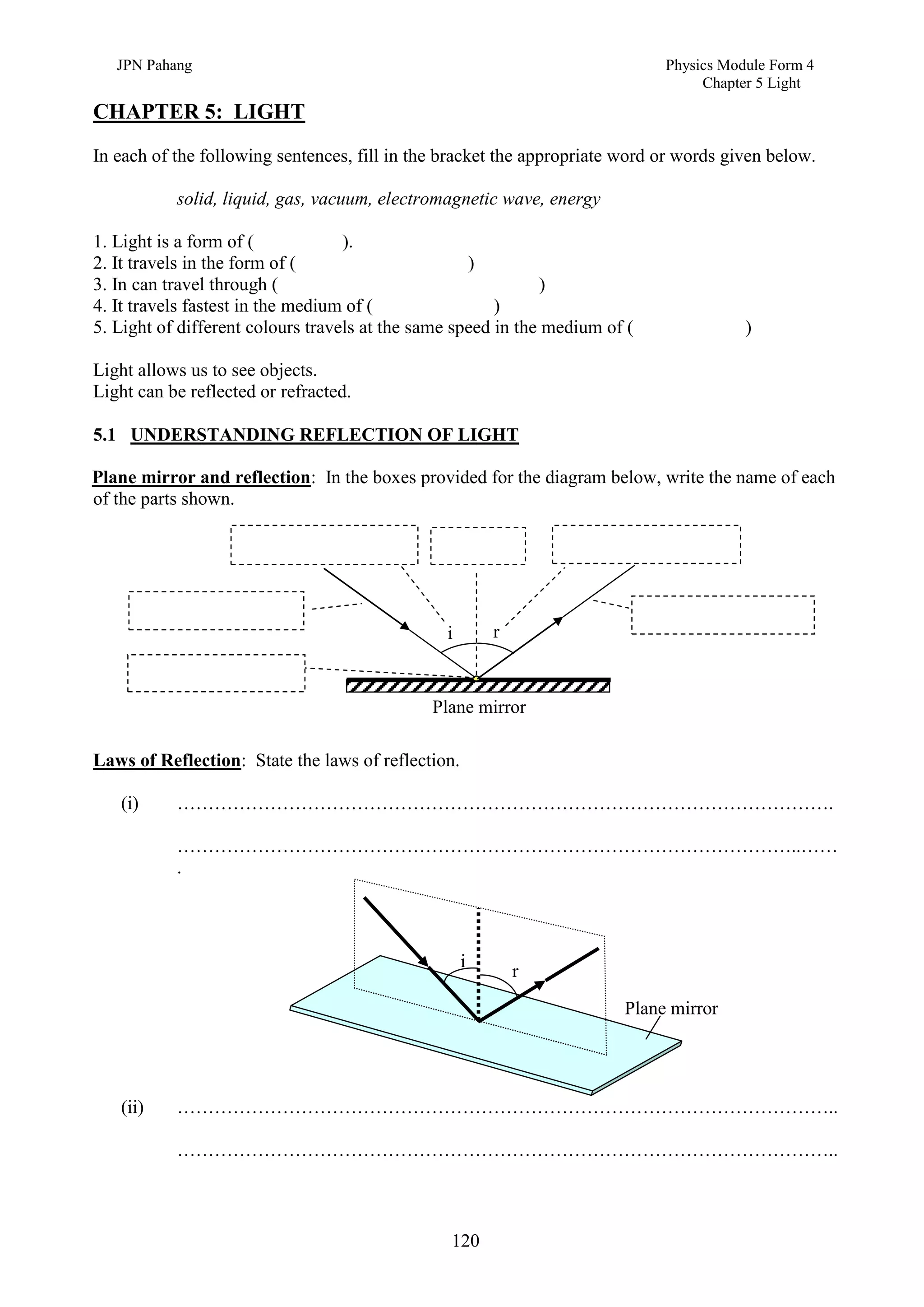
1. This document discusses light and its properties, including reflection from plane and curved mirrors. 2. Light travels as an electromagnetic wave and can travel through solids, liquids, gases, and vacuum, traveling fastest in vacuum. 3. Plane mirrors obey the laws of reflection - the angle of incidence equals the angle of reflection, and the incident ray, normal, and reflected ray all lie in the same plane. Images formed by plane mirrors are virtual, same-size, and laterally inverted.