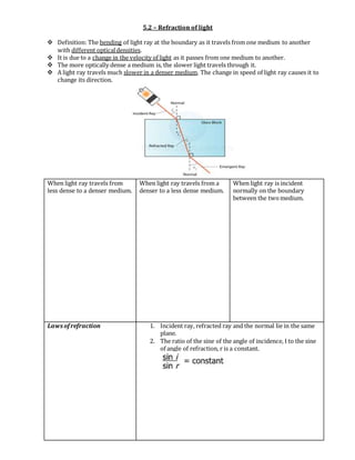
The document discusses the reflection and refraction of light. It defines reflection as light rays bouncing off a surface, while refraction is the bending of light rays when passing from one medium to another of different density. The key laws and concepts covered include:
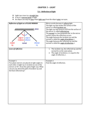
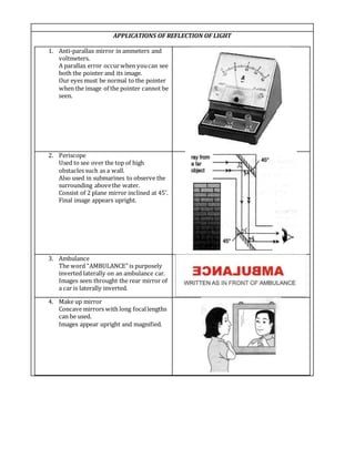
- The law of reflection, where the angle of incidence equals the angle of reflection
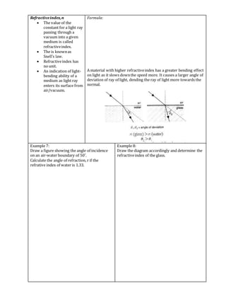
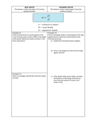
- Refractive index, which indicates how much a medium bends light
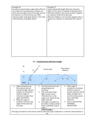
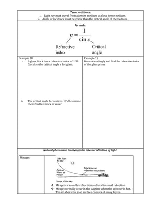
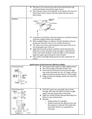
- Total internal reflection, which occurs when light travels from a dense to less dense medium at an angle greater than the critical angle
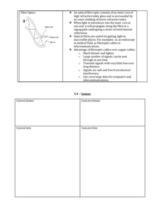
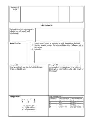
Several examples and applications are provided, such as plane mirrors, mirages, fiber optics, and lenses. Convex lenses form real images while concave lenses form virtual, upright,