Download to read offline

![Mahesh Kumar K M. Int. Journal of Engineering Research and Application www.ijera.com
ISSN : 2248-9622, Vol. 7, Issue 1, ( Part -4) January 2017, pp.34-39
www.ijera.com 35 | P a g e
[1] Microcontroller based speed control of three
phase induction motor using v/f method:
Induction motors are widely used AC motors in
industrial area. Advanced semiconductor technology
& use of microcontroller have made the speed
control of induction motor easier. The work makes
use of DSPIC30F2010 microcontroller, in order to
operate induction motor using V/F method. The
various factors which make the microcontroller
based system attractive are, 1. Improved reliability
and increased flexibility. 2. Simplicity of
implementation in variable speed drives 3. Low cost
and high accuracy 4. Possible to change torque
speed characteristics of drive by software
modification. The simplicity of this project is that it
can be operate by any person who need not know
microcontroller programming.
[2] V/F Speed Control of 3 phase Induction
Motor using Space Vector Modulation: The speed
control of three phase induction motor is essential
because the motor control industry is a dominant
sector. To remain competitive, new products must be
developed having several design aspects such as,
cost reduction, low power consumption & improved
power factor. A number of Pulse width modulations
(PWM) scheme is used to obtain variable voltage
and frequency supply from an inverter, such as Sine
wave Pulse Width Modulation (SPWM), Third
Harmonic Pulse Width Modulation (THPWM) and
Space Vector Pulse Width Modulation(SVPWM).
There is an increasing trend of using space
vector PWM (SVPWM) because of their easier
digital realization, better dc bus utilization and
output voltage is more closed to sinusoidal wave.
This paper aims at study of v/f speed control
technique for Induction Motor using Space Vector
Pulse Width Modulation technique with stepwise
understanding of v/f speed control method for three
phase induction motor and space vector modulation
and its realization by using MATLAB/SIMULINK
model for two level inverter.
[3] Speed Control of a Three Phase Induction
Motor Using PWM Inverter:
There are different methods of speed
control of three phase induction motor and to
control the speed of three phase induction motor
generally using V/F control strategy. Out of the a
number of methods of speed control of an
induction such as pole changing, frequency
variation, variable rotor resistance, variable
stator voltage, constant V/f control, slip recovery
method etc., the constant V/f speed control
method is the majority generally used. In this
method, the V/f ratio is kept constant which in
turn maintains the magnetizing flux constant so
that the maximum torque remains unchanged.
The simulation work proves the idea of V/F
control using PWM inverter and the software
used for simulation is PSIM (Powersim).The
performance of the volt per hertz strategy were
evaluated through simulation shown in results.
In constant V/F control, by use PWM inverter,
we can vary the supply voltage as well as the
supply frequency such that the V/F ratio remains
constant so that the flux remains constant too.
So, we can get different operating zone for
various speeds and torques and also we can get
different synchronous speed with almost same
maximum torque. Thus the motor is fully
utilized and also we have a good variety of speed
control. It is effortless, cost-effective to easier to
design in open loop. But the drawbacks of open
loop is it doesn’t correct the change in output
also it doesn’t reach the steady state quickly.
III. PROPOSED WORK
Many projects have been done in order to
improve the performance of three phase induction
motors by controlling the speed of induction motor
by various methods like sensor -based control of
three phase induction motor, speed control of
induction motor using PWM inverter technique,
speed control of induction motor using space vector
model etc.
Due to multi- variable, highly non- linear,
unavailability of measurements, complexity
involving the mathematical modelling, is still a
difficult and complex engineering problem. PLC
method of control had replaced traditional control
method which improves greatly dynamic control
efficiency of motor. The Programmable logic
controller can simultaneously evaluate data at a
faster rate thus increasing the efficiency of the motor
and resulting in its better performance.
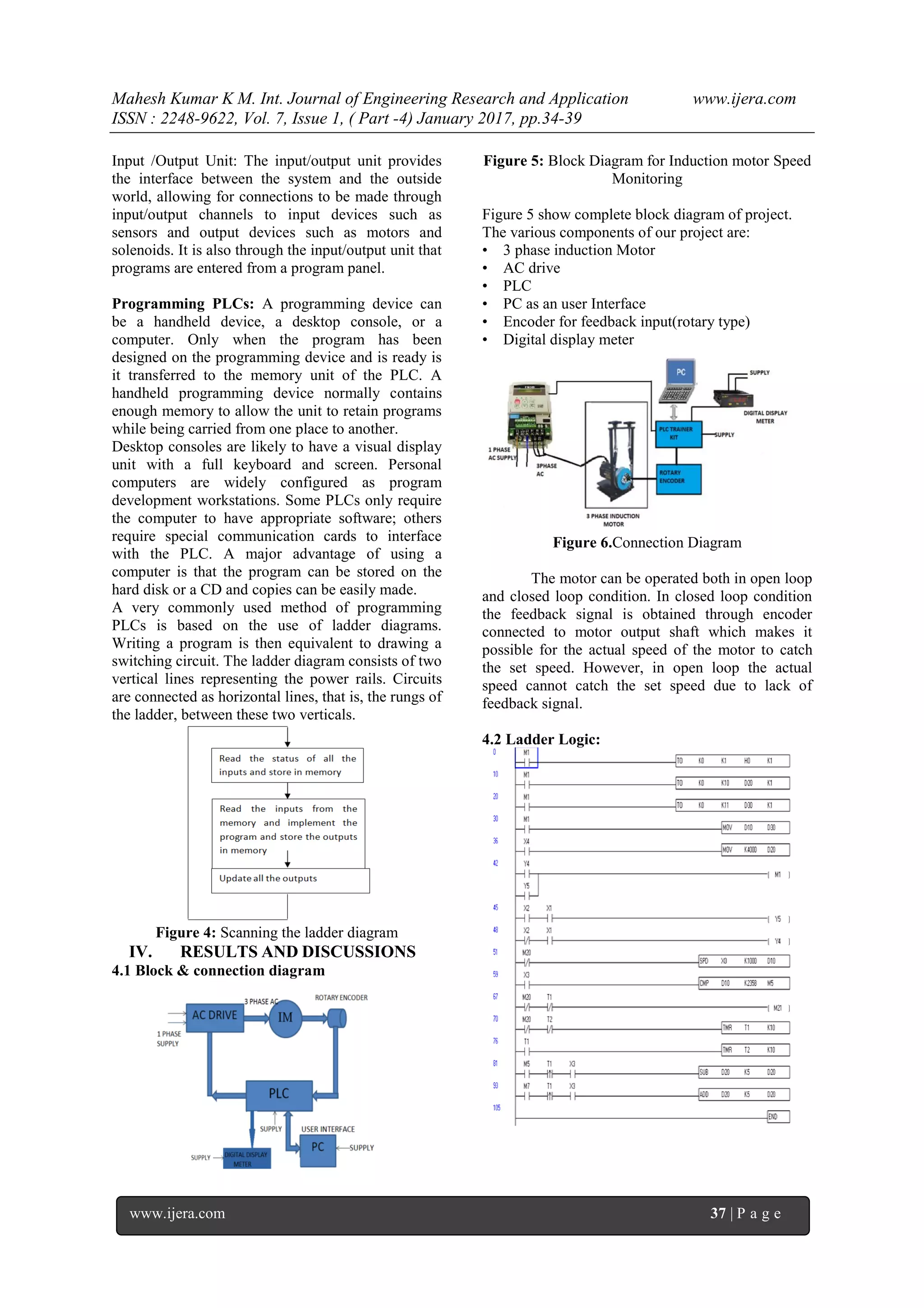
The objective of our work is to monitor
the speed of a three phase induction motor under
various operating conditions such as no load and
on load. The motor control is attempted with a
Programmable logic controller, to realize in open
loop and closed loop operation under various
operating conditions.
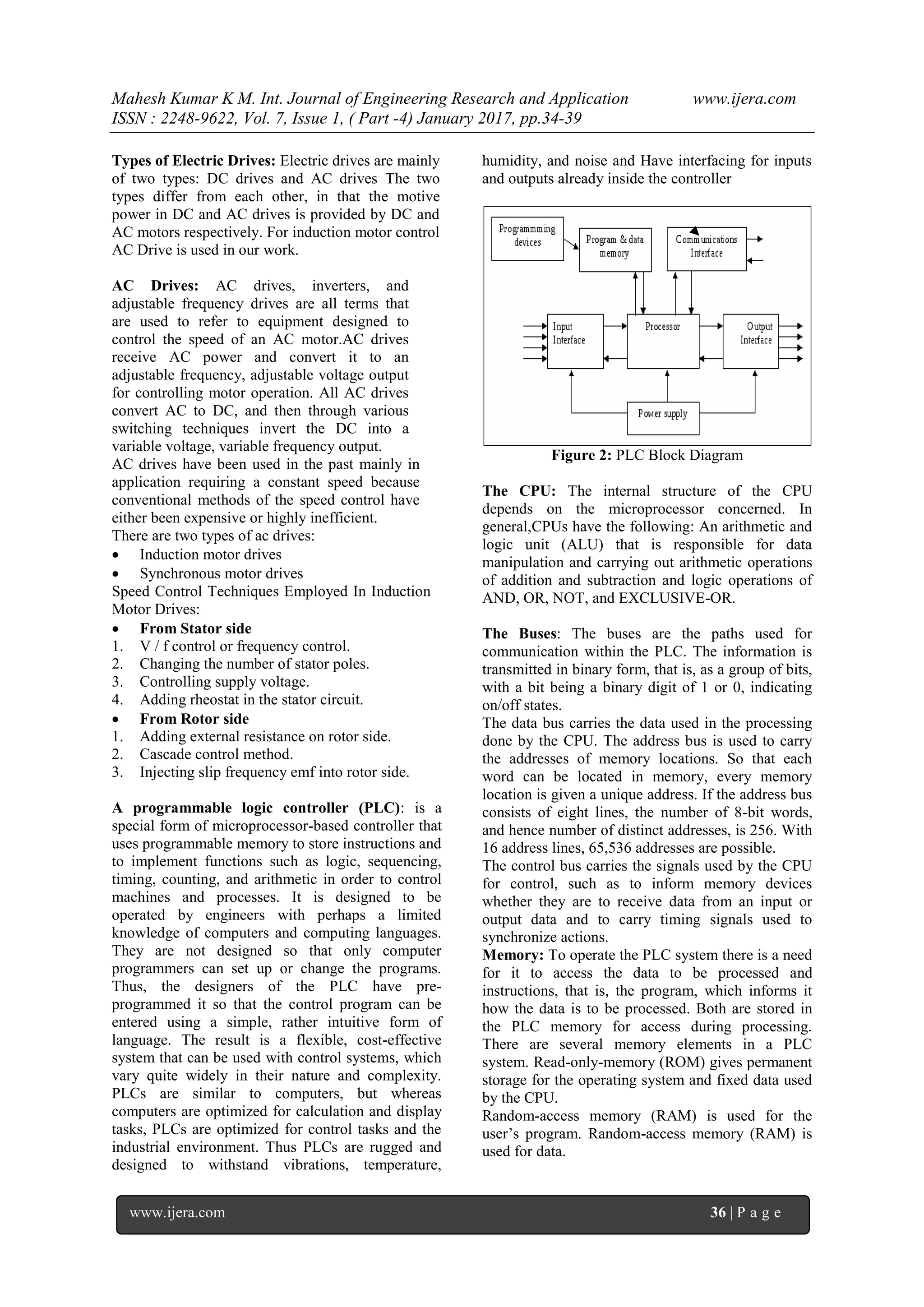
Figure shows Block Diagram of Electric Drive](https://image.slidesharecdn.com/h0701043439-170131092034/75/Speed-Control-of-Three-Phase-Induction-Motor-Using-PLC-under-Open-and-Closed-Loop-Condition-2-2048.jpg)
![Mahesh Kumar K M. Int. Journal of Engineering Research and Application www.ijera.com
ISSN : 2248-9622, Vol. 7, Issue 1, ( Part -4) January 2017, pp.34-39
www.ijera.com 39 | P a g e
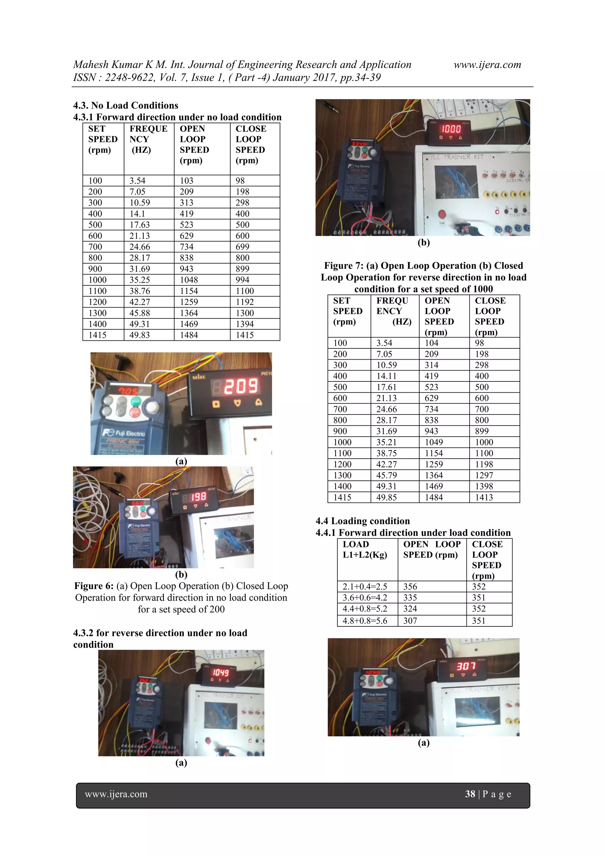
(b)
Figure 8: (a) Open Loop Operation (b) Closed Loop
Operation for forward direction in load condition
4.4.2 Reverse direction under load condition
LOAD
L1+L2
(Kg)
OPEN
LOOP
SPEED
(rpm)
CLOSE
LOOP
SPEED
(rpm)
0.6+0.6=1.2 1481 1406
1.5+0.9=2.4 1473 1407
2.5+1.2=3.7 1462 1406
3.8+1.7=55 1450 1409
(a)
(b)
Figure 9: (a) Open Loop Operation (b) Closed Loop
Operation for reverse direction in load condition for
a set speed of 1415rpm theoretically
V.CONCLUSIONS
The developed hardware and software has
been tested for its validity under various operating
conditions. We observed that both the hardware and
software coordinated and were in close relation.
To validate, the drive has been tested for
various operating conditions. Under closed loop
condition when the input command is set to a speed
of 1415 RPM the output speed recorded will be
around 1406 RPM (in digital display meter).
Experiments were repeated for different speeds and
results were found to be closed to the set value.
VI.FUTURE ENHANCEMENT
Motor speed can be controlled and multiple
motors can also be controlled with required
modification in the software and Torque control can
be implemented.
REFERENCE
[1]. Ahmed, Irfan (ed.). [1991]. Digital Control
Applications With the TMS320 Family, Texas
Instruments, Dallas, TX, 1991.
[2]. J.R. Hendershot, Jr. and T.J.E. Miller, Design
of three phase Induction Motors, Magna
Physics Publishing and Clarendon Press,
Oxford, U.K., 1994.
[3]. Microcontroller based speed control of three
phase induction motor using v/f method.
International Journal of Scientific and
Research Publications, Volume 3, Issue 2,
February 2013
[4]. V/F Speed Control of 3 phase Induction
Motor using Space Vector Modulation
[5]. by Ms.Priya Subhash Raichurkar,
International Journal of Engineering Research
& Technology
[6]. T. Kenjo and S. Nagamori, Three phase
induction Motors, Clarendon Press,
Oxford,U.K., 1985.
[7]. Three phase induction motor speed controller
using PLC approach by Yogini B. Hirave,
Prof. R.T. Patil, Mrs KetanBagade,
International Journal of Engineering Science
Invention.
[8]. Programmable logic controllers ,5th
edition-
W Bolton.
[9]. Power Electronics-Dr P S Bimbhra.](https://image.slidesharecdn.com/h0701043439-170131092034/75/Speed-Control-of-Three-Phase-Induction-Motor-Using-PLC-under-Open-and-Closed-Loop-Condition-6-2048.jpg)

The document discusses the speed control of three-phase induction motors using programmable logic controllers (PLC) under both open and closed loop conditions, highlighting the significance of automation in industrial applications. It explains the advancements in variable speed drives and the role of PLCs in improving motor performance through efficient dynamic control. The paper details various speed control techniques, experimental results, and the implementation of a system utilizing encoders for feedback in the motor operation.