Download to read offline
![(IJACSA) International Journal of Advanced Computer Science and Applications,
Vol. 11, No. 7, 2020
Modeling and Performance Analysis of an Adaptive
PID Speed Controller for the BLDC Motor
Md Mahmud1
*, S. M. A. Motakabber2
*, A. H. M. Zahirul Alam3
, Anis Nurashikin Nordin4
, A. K.M. Ahasan Habib5
Department of Electrical and Computer Engineering
International Islamic University Malaysia
Kuala Lumpur, Malaysia
Abstract—Brushless Direct Current (BLDC) motor is the
most popular useable motor for automation and industry. For
good performance of the BLDC motor hunger driving circuit but
the driving circuit is costly, complex control mechanism, various
parameter dependency and low torque. The Proportional
Integral (PI), Proportional Integral Derivative (PID), fuzzy logic,
adaptive, Quantity Feedback Theory (QFT), Pulse Width
Modulation (PWM) controller are the common types of control
method existing for the BLDC motor. This research explores
some well-working experiments and identified the PID controller
as far more applicable controller. For well efficacious and useful
in getting satisfied control performance if the adaptability is
implemented. This research proposed a combined method using
PID and PID auto tuner, having the ability to improve the system
adaptability, given the method named as adaptive PID controller.
To verify the performance, MATLAB simulation platform was
used, and a benchmark system was developed based on the actual
BLDC motor parameters, auxiliary systems, and mathematically
solved parameters. All work has done by using MATLAB/
Simulink.
Keywords—QFT; PWM; BLDC motor; PID controller;
adaptive; adaptive PID controller; APIDC
I. INTRODUCTION
Brushless DC motor is getting more popular and
operational motor than the other DC motor. It requires less
maintenance and can have a life span as it has no wearable
brush and has level speed-torque properties, high productivity.
In driving, from an assortment of motors, BLDC motors have
been generally utilized in automated, restorative hardware,
vehicles, aviation, hard circle drive, as the benefits of BLDC
are extraordinary execution, advance and lower assurance in
power factor. The BLDC motors are increasingly costly, and its
controller design is more complex [1]. Also, need to focus on
BLDC motor safety and inverter because it delivers a high risk
of security issues, demagnetization problem and inverter
disappointment. Controlling the motor speed of the BLDC
requires the controller circuit framework for good productivity.
Numerous kinds of speed control frameworks have been
produced for controllers, yet speed controllers must be
refreshed with age. Right now, there are two circles for speed
control of the BLDC motor. For instance, the electronic force
motor speed controller for the inward circle tuning and an
outside circle for inverter permits the very voltage of the DC
vehicle [2]. To control this framework, the DC supply required
relies upon the motor RPM and its capacities. The sensor is the
most significant piece of the controller for controlling the
motor speed. The sensor can stream directions. The inverter
used to change over DC voltage to AC voltage likewise has a
DC voltage converter to change over DC to this framework. In
any case, when utilizing a brush dc motor, mechanical rubbing,
and electrical erosion mess some up which urge the inclination
to utilize brushless dc (BLDC) motor. These days, BLDC
motors are generally utilized in electronic vehicles, because the
nonattendance of a brush/transport gathering decreases hearing
sharpness and improves productivity and torque [3]. A well-
known magnet brushless DC motor (PMBDCM) is mainstream
and utilized BLDC motor utilized as a variable speed drive
framework for mechanical, car, aviation, and computerization
applications. The rotor is made electronically rather than a
stator and a permanent magnet and computation brushless.
There are two types of brushless motor: Namely, brushless AC
motor and brushless DC motor. The brushless AC motor
(perpetual magnet simultaneous motor) and the brushless DC
motor rely upon the current frequency. The brushless AC
motor is consumed by the sinusoidal current while the
brushless DC motor is consumed by the rectangular stream [4].
Studies have been directed to quantify force swell in brushless
DC motor [5]. It is unordinary for papers to depict the
estimation of electromagnetic force delivered by a brushless
DC motor utilizing current stage information. Motor force can
be estimated straightforwardly by a force sensor which can be
costly and can now and again be overwhelming when applied
to explicit applications. Assessments of electromagnetic force
with quantifiable limits, for example, back EMF, rotor speed
and stage current are deeply alluring [6]. The electromagnetic
force of a brushless DC motor can be assessed by estimating
the stage movements by asserted that in any event two current
sensors were expected to assess the electromagnetic force.
Initially, these procedures were utilized legitimately as BLDC
motor controllers. Immediately, the FLC was applied to control
the speed of the BLDC motor [7]. It is described by its capacity
to manage inadequately characterized numerical models. The
FLC rules required to make control directions rely to a great
extent upon the human experience. Notwithstanding, FLCs
require additional time than regular control strategies, for
example, PI and PID to determine complex fuzzification and
cleansing procedures [8]. In this research applied two types
controller one is PID controller another one is PID-Auto tuner
both are combined, and it called adaptive PID controller. This
study aims to develop a controller drive to control BLDC
motor speed and torque and compare controller output result
with benchmark controller. This works done by using
MATLAB/ Simulink.
*Corresponding Author
272 | P a g e
www.ijacsa.thesai.org](https://image.slidesharecdn.com/000007-211028000533/85/000007-1-320.jpg)
![(IJACSA) International Journal of Advanced Computer Science and Applications,
Vol. 11, No. 7, 2020
This article is organized into five distinct sections. After the
abstract, the article starts with the introduction as Section I
discusses BLDC motor and its control system. Section II
introduces and discusses the basic models of a BLDC motor
and speed control systems. In Section III, the method and the
MATLAB simulation model are discussed in detail. Section IV
is illustrated by graphical results obtained from MATLAB
models of Section III. Finally, this research article is concluded
by a conclusion, Section number V.
II. BASIC MODEL AND SPEED CONTROL OF BLDC MOTOR
Fig. 1 shows the basic model of the Adaptive PID
controller. To develop motor controlling controller many
scholars, follow the different method and technic. In this
research also apply another technic to increase the motor speed.
For better output efficiency of the BLDC, motor speed control
is very impotent in this situation. So, solved this problem and
get better efficiency proposed this basic model. The
motherboard has a three-triode power converter, as it conveys
six force transistors all the while on a BLDC motor. The
MOSFET transistors have a rotor position, which will be
characterized as the exchanging succession. The starter is the
objective of each of the three gadget gadgets. The Hall sensor
is the data that the decoder square creates in the EMF of the
reference current sign vector. Enacting the switch side of the
invert flows for the contrary side of the moving motor.
Fig. 1. Basic Block Diagram of an Adaptive PID Controller.
III. CONTROLLER AND RESEARCH METHOD
The proposed controller was simulated by the MATLAB
simulation process, but the controller needs to develop
mathematical equations and monitor the performance of
simulation-based.
A. Proposed Adaptive-PID Controller
The Adaptive PID auto-tuner is the combined controller,
that working in a series of PID and PID auto-tuner controller.
This combination of the combined controller has the
adaptability over any circumstances, as like the increasing
number of input decision change. The Adaptive PID auto-tuner
block is containing both controllers in series. In Fig. 2, the
Adaptive PID auto-tuner controller is shown with the motor
transfer function and inside the Adaptive PID auto-tuner
controller block, where both controllers are connected in series.
B. FPA based BLDC Speed Controller, Benchmark Paper
One of the researches has done on Flower Pollination
Algorithm (FPA) for speed control of BLDC motor with
optimal PID tuning [9]. In that work, the optimization-based
approach is applied for tuning of PID speed controller by
considering an integral square error as the objective function.
This model also followed the cascade mode, the speed control
loop and voltage control loop. Both controllers followed the
PID basic controller inside where FPA method algorithm was
developed. Though the method looks good, on the benchmark
platform it was giving overshoot which is higher than a normal
phenomenon. Fig. 3 shows the FPA speed controller.
C. Equations
The model of the armature contorting for the BLDC motor
is communicated as pursues:
𝑣𝑎 = 𝑅𝑖𝑎 + 𝐿
𝑑𝑖𝑎
𝑑𝑡
+ 𝑒𝑎 (1)
𝑣𝑏 = 𝑅𝑖𝑏 + 𝐿
𝑑𝑖𝑏
𝑑𝑡
+ 𝑒𝑏 (2)
𝑣𝑐 = 𝑅𝑖𝑐 + 𝐿
𝑑𝑖𝑐
𝑑𝑡
+ 𝑒𝑐 (3)
where L is armature self-inductance [H], R - armature
resistance (Ω), va, vb, vc - terminal phase voltage (V ), ia, ib, ic
- motor input current (A), and ea, eb, ec - motor back-emf (V).
The equivalent circuit for one phase is represented in Fig. 4. In
the 3-stage BLDC motor, the back-emf is identified with an
element of rotor position and the back-emf of each stage has
120 degrees stage point distinction so the condition of each
stage ought to be as per the following:
ea = Kef (θe) ω (4)
eb = Kef (θe − 120) ω (5)
ec = Kef (θe + 120) ω (6)
(a)
(b)
Fig. 2. MATLAB Model (a) Adaptive PID Auto-Tuner Controller in Close-
Loop System and (b) Inside Adaptive PID Auto-Tuner Block.
Fig. 3. The FPA based Controller for BLDC.
273 | P a g e
www.ijacsa.thesai.org](https://image.slidesharecdn.com/000007-211028000533/85/000007-2-320.jpg)
![(IJACSA) International Journal of Advanced Computer Science and Applications,
Vol. 11, No. 7, 2020
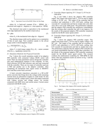
Fig. 7. Output of the Adaptive PID Controller Applying 48V.
TABLE II. SIMULATED MEASUREMENTS FOR 1000 RPM
Measurements Time
Rising time 31.386 ms
Max / Min high 1001 RPM /993.939 RPM
With load maximum high 999.3 RPM
Overshoot 0.452%
With load overshoot 0.197%
With load undershoot 1.833%
C. FPA Speed Control System, Applying 48V, Torque Te
10N-m for 1000 RPM
The Flower Pollination Algorithm (FPA) also one of the
popular controllers already describes in Fig. 3. This controller
is one of the smooth performance controllers, can be used for
any slow process system. Fig. 8 shows the performance of the
FPA controller performance. The controller gave 1098 RPM
having unexcitable overshoot of 9.34%. While applied load, it
again gave 3.646% undershoot, but with time smoothly came
back to the required line. When, the sudden load applied to the
system, immediately a high undershoot and overshoot formed
due to its slow response. This response is not only for this
system, but most of the research also found the same issue. The
controller is perfect for a system, where slow response and
steady performance is required. The performance specifications
are given in Table III for better understanding.
TABLE III. FPA BASED SPEED CONTROLLER PERFORMANCE ON THE
SIMULATION PLATFORM
Measurements Time
Rise time (With load) 0.03415s
Max / Min high (Without load) 1098 RPM / 998.7 RPM
Max / Min high (With load) 1038 RPM / 994.5 RPM
Without load RMS 1003 RPM
With load RMS 1001 RPM
Without load overshoot 9.34%
With load undershoot 3.646%
Fig. 8. FPA Speed Controller Output Applying 48V.
D. Compare with Benchmark Controller
Fig. 9 shows the adaptive PID controller output and FPA
speed controller output. This output with load condition and its
supply voltage is 48 volts. Reference rpm is 1000 after running
the output of the adaptive PID controller had an overshoot of
0.197% and undershoot is 1.833% (48V/unit), settling time
0.05 seconds (seconds/unit) and had no steady-state error. On
the other hand, the FPA speed controller had an overshoot of
9.34% and undershoot is 3.646% (48V/unit), settling time is
unknown and had a steady-state error. The performance
indicates that the adaptive PID controller has good
controllability than the existing others So, The results of the
proposed adaptive PID controller simulation model for the
BLDC motor speed control. The Pre-shoot, overshoot and
undershoot can be reduced mainly by using a high-frequency
noise and filter [10].
Fig. 9. Adaptive PID and PFA Speed Controller, Applying 48V, Te-10 N-m.
V. CONCLUSION
This controller design for three-phase BLDC motor for its
speed control. An adaptive PID controller technology has more
advanced to control BLDC motor. As a result, an adaptive PID
controller gives excellent Simulation results than the other
275 | P a g e
www.ijacsa.thesai.org](https://image.slidesharecdn.com/000007-211028000533/85/000007-4-320.jpg)
![(IJACSA) International Journal of Advanced Computer Science and Applications,
Vol. 11, No. 7, 2020
controller system. However, it is worth noticing that when the
motor functions at up and down speeds, for it to be well
responsive, the motor speed must be continuous when the load
will change. This research aims almost completed but still need
to remove it noise for smooth speed control. The aims of the
study will be developed a Prototype control drive using this
adaptive PID controller to control BLDC motor speed. This
simulation work helps to developed BLDC motor speed and
efficiency.
VI. FUTURE WORK
This research primarily has been developed a basic
foundation of the proposed adaptive PID speed controller for
the BLDC motor, and verified the design by simulation
successfully. Further experimental tests can be conducted in
the future for a detailed evaluation of this research and to
further strengthen the claim of its achievement.
ACKNOWLEDGMENT
This research has been supported by the Malaysian
Ministry of Education through the Fundamental Research
Grant Scheme under the project ID: FRGS19-054-0662.
REFERENCES
[1] P. Yedamale, “Brushless DC (BLDC) motor fundamentals”, Microchip
Technology Inc, 20, pp.3-15, 2003.
[2] H. B. Wang, H. P. Liu, “A novel sensorless control method for brushless
DC motor,” IET Electr. Power Appl, Vol. 3(3), pp. 240–246, May 2009.
[3] M. V. Rajkumar, G. Ranjhitha, M. Pradeep and M. F. Kumar, “Fuzzy-
based Speed Control of Brushless DC Motor feed electric vehicle”,
IJISSET, vol. 3(3), 2017.
[4] N. Hashemnia and B. Asaei, "Comparative study of using different
electric motors in the electric vehicles," 2008 18th International
Conference on Electrical Machines, Vilamoura, 2008, pp. 1-5, doi:
10.1109/ICELMACH.2008.4800157.
[5] D. C. Hanselman, "Minimum torque ripple, maximum efficiency
excitation of brushless permanent magnet motors," in IEEE
Transactions on Industrial Electronics, vol. 41, no. 3, pp. 292-300, June
1994, doi: 10.1109/41.293899.
[6] M. Mahmud, S. M. A. Motakabber, A. H. M. Z. Alam, A. N. Nordin,
“Adaptive PID controller using for speed control of the BLDC motor”,
2020 IEEE International Conference on Semiconductor Electronics
(ICSE),2020.
[7] L. Sun, H. Gao, Q. Song, J. Nei, "Measurement of torque ripple in PM
brushless motors," Conference Record of the 2002 IEEE Industry
Applications Conference. 37th IAS Annual Meeting (Cat.
No.02CH37344), Pittsburgh, PA, USA, vol. 4, pp. 2567-2571, 2002. doi:
10.1109/IAS.2002.1042808.
[8] J. Shen, Z. Zhu, D. Howe, and J. Buckley, "Fuzzy logic speed control
and current-harmonic reduction in permanent magnet brushless ac
drives," IEE Proceedings-Electric Power Applications, vol. 152(3), pp.
437-446, 2005.
[9] D. Potnuru, D., “Experimental implementation of Flower Pollination
Algorithm for speed controller of a BLDC motor”, Ain Shams
Engineering Journal, Vol. 10(2), pp. 287–295, 2019.
[10] M. Mahmud, S. M. A. Motakabber, A. H. M. Z. Alam, A. N. Nordin,
“Control BLDC Motor Speed using PID Controller”, International
Journal of Advanced Computer Science and Applications(IJACSA),
Vol.11(3), pp. 477-481, 2020.
276 | P a g e
www.ijacsa.thesai.org](https://image.slidesharecdn.com/000007-211028000533/85/000007-5-320.jpg)

This document summarizes a research paper that proposes an adaptive PID speed controller for a brushless DC motor. The paper begins with an introduction to brushless DC motors and common speed control methods like PI, PID, fuzzy logic and PWM controllers. It then discusses developing an adaptive PID controller that combines a PID controller with an auto-tuning method. This allows the controller to adapt to changing system parameters. The paper describes modeling the BLDC motor and speed control systems in MATLAB/Simulink. Simulation results are presented and analyzed to verify the adaptive PID controller's performance. The adaptive PID controller is found to improve system adaptability compared to other control methods.


![[000011]](https://cdn.slidesharecdn.com/ss_thumbnails/000011-211028000834-thumbnail.jpg?width=640&height=640&fit=bounds)
![[000008]](https://cdn.slidesharecdn.com/ss_thumbnails/000008-211028000724-thumbnail.jpg?width=640&height=640&fit=bounds)


 (2)](https://cdn.slidesharecdn.com/ss_thumbnails/tugasbesarkikifebrian2018310040112-200630011627-thumbnail.jpg?width=640&height=640&fit=bounds)


