This report discusses the principle and operation of centrifugal pumps, which convert rotational kinetic energy into hydrodynamic energy for fluid transport in various applications such as sewage and petroleum pumping. Key components include the impeller, casing, and shaft, and the report also outlines different types of centrifugal pumps, their advantages, disadvantages, and efficiency metrics. Additionally, the document includes historical background, specifications, and energy usage considerations related to centrifugal pumps.


![14
molecules [source: Discovery]. Under those extreme conditions, the gas fully dissolves
in the liquid.
The temperature of water at carbonation is also critical. Water that's carbonated at near-
freezing temperature (32 degrees Fahrenheit or 0 degrees Celsius) can hold five times
as much C02as water that's carbonated at 140 degrees F (60 degrees C).
Inside the pressure chamber, carbonated water has absolutely no fizz. The bubbles only
emerge when the liquid is released from the chamber back into normal atmospheric
pressure. Carbonated water contains 16,000 times more C02than regular water, roughly
five "glasses" of C02 for every glass of water. When you pop the cap on a soda bottle,
the release of pressure causes all of those dissolved C02 molecules to become gas again
and rush to escape through the surface of the liquid as bubbles.
Figure 5: Soda Fountain machine
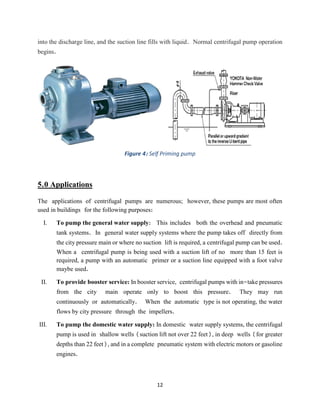
VIII. In Household work: Centrifugal pumps are used in buildings for pumping the general
water supply, as a booster and for domestic water supplies.
IX. In Sewage system: The design of a centrifugal pump makes them useful
for pumping sewage and slurries.
X. For controlling process: They are also used in fire protection systems and for heating
and cooling applications.
6.0 Specifications
Centrifugal pumps are commonly rated by horsepower, flow rate, outlet pressure in metres (or
feet) of head, inlet suction in suction feet (or metres) of head. The head can be simplified as](https://image.slidesharecdn.com/part24-170727021228/85/Special-study-on-Centrifugal-Pump-14-320.jpg)


![30
constructed for a specific range of applications. Equipped with well selected anti wear systems
and materials in combination with reasonable maintenance, a long lifespan can be met.
13.0 References
[1] Ladislao Reti, “Francesco di Giorgio (Armani) Martini's Treatise on Engineering and Its
Plagiarists”, Technology and Culture, Vol. 4, No. 3. (Summer, 1963), pp. 287-298 (290)
[2] James Thomson (Dec. 23, 1859). "Professor Thomson's Centrifugal Pump". The
Mechanics' magazine, and journal of engineering, agricultural machinery, manufactures and
shipbuilding (Robertson, Brooman, & Co.) II: 408–410.
[3] John Richards (1894). Centrifugal pumps: an essay on their construction and operation,
and some account of the origin and development in this and other countries
(http://books.google.com/books?id=013VAAAAMAAJ&pg=PA41). The Industrial
Publishing Company.p. 40–41.
[4] Markus Reiner (14 April 1960). "A centripetal air pump"
(http://books.google.com/books?id=9x-5Nx7OqHoC&pg=PA946). NewScientist 7
(178): 946. .
[5] Charles F. Conaway (1999). The petroleum industry:
anontechnicalguide(http://books.google.com/books?id=sJ7BO1cCD20C&pg=SA8-PA52).
PennWell Books. p. 200. ISBN9780878147632.
[6] Pete Melby (1995). Simplified Irrigation Design
(http://books.google.com/books?id=raxr9AbTgFwC&pg=PA145) (2nd ed.). John Wiley
and Sons. p.145. ISBN 9780471286226.
[7] R. K. Bansal (2005). A textbook of fluid mechanics and hydraulic machines
(http://books.google.com/books?id=nCnifcUdNp4C&pg=PA938) (9th ed.). Firewall
Media. p. 938.ISBN 9788170083115.](https://image.slidesharecdn.com/part24-170727021228/85/Special-study-on-Centrifugal-Pump-30-320.jpg)


![Seminar presentation (2) 24 (3)v[1].pptx](https://cdn.slidesharecdn.com/ss_thumbnails/seminarpresentation22431-250419171925-bad1f7f9-thumbnail.jpg?width=640&height=640&fit=bounds)


![Seminar presentation (2) 24 (2)[1].pptxvftfcutyjbhmjl](https://cdn.slidesharecdn.com/ss_thumbnails/seminarpresentation22421-250326170405-96c80d8c-thumbnail.jpg?width=640&height=640&fit=bounds)


