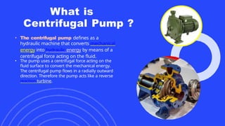
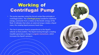
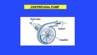
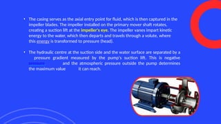
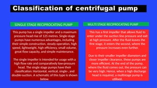
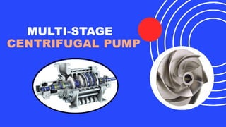
CENTRIFUGAL
PUMP
TABLE OF CONTENT
• Centrifugal Pump.
• Parts of Centrifugal Pump.
• Working of Centrifugal pump
• Classification of centrifugal pump based
on
number of stages.
• Multi stage centrifugal pump.
• Components of Multistage
centrifugal Pump.
• Performance and characterstic of
Multi stage centrifugal pump
• Working of Multistage Centrifugal
What is
Centrifugal Pump ?
• The centrifugal pump defines as a
hydraulic machine that converts mechanical
energy into hydraulic energy by means of a
centrifugal force acting on the fluid.
• The pump uses a centrifugal force acting on the
fluid surface to convert the mechanical energy.
The centrifugal pump flows in a radially outward
direction. Therefore the pump acts like a reverse
reaction turbine.
PARTS OF
CENTRIFUGAL
PUMP
1. Shaft with Shaft Sleeve
The shaft is the main component of the pump which rotates with the
attached impeller. The shaft is coupled with the ball bearings that facilitate
the rotation. This assembly is attached to a sleeve which is called a shaft
sleeve. It is used to shield the shaft from corrosion and leaks by sealing the
opening of the sleeve.
2. Impeller
The term impeller refers to a wheel or rotor with a series of vanes or backward-curved blades. It is connected to an
electric motor's shaft. This is the rotating portion of the pump contained in a watertight casing. The rotation of an
impeller imparts velocity to a fluid.
The impeller of a centrifugal pump can be categorized into three major types as discussed below:
1. Open Impeller: The vanes of an open impeller are attached to a central hub which is mounted directly to the shaft.
Since no walls or covers surround the vanes, open impellers are weaker than closed ones.
2. Closed Impeller: This type consists of back and front cover plates between which the vanes are usually sandwiched.
These impellers have double or single inlets and are commonly installed in radial flow pumps.
3. Semi-Open Impeller: A back-wall cover plate on semi-open impellers powers the van mechanically while leaving the
other side open. Medium-sized pumps employ semi-open impellers.
4. Casing
The casing of the pump is an airtight chamber that encloses the impeller. It is constructed to convert the kinetic
energy of the water discharged at the outlet to pressure energy before entering the delivery pipe. The casing is
also of three types which are discussed below.
•Volute Casing: This kind of casing has an impeller surrounding it. Such a casing offers a gradual rise in the flow
area, which increases water pressure and decreases its velocity.
•Vortex Casing: A circular chamber is inserted between the casing and the impeller. The fluid generated by the
impeller passes through the vortex chamber, followed by the volute casing. The vortex casing has a higher
efficiency than the volute casing.
• Casing with Guide Blades: The impeller is surrounded by the blades in this casing. These blades are positioned
to allow water from the impeller to enter the guide vane without shock and eventually arrive at the delivery with
increased pressure.
2. Suction Pipe
The suction pipe of the pump usually consists of two ends. One end dips
into a sump with water and the other end is connected to the inlet of the
pump. To stop foreign objects from entering the suction pipe, a strainer
is also installed at one end of the pipe
3. Delivery Pipe
The delivery pipe is also made of two ends, but one end of this pipe
is connected to the outlet of the pump while the other end delivers
water to the desired height or head.
Working of
Centrifugal Pump
• The pump operates using the forced vortex flow principle or
centrifugal action. The centrifugal pump transforms rotational
energy, commonly from a motor, to the kinetic energy of the
fluid. It indicates that when an external torque rotates a liquid
mass, the rotating liquid pressure head rises.
• The rise in pressure head is proportional to the liquid's
velocity at that position. The liquid moving through a rotating
impeller generates a change in angular momentum, which
increases the liquid's pressure.
CENTRIFUGAL PUMP
• The casing serves as the axial entry point for fluid, which is then captured in the
impeller blades. The impeller installed on the primary mover shaft rotates,
creating a suction lift at the impeller's eye. The impeller vanes impart kinetic
energy to the water, which then departs and travels through a volute, where
this energy is transformed to pressure (head).
• The hydraulic centre at the suction side and the water surface are separated by a
pressure gradient measured by the pump's suction lift. This is negative
pressure, and the atmospheric pressure outside the pump determines
the maximum value it can reach.
Classification of centrifugal pump
This pump has a single impeller and a maximum
pressure head rise of 125 metres. Single-stage
pumps have numerous advantages, including
their simple construction, steady operation, high
speed, lightweight, high efficiency, small volume,
great flow capacity, and simple maintenance.
The single impeller is intended for usage with a
high flow rate and comparatively low-pressure
head. The single stage pumps have their
classification: Horizontal, vertical, single-, and
double-suction. A schematic of this type is shown
below.
This has a first impeller that allows fluid to
enter under the suction line pressure and exit
at high pressure. After the fluid leaves the
first stage, it enters the second, where the
pressure increases even further.
Due to their smaller impeller diameters and
closer impeller clearance, these pumps are
more efficient. At the end of the pump,
where the fluid comes out, the pressure can
be very high. Hence, when a high discharge
head is required, a multistage pump is
utilised.
SINGLE STAGE RECIPROCATING PUMP MULTI STAGE RECIPROCATING PUMP
MULTI-STAGE
CENTRIFUGAL PUMP
ERFORMANCE CHARACTERS
TIC OF
MULTI STAGE
CENTRIFUGA
LPUMP
1: Multi-stage pump is mainly used for mine drainage, city
and factory water supply.
2: Compared with reciprocating pumps such as piston pumps
and diaphragm pumps, it can also pump larger flow rates.
3: The multi-stage centrifugal pump has high efficiency, can meet
the needs of high lift and high flow conditions, and has been
widely used in petrochemical, chemical, electric power,
construction, fire protection and other industries.
4: Due to its particularity, compared with single-stage
centrifugal pumps, multi-stage centrifugal pumps have
different and higher technical requirements in terms of
design, use, maintenance and repair.
WORKING
PRINCIPLE OF
MULTI STAGE
CENTRIFUGALPUMP
1: Compared with single-stage pumps, multi-stage centrifugal
pumps have the difference that multi-stage pumps have more
than two impellers, which can absorb water and pressurize water
in stages in multiple stages, thus lifting water to a high position
The number of pump impeller stages can be increased or
decreased according to need.
2: There are two types of multistage centrifugal pumps, vertical
and horizontal
3: The pump shaft of the multistage centrifugal pump is
equipped
with two impellers connected in series
4: Compared with the general single-stage centrifugal pump,
the multi-stage pump can also achieve a higher head.
MULTI STAGE CENTRIFUGAL PUMP
Thank you
Brita Tamm
502-555-0152
brita@firstupconsultants.com
www.firstupconsultants.com

Centrifugal pump presentation for engineering

  • 2.
  • 3.
    TABLE OF CONTENT •Centrifugal Pump. • Parts of Centrifugal Pump. • Working of Centrifugal pump • Classification of centrifugal pump based on number of stages. • Multi stage centrifugal pump. • Components of Multistage centrifugal Pump. • Performance and characterstic of Multi stage centrifugal pump • Working of Multistage Centrifugal
  • 4.
    What is Centrifugal Pump? • The centrifugal pump defines as a hydraulic machine that converts mechanical energy into hydraulic energy by means of a centrifugal force acting on the fluid. • The pump uses a centrifugal force acting on the fluid surface to convert the mechanical energy. The centrifugal pump flows in a radially outward direction. Therefore the pump acts like a reverse reaction turbine.
  • 5.
    What is Centrifugal Pump? • The centrifugal pump defines as a hydraulic machine that converts mechanical energy into hydraulic energy by means of a centrifugal force acting on the fluid. • The pump uses a centrifugal force acting on the fluid surface to convert the mechanical energy. The centrifugal pump flows in a radially outward direction. Therefore the pump acts like a reverse reaction turbine.
  • 6.
    PARTS OF CENTRIFUGAL PUMP 1. Shaftwith Shaft Sleeve The shaft is the main component of the pump which rotates with the attached impeller. The shaft is coupled with the ball bearings that facilitate the rotation. This assembly is attached to a sleeve which is called a shaft sleeve. It is used to shield the shaft from corrosion and leaks by sealing the opening of the sleeve.
  • 7.
    2. Impeller The termimpeller refers to a wheel or rotor with a series of vanes or backward-curved blades. It is connected to an electric motor's shaft. This is the rotating portion of the pump contained in a watertight casing. The rotation of an impeller imparts velocity to a fluid. The impeller of a centrifugal pump can be categorized into three major types as discussed below: 1. Open Impeller: The vanes of an open impeller are attached to a central hub which is mounted directly to the shaft. Since no walls or covers surround the vanes, open impellers are weaker than closed ones. 2. Closed Impeller: This type consists of back and front cover plates between which the vanes are usually sandwiched. These impellers have double or single inlets and are commonly installed in radial flow pumps. 3. Semi-Open Impeller: A back-wall cover plate on semi-open impellers powers the van mechanically while leaving the other side open. Medium-sized pumps employ semi-open impellers. 4. Casing The casing of the pump is an airtight chamber that encloses the impeller. It is constructed to convert the kinetic energy of the water discharged at the outlet to pressure energy before entering the delivery pipe. The casing is also of three types which are discussed below. •Volute Casing: This kind of casing has an impeller surrounding it. Such a casing offers a gradual rise in the flow area, which increases water pressure and decreases its velocity. •Vortex Casing: A circular chamber is inserted between the casing and the impeller. The fluid generated by the impeller passes through the vortex chamber, followed by the volute casing. The vortex casing has a higher efficiency than the volute casing. • Casing with Guide Blades: The impeller is surrounded by the blades in this casing. These blades are positioned to allow water from the impeller to enter the guide vane without shock and eventually arrive at the delivery with increased pressure.
  • 8.
    2. Suction Pipe Thesuction pipe of the pump usually consists of two ends. One end dips into a sump with water and the other end is connected to the inlet of the pump. To stop foreign objects from entering the suction pipe, a strainer is also installed at one end of the pipe 3. Delivery Pipe The delivery pipe is also made of two ends, but one end of this pipe is connected to the outlet of the pump while the other end delivers water to the desired height or head.
  • 9.
    Working of Centrifugal Pump •The pump operates using the forced vortex flow principle or centrifugal action. The centrifugal pump transforms rotational energy, commonly from a motor, to the kinetic energy of the fluid. It indicates that when an external torque rotates a liquid mass, the rotating liquid pressure head rises. • The rise in pressure head is proportional to the liquid's velocity at that position. The liquid moving through a rotating impeller generates a change in angular momentum, which increases the liquid's pressure.
  • 10.
  • 11.
    • The casingserves as the axial entry point for fluid, which is then captured in the impeller blades. The impeller installed on the primary mover shaft rotates, creating a suction lift at the impeller's eye. The impeller vanes impart kinetic energy to the water, which then departs and travels through a volute, where this energy is transformed to pressure (head). • The hydraulic centre at the suction side and the water surface are separated by a pressure gradient measured by the pump's suction lift. This is negative pressure, and the atmospheric pressure outside the pump determines the maximum value it can reach.
  • 12.
    Classification of centrifugalpump This pump has a single impeller and a maximum pressure head rise of 125 metres. Single-stage pumps have numerous advantages, including their simple construction, steady operation, high speed, lightweight, high efficiency, small volume, great flow capacity, and simple maintenance. The single impeller is intended for usage with a high flow rate and comparatively low-pressure head. The single stage pumps have their classification: Horizontal, vertical, single-, and double-suction. A schematic of this type is shown below. This has a first impeller that allows fluid to enter under the suction line pressure and exit at high pressure. After the fluid leaves the first stage, it enters the second, where the pressure increases even further. Due to their smaller impeller diameters and closer impeller clearance, these pumps are more efficient. At the end of the pump, where the fluid comes out, the pressure can be very high. Hence, when a high discharge head is required, a multistage pump is utilised. SINGLE STAGE RECIPROCATING PUMP MULTI STAGE RECIPROCATING PUMP
  • 13.
  • 14.
    ERFORMANCE CHARACTERS TIC OF MULTISTAGE CENTRIFUGA LPUMP 1: Multi-stage pump is mainly used for mine drainage, city and factory water supply. 2: Compared with reciprocating pumps such as piston pumps and diaphragm pumps, it can also pump larger flow rates. 3: The multi-stage centrifugal pump has high efficiency, can meet the needs of high lift and high flow conditions, and has been widely used in petrochemical, chemical, electric power, construction, fire protection and other industries. 4: Due to its particularity, compared with single-stage centrifugal pumps, multi-stage centrifugal pumps have different and higher technical requirements in terms of design, use, maintenance and repair.
  • 15.
    WORKING PRINCIPLE OF MULTI STAGE CENTRIFUGALPUMP 1:Compared with single-stage pumps, multi-stage centrifugal pumps have the difference that multi-stage pumps have more than two impellers, which can absorb water and pressurize water in stages in multiple stages, thus lifting water to a high position The number of pump impeller stages can be increased or decreased according to need. 2: There are two types of multistage centrifugal pumps, vertical and horizontal 3: The pump shaft of the multistage centrifugal pump is equipped with two impellers connected in series 4: Compared with the general single-stage centrifugal pump, the multi-stage pump can also achieve a higher head.
  • 16.
  • 17.