Downloaded 112 times

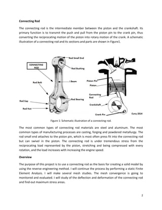
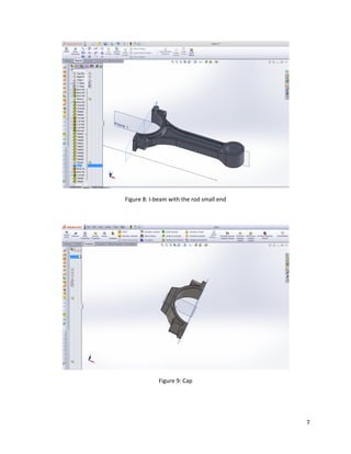
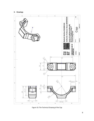
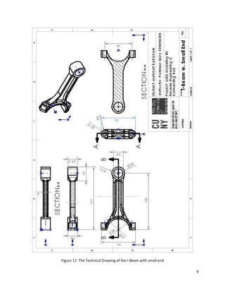
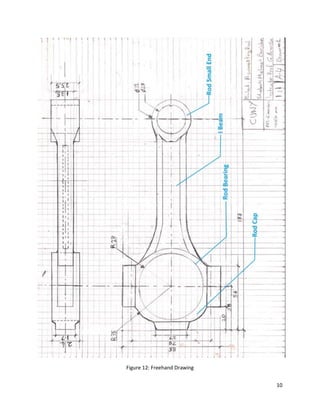
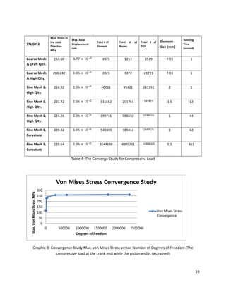
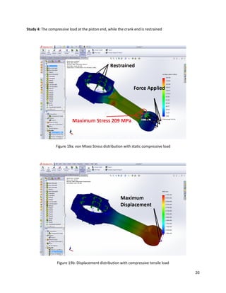
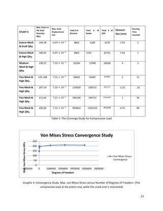
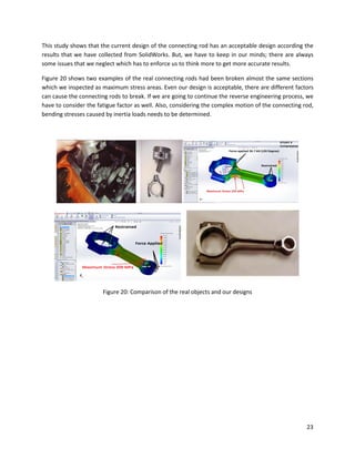


This document summarizes a student's solid modeling project to create a computer-aided design (CAD) model of a connecting rod through reverse engineering. The student followed these steps: 1) Creating a freehand sketch of the connecting rod using measurements; 2) Developing a solid model in SolidWorks based on the sketch; 3) Creating technical drawings of the model; 4) Performing a finite element analysis to evaluate stresses and deformation under load. The analysis found the highest stresses occurred near where loads were applied. Though within safety factors, real connecting rods can still break due to unmodeled factors like fatigue not considered.


![ME 312 Mechanical Machine Design [Screws, Bolts, Nuts]](https://cdn.slidesharecdn.com/ss_thumbnails/me312-dsulec10-screws-170213050612-thumbnail.jpg?width=640&height=640&fit=bounds)


![[IJET-V1I3P7] Authors : Prateek Joshi, Mohammad UmairZaki](https://cdn.slidesharecdn.com/ss_thumbnails/ijet-v1i3p7-150520112457-lva1-app6892-thumbnail.jpg?width=640&height=640&fit=bounds)