Download to read offline

![International Research Journal of Engineering and Technology (IRJET) e-ISSN: 2395-0056
Volume: 07 Issue: 03 | Mar 2020 www.irjet.net p-ISSN: 2395-0072
© 2020, IRJET | Impact Factor value: 7.34 | ISO 9001:2008 Certified Journal | Page 1016
⸫ Stiffness = Weight / Deformation
= 16914.88634 N/m or 16.91488634 N/mm
By above specified calculations the values for above other
materials were found to be safe for applicationofconnecting
rod and specified in the table given below;
Table 4 - Result obtained by theoretical analysis.
Stresses
Materials
Titanium
Alloy
Forged Steel
Aluminum
360
σm
(Mpa)
318.4847 330.84077 315.06632
σy (Mpa) 1207 415 170
σv (Mpa) 318.2552 330.65923 314.82368
σe (Mpa) 362.1 124.5 51
Stiffness
(N/m)
4765.7029 16914.8863 1849.7553
F.O.S 1.985 3.453 8.026.
9. CONCLUSION AND FUTURE SCOPE
1. Solid modeling of connecting rod was made in NX
10 according to design procedure usedandanalysis
under the effect of tensile and compressive loads in
terms of pressure is done in ANSYS Workbench.
2. From analysis it is observed that the minimum
stresses among all loadingconditions,werefoundat
crank end cap as well as at piston end. So the
material can be reduced from those portions,
thereby reducing material cost.
3. For further optimization of material dynamic
analysis of connecting rod is needed. After
considering dynamic load conditions once again
finite element analysis will have to be performed. It
will give more accurate results than existing.
4. From the static analysis the stress is found
maximum at the small end of the connecting rod.
5. Forged steel as a connecting rod material islessstiff
and having more weight than forged steel andother
material taking in consideration.
6. Forged steel connecting rod is having more weight
than Aluminium, magnesium and beryllium alloys
connecting rod.
7. Aluminium alloy connecting rod is having more
weight and displacement than magnesium and
beryllium alloys. So, aluminum connecting rod
shows more shaky behavior.
8. Maximum von mises stress, Maximum von mises
strain and Maximum displacement are minimum in
connecting rod of Beryllium alloy.
9. Other than conventional materials used the above
studied material can be also used as they show
greater quality than the conventional material.
10. The only thing that is barrier to implement ofabove
materials is costing, availability of material and its
repairing.
Future Scope
The above work is presented on static analysis of
connecting rod and has many aspects to research
further as follows
1. Torsional analysis can be done due to presence of
small amount of torsional momentatthe endpoints.
2. Design modification can be done to minimize the
weight of connecting rod and the inertia force.
3. Work on the internal coating of hardmaterial inside
the both ends can be done to minimize the wear
failure in connecting rod.
4. Development of connecting rod using different
techniques and above stated materials can be
manufactured and experimental and dynamic
analysis can be carried out.
5. Fatigue analysis can also be carried out on material
having high quality and cost so as to improve and
define life of connecting rod.
REFERENCES
[1] Kuldeep B, Arun L.R, Mohammed Faheem “ANALYSIS
AND OPTIMIZATION OF CONNECTING ROD USING ALFASiC
COMPOSITES”, ISSN: 2319- 875, International Journal of
Innovative ResearchinScience,Engineeringand Technology,
Vol. 2, Issue 6, June 2013
[2] Prof. N.P.Doshi, 1 Prof .N.K.Ingole “ANALYSIS OF
CONNECTING ROD USING ANALYTICAL AND FINITE
ELEMENT METHOD”
INTERNATIONAL JOURNAL OF MODERN ENGINEERING
RESEARCH” (IJMER) www.ijmer.com Vol.3, Issue.1, Jan Feb.
2013, ISSN: 2249-6645.
[3] Yoo et al., M.M. Rahman, M.M. Noor, K. Kadirgama and
A.K. Amirruddin “DESIGN OF CONNECTING ROD OF
INTERNAL COMBUSTION ENGINE: ATOPOLOGY
OPTIMIZATION APPROACHM” National Conference in
Mechanical Engineering Research and Postgraduate Studies
(2nd NCMER 2010) 3-4 December 2010, pp.155166
[4] FOLGAR Analysis of Connecting RodUsingAnalytical and
Finite Element‟ International Journal ofModernEngineering
Research (IJMER), JanFeb. 2013, Vol.3, Issue.1, pp-65-68
BIOGRAPHIES
Mr. Hrishikesh D. Nitturkar
Diploma in Mechanical Engg.
Student, Dept. of Mechanical
Engineering, BSIET College,
Kolhapur, Maharashtra, India.](https://image.slidesharecdn.com/irjet-v7i3189-201205022633/75/IRJET-Design-and-Analysis-of-Connecting-Rod-using-Different-Materials-6-2048.jpg)

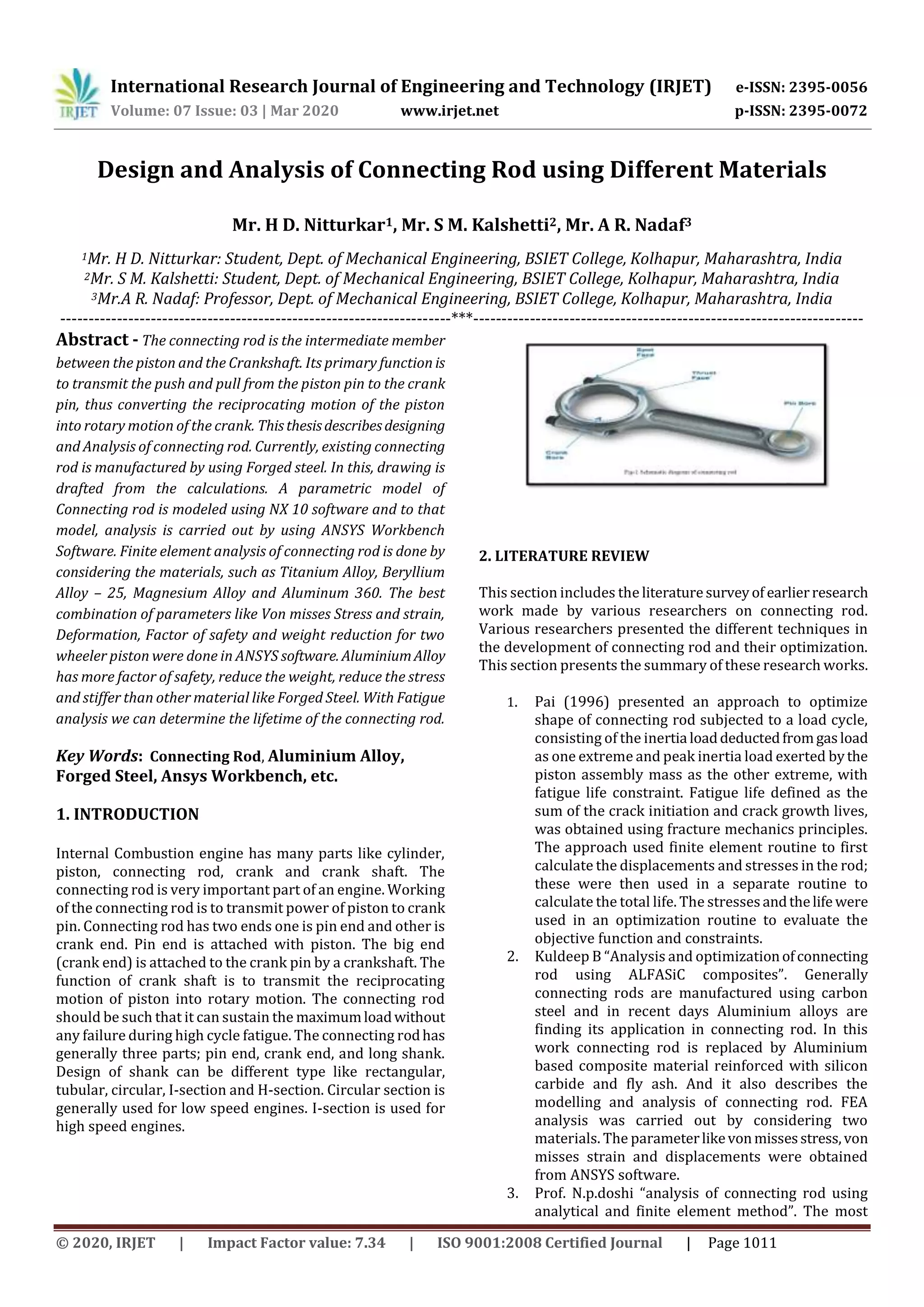
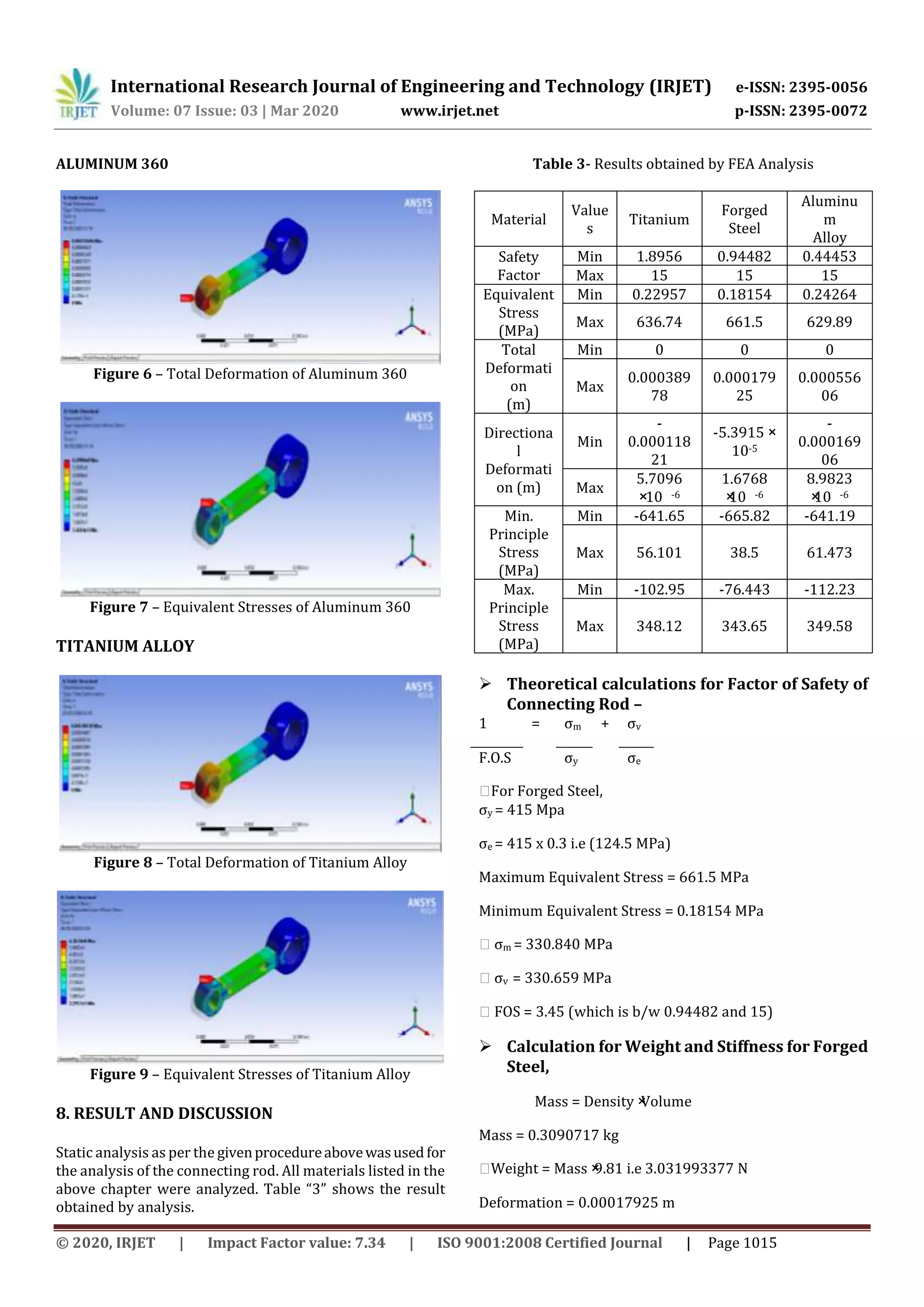
This document describes the design and analysis of a connecting rod using different materials through finite element analysis. The connecting rod was modeled in NX 10 software and analyzed in ANSYS Workbench. Materials analyzed included titanium alloy, beryllium alloy, magnesium alloy, and aluminum 360. ANSYS was used to analyze von mises stress, strain, deformation, factor of safety, and weight reduction for each material. Aluminum alloy was found to have a higher factor of safety, lower weight, lower stress, and was stiffer than forged steel. Fatigue analysis can also determine the lifetime of the connecting rod. The connecting rod was designed, modeled, and analyzed to compare the performance of different materials.


![[IJET-V1I3P7] Authors : Prateek Joshi, Mohammad UmairZaki](https://cdn.slidesharecdn.com/ss_thumbnails/ijet-v1i3p7-150520112457-lva1-app6892-thumbnail.jpg?width=640&height=640&fit=bounds)