Downloaded 356 times


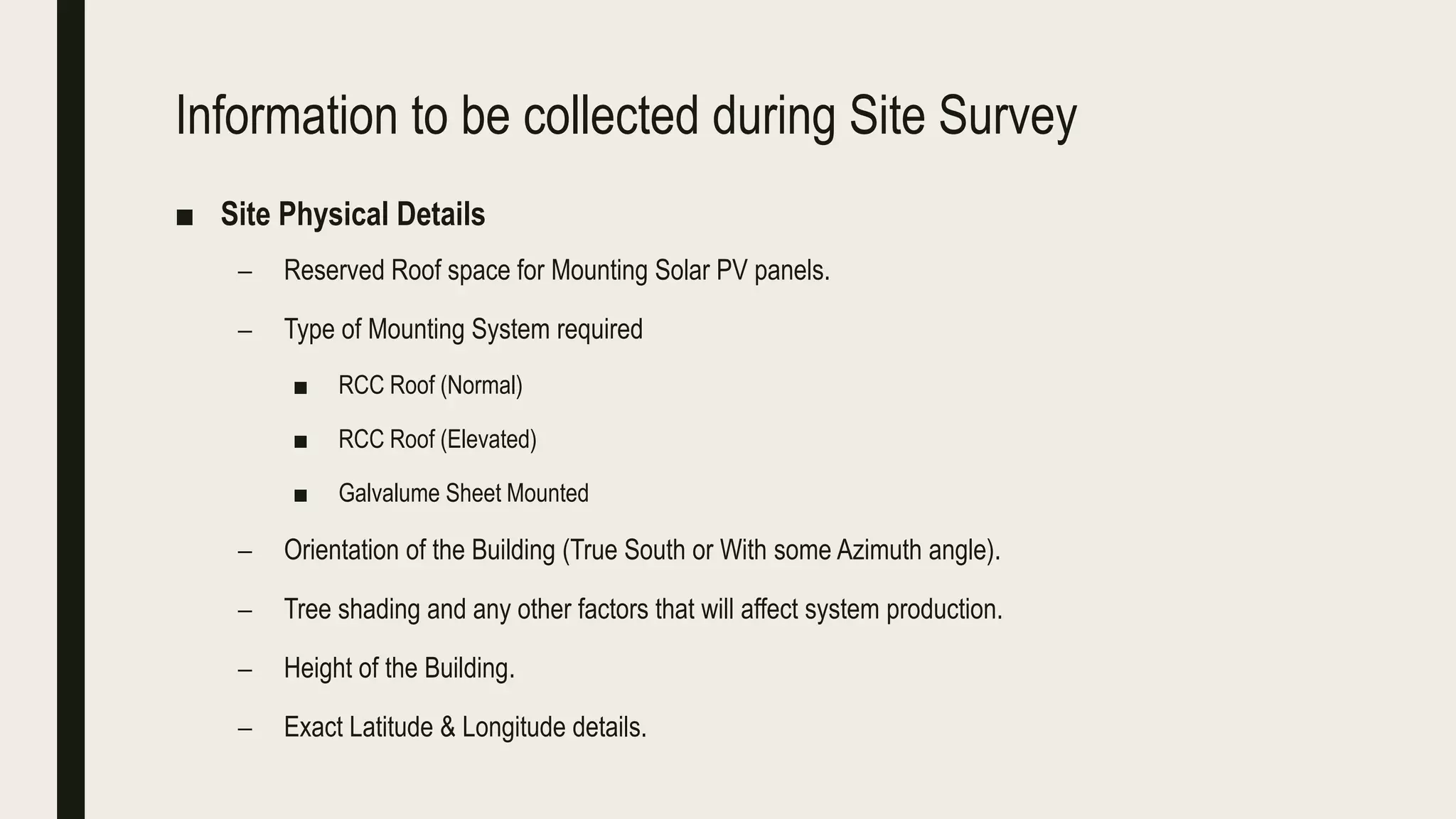


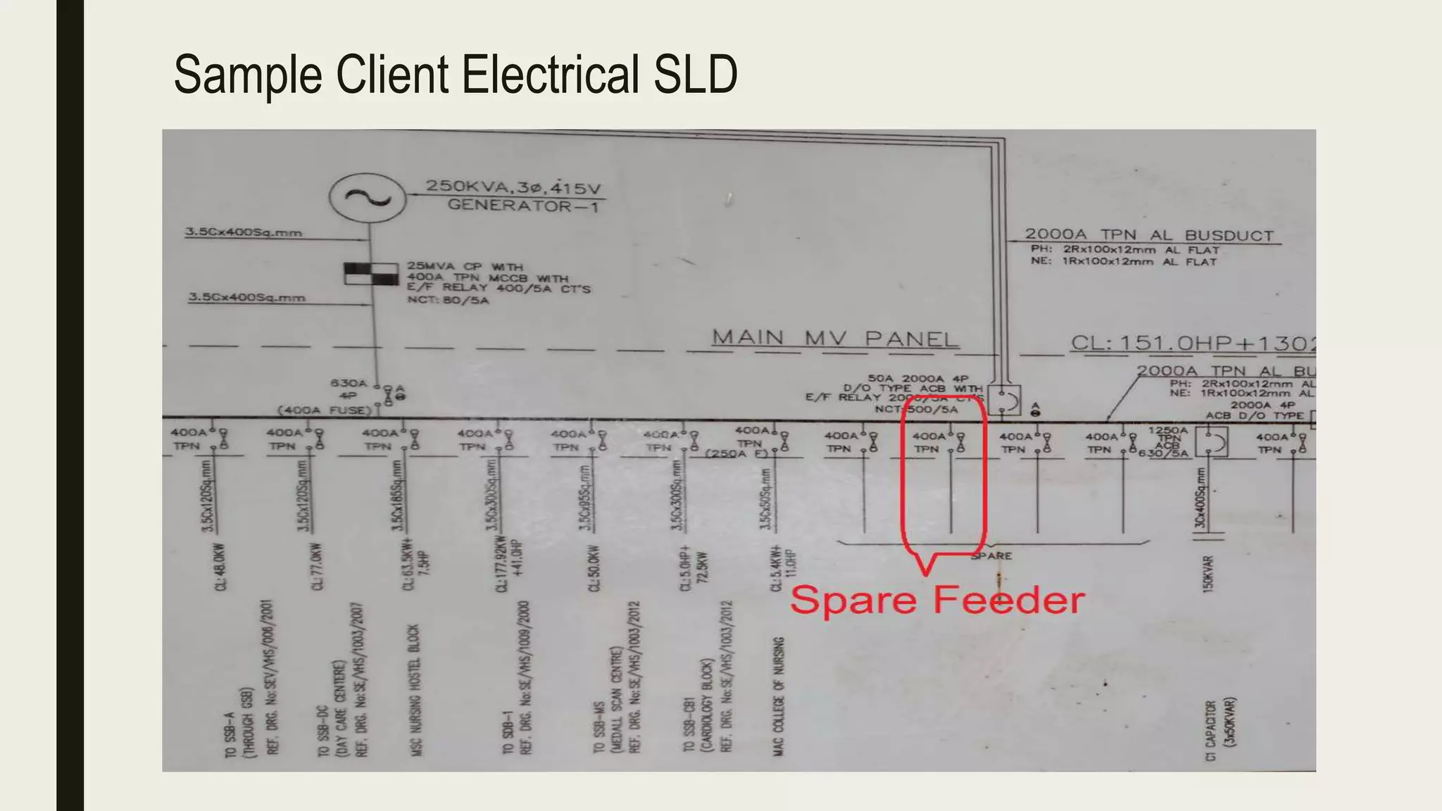

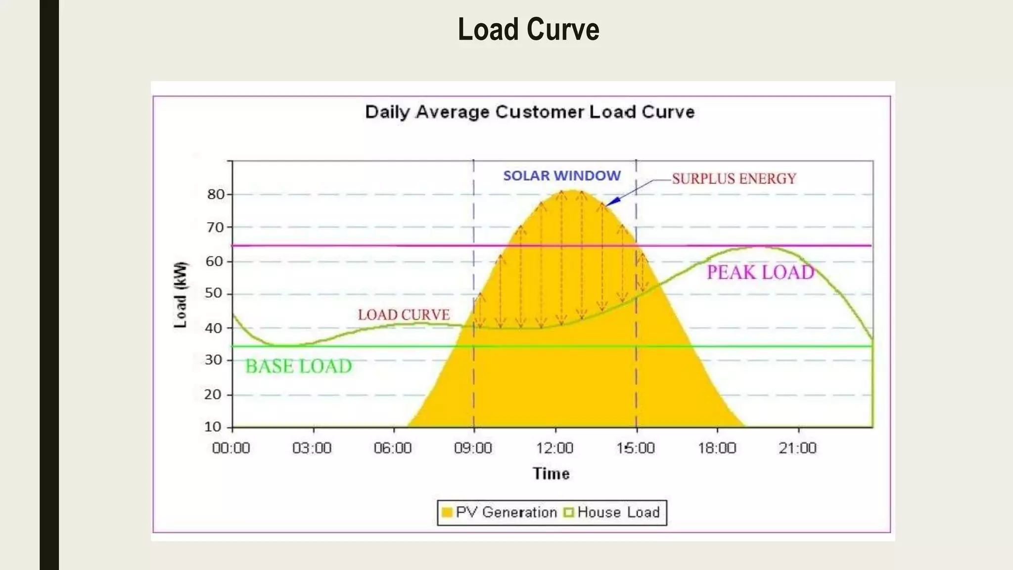

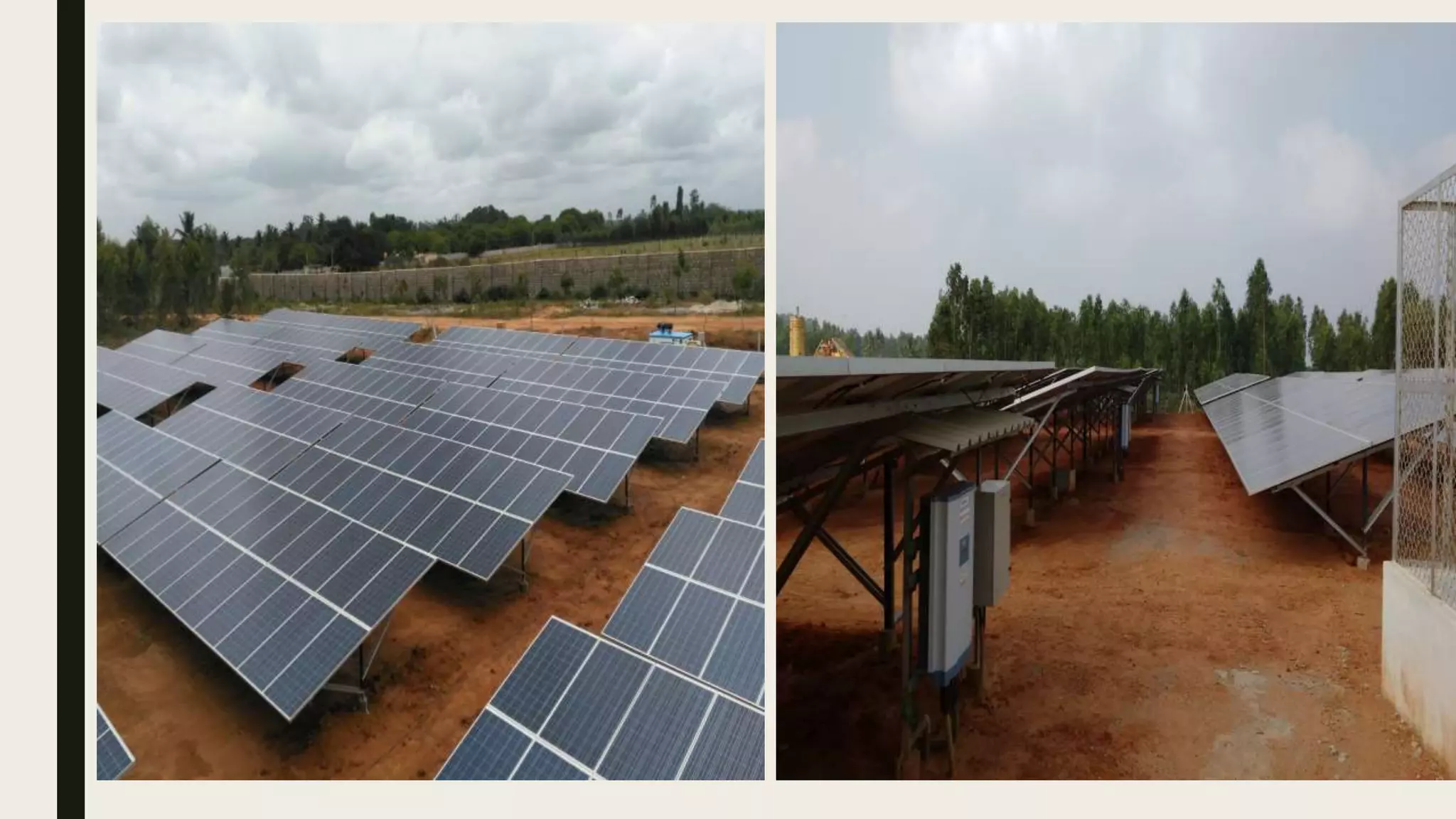


The solar feasibility study document discusses the key steps and information needed to conduct a solar feasibility study for both rooftop and ground-mounted solar PV projects. The feasibility study involves collecting site details like available roof or land space, structure details, electrical load details, and interfacing voltage requirements. This information is used to design the optimal solar PV system configuration and ensure any issues are addressed. Component placement, cable routing and distances are also determined to prepare an accurate bill of materials and system cost estimate.


