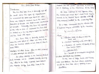
VIVEKANANDHA COLLEGE OF TECHNOLOGY
FOR WOMEN
DEPARTMENT OF CIVIL ENGINEERING
CE8703-STRUCTURAL DESIGN AND DRAWING
By
Mr.A.ANANTHAKUMAR, M.E.,(Ph.D).,
Assistant Professor
CE8703 STRUCTURAL DESIGN AND DRAWING L T P C 3 0 2 4
OBJECTIVE:
This course aims at providing students with a solid background on the principles of
structural engineering design. Students will be acquire the knowledge of liquid retaining
structures, bridges components, retaining wall and industrial structures.
• UNIT I RETAINING WALLS 9+6
Reinforced concrete Cantilever and Counter fort Retaining Walls–Horizontal Backfill with
Surcharge–Design of Shear Key-Design and Drawing.
• UNIT II FLAT SLAB and BRIDGES 9+6
Design of Flat Slabs with and without drops by Direct Design Method of IS code- Design
and Drawing - IRC Specifications and Loading – RC Solid Slab Bridge – Steel Foot-over
Bridge- Design and Drawing.
• UNIT III LIQUID STORAGE STRUCTURES 9+6
RCC Water Tanks - On ground, Elevated Circular, underground Rectangular Tanks–
Hemispherical Bottomed Steel Water Tank –Design and Drawing
• UNIT IV INDUSTRIAL STRUCTURES 9+6
Structural steel Framing - Steel Roof Trusses – Roofing Elements – Beam columns –
Codal provisions - Design and Drawing.
• UNIT V GIRDERS AND CONNECTIONS 9+6
Plate Girders – Behaviour of Components-Deign of Welded Plate Girder-Design of
Industrial Gantry Girders – Design of Eccentric Shear and Moment Resisting connections.
INTRODUCTION
Flat slab Flat slab with drop panels
Flat slab with column head Flat slab with drop panel and column head
INTRODUCTION
Uses of column heads :
• increase shear strength of slab
• reduce the moment in the slab by reducing
the clear or effective span
Flat slab with column head
INTRODUCTION
Uses of drop panels :
• increase shear strength of slab
• increase negative moment capacity of slab
• stiffen the slab and hence reduce deflection
2015-2016 2
Flat slabs:
Concrete slabs may be carried directly by columns as shown in Fig.(1-1) without the use
of beams or girders. Such slabs are described as flat plates and are commonly used where
spans are not large and loads not particularly heavy.
Slab
1
Col.
Col
drop
Fig.(1-1) Slab supported directly on column.
At point (1) there is more (-M) and shearing stress, and col. try to punch the slab.
Flat slab construction shown in Fig.(1-2) is also beamless but incorporates a thickened
slab region (drop panels) and column capitals.
slab
Col. Capital
Fig.(1-2) Flat slab.
2015-2016 3
Column capital: An element at the end of the column to give a wider support for the
floor slab
Column capital and drop panel are used to reduce: 1- Stresses
due to shear.
2- Negative bending around the columns.
Size of drop panel shall be in accordance with the following ACI-code (8.2.4 –ACI-
2014). Drop panel shall be extended in each direction from center line of support a
distance not less than one-sixth the span length measured from center to center of
supports in that direction.
The side of the drop panel shall be at least (L/3),
Where
L: (c. to.c)
t: Thickness of slab
t1:Thickness of slab with drop
t2:Thickness of drop
t t2 ≥
4
2015-2016 4
Bending moments in flat slab floors:
For purposes of design, a typical panel is divided into column strips and middle strips.
ACI-2014 (8.4.1.5) column strip is a design strip with a width on each side of a column
centerline equal to (0.25l1) or (0.25l2), whichever is less. Column strip includes beams,
if any.
In all cases
l1: is the span in the direction of the moment analysis (c. to c.).
l2: is the span in the lateral direction (transvers tol1c.to.c).
ln: clear span in l1direction.
2015-2016 5
l1 direction Panels (1,2,3,7,8,9) Exterior slab
Panels (4,5,6) Interior slab
l2 direction Panels (1,4,7,3,6,9) Exterior slab
Panels (2,5,8) Interior slab
In case of flat slab the column strip is more critical than middle strip because it work as
beam carrying the middle strip load to the column therefore column strip need more
reinforcement. Plus that the beam takes 85% of the slab moment in the case of two-way
slab with beams.
panel
panel panel
2015-2016 6
1
(M + M
2 8
ab cd e f u 2 n
) + M =
1
w l l2
A similar requirement exists in the perpendicular direction.
Deflection control of two-way slab:
Design limits (ACI-code 2014):
Minimum slab thickness:
8.3.1.1 For nonprestressed slabs without interior beams spanning between supports on all
sides, having a maximum ratio of long-to-short span of 2, overall slab thickness h shall
not be less than the limits in Table 8.3.1.1 and shall be at least the value in (a) or (b)
unless the calculated deflection limits of 8.3.2 are satisfied:
(a) Slabs without drop panels as defined in 8.2.4..............................125 mm.
(b) Slabs with drop panels as defined in 8.2.4 ..................................100 mm.
2015-2016 7
8.3.1.2 For nonprestressed slabs with beams spanning between supports on all sides,
overall slab thickness h shall satisfy the limits in Table 8.3.1.2 unless the calculated
deflection limits of 8.3.2 are satisfied.
2015-2016 8
Direct design method of two way slabs (8.10.2 ACI-2014):
Limitations:
Moments in two-way slab can be found using direct design method subject to the
following restrictions:
1. There shall be at least three continuous spans in each direction.
2.Successive span lengths measured center-to-center of supports in each direction shall
Prof. Dr. Mustafa B. Dawood Dr. Bilal Ismaeel Al-Shraify
2015-2016 9
3.Panels shall be rectangular, with a ratio of longer to shorter panel dimensions measured
center-to-center of supports, not exceed 2.
4.Columns offset shall not exceed 10 percent of the span in direction of offset from either
axis between centerlines of successive columns.
5.All loads shall be due to gravity only and uniformly distributed over an entire panel.
6.Unfactored live load shall not exceed two times the unfactored dead load.
L. L
D. D
≤ 2.0
8.10.2.1 For a panel with beams between supports on all sides, Eq. (8.10.2.7a) shall be
satisfied for beams in the two perpendiculardirections
αf1l2
1
αf2l2
0.2 ≤ 2
≤ 5.0 (8.10.2.7a)
Where αf1andαf2are calculatedby:
f
α = E I
cb b
EcsIs
(8.10.2.7b)
αf1=αf in directionl1
αf2=αf in direction l2
In the case of monolithic construction (two-way slab with beams)
Single side slab Symmetric slab
2015-2016 10
f
α =
E I
cb b
EccIs c
, I = f
l2ℎ3
12
For internal strip l 2 = SA+SB
2
For external strip l 2 = SA
+ c
2 2
Total static moment for end span
o
M = u 2 n
w l l2
8
l1 = la ln →l1
ln → clear span face to face of columns, capitals, brackets orwalls.
ln ≥ 0.65 l1
For other direction:
End span
Interior span
End span
Panel Panel
2015-2016 11
For internal strip l 2 = Sa+Sb
2
For external strip l 2 = Sa
+ c
2 2
Total static moment for end span, Mo = u 2 n w SS2
8
l1 = lÆ ln → l1
ln: Clear span, circular or regular polygon shaped support shall be treated as square
support with the same area.
Panel
Panel
End span Int span End span
2015-2016 12
Negative and positive factored moment:
For interior span (8.10.4.1):
Negative Mu = 0.65Mo
Positive Mu = 0.35 Mo
For end span:
Use Table 8.10.4.2 (ACI-2014)
2015-2016 13
8.10.4.5 Negative moment Mu shall be the greater of the two negative Mu calculated for
spans framing into a common support unless an analysis is made to distribute the
unbalanced moment in accordance with stiffnesses of adjoining elements.
beam
slab
Exterior
Prof. Dr. Mustafa B. Dawood Dr. Bilal Ismaeel Al-Shraify
Interior
2015-2016 14
Factored moments in column strips
8.10.5.1 The column strips shall resist the portion of interior negative Mu in accordance
with Table 8.10.5.1.
8.10.5.2 The column strips shall resist the portion of exterior negative Mu in accordance
with Table 8.10.5.2.
Slab with beams between supports
2015-2016 15
The relative restrained provided by the torsional resistance of the effective transverse
edge beam is reflected by the parameter þt, defined as:
t
2EccIc
EcbC
þ = (8.10.5.2a)
The constant C for T- or L- section is calculated by dividing the section into separate
rectangular parts, each having smaller dimension (x) and larger dimension (y), and
summing the values of C for each part.
C = Σ (1 − 0.63
y
)
x (x3y)
3 (8.10.5.2b)
The subdivision can be done in such away as to maximize C.
8.10.5.5 The column strips shall resist the portion of positive Mu in accordance with
Table 8.10.5.5.
2015-2016 16
Factored moments in beams
8.10.5.7.1 Beams between supports shall resist the portion of column strip Mu in
accordance with Table 8.10.5.7.1.
Direct loads on beams:- factored beam self-weight + factored wall weight
(wu)b = (ℎ − ℎf)bw ∗ 24 ∗ 1.2 + wall weigℎt ∗ 1.2
o b
(M ) =
(w ) l2
8
u b n
, n
l = clear sean for bean
Interior beam
Total negative moment = 0.85 col. Strip moment + 0.65 (Mo)b Total pos.
moment = 0.85 col. Strip moment + 0.35 (Mo)b
2015-2016 17
End beam (Use Table 8.10.4.2):
Internal negative moment = 0.85 col. Strip moment + factor (Mo)b pos. moment
= 0.85 col. Strip moment + factor (Mo)b
External neg. moment = 0.85 col. Strip moment + factor (Mo)b
Design of moment reinforcement for slab
m
ρ = [1 − J 1 − u
1 2R m
fy u
] , R =
Mu
∅bd2
fy
m = As = ρ ∗ bd
0.85 ∗ fcu
Asmin = 0.002 Ag for fy < 420N/mm2
Asmin =
0.0018 ∗ 420
fy
N
for fy ≥ 420
mm2 or Asmin = 0.0014Ag
Smain = As(provided by one bar)
total As (req. ) ∗ width of strip
Smax =2t(2hf)
2015-2016 18
þ1
Dr. Bilal Ismaey
þ2
Ex
t.
2015-2016 19
Prof. Dr. Mustafa B. Dawood Dr. Bilal Ismaeel Al-Shraify
Important Questions
1. Design an interior panel of a flat slab in a hotel carrying a superimposed
live load of 3kN/m2 . Weight of floor finishes on the slab may be taken
as 2 kN/m2. The panel is supported on 300mm diameter circular. Drops
may be provided. The size of panel is 5mx7m. Adopt M20 concrete and
Fe415 steel.
2. An interior panel of a flat slab floor is 6mx6m along column centre lines.
Live load on floor is 3kN/m2. Supporting column diameter is 500mm.
Choosing the thickness of the slab (from stiffness criteria) and
appropriate dimensions for column head and drops, calculate the design
moments and shear forces. Use direct design method.
3. Design an interior panel of a flat slab for a live load of 5kN/m2 and a
column grid of 6mx6m. Columns are of 600mm diameter. Drops shall be
provided. Show the reinforcement details in the flat slab. Use M20
concrete and Fe415 steel.
4. Design a interior panel flat using following data dimension of the
panel 5mx5m size of the floor 25mx25m, imposed load 4kN/m2,
using M20 and Fe415 steel.
5.A flat slab floor is proposed for an office 25mx20m, column grid =
5mx4m, live load = 6kN/m2. Materials = M20 grade concrete
&Fe415 HYSD bars. Design an interior plane to support this load
and sketch the reinforcement details.
6. A simply supported RC slab is required for the deck of a road
bridge having the data given below;
Width of carriage way = 7.5m
Width of kerb = 600mm
Clear span = 5m
Width of bearing = 400mm
Type of loading : IRC class AA or A, whichever gives the worst
effect. Materials : M20 grade concrete ; Fe415 grade HYSD bars.
7. Design on RC slab culvert for a national highway to suit the following data;
A two lane carriage way = 8m wide
Foot paths on either side = 1m wide
Clear span = 7m
Wearing coat = 100mm
Width of bearing = 500mm
Materials : M25 grade concrete & Fe415 grade HYSD bars.
Loading : IRC class AA tracked vehicle.
Design the RC deck slab and sketch the details of reinforcements in the
longitudinal and cross sections of the slab.
8. Design on RC slab culvert for a national highway to suit the following data;
A two lane carriage way = 5m wide
Foot paths on either side = 500mm wide
Clear span = 6m
Wearing coat = 150mm
Width of bearing = 700mm
Materials : M20 grade concrete & Fe415 grade HYSD bars.
Loading : IRC class AA tracked vehicle.
Design the RC deck slab and sketch the details of reinforcements in the
longitudinal and cross sections of the slab.
THANK YOU…
Stay Home… Save Life…

Design of Flat Slab and Bridges

  • 1.
    VIVEKANANDHA COLLEGE OFTECHNOLOGY FOR WOMEN DEPARTMENT OF CIVIL ENGINEERING CE8703-STRUCTURAL DESIGN AND DRAWING By Mr.A.ANANTHAKUMAR, M.E.,(Ph.D)., Assistant Professor
  • 2.
    CE8703 STRUCTURAL DESIGNAND DRAWING L T P C 3 0 2 4 OBJECTIVE: This course aims at providing students with a solid background on the principles of structural engineering design. Students will be acquire the knowledge of liquid retaining structures, bridges components, retaining wall and industrial structures. • UNIT I RETAINING WALLS 9+6 Reinforced concrete Cantilever and Counter fort Retaining Walls–Horizontal Backfill with Surcharge–Design of Shear Key-Design and Drawing. • UNIT II FLAT SLAB and BRIDGES 9+6 Design of Flat Slabs with and without drops by Direct Design Method of IS code- Design and Drawing - IRC Specifications and Loading – RC Solid Slab Bridge – Steel Foot-over Bridge- Design and Drawing. • UNIT III LIQUID STORAGE STRUCTURES 9+6 RCC Water Tanks - On ground, Elevated Circular, underground Rectangular Tanks– Hemispherical Bottomed Steel Water Tank –Design and Drawing • UNIT IV INDUSTRIAL STRUCTURES 9+6 Structural steel Framing - Steel Roof Trusses – Roofing Elements – Beam columns – Codal provisions - Design and Drawing. • UNIT V GIRDERS AND CONNECTIONS 9+6 Plate Girders – Behaviour of Components-Deign of Welded Plate Girder-Design of Industrial Gantry Girders – Design of Eccentric Shear and Moment Resisting connections.
  • 3.
    INTRODUCTION Flat slab Flatslab with drop panels Flat slab with column head Flat slab with drop panel and column head
  • 4.
    INTRODUCTION Uses of columnheads : • increase shear strength of slab • reduce the moment in the slab by reducing the clear or effective span Flat slab with column head
  • 5.
    INTRODUCTION Uses of droppanels : • increase shear strength of slab • increase negative moment capacity of slab • stiffen the slab and hence reduce deflection
  • 14.
    2015-2016 2 Flat slabs: Concreteslabs may be carried directly by columns as shown in Fig.(1-1) without the use of beams or girders. Such slabs are described as flat plates and are commonly used where spans are not large and loads not particularly heavy. Slab 1 Col. Col drop Fig.(1-1) Slab supported directly on column. At point (1) there is more (-M) and shearing stress, and col. try to punch the slab. Flat slab construction shown in Fig.(1-2) is also beamless but incorporates a thickened slab region (drop panels) and column capitals. slab Col. Capital Fig.(1-2) Flat slab.
  • 15.
    2015-2016 3 Column capital:An element at the end of the column to give a wider support for the floor slab Column capital and drop panel are used to reduce: 1- Stresses due to shear. 2- Negative bending around the columns. Size of drop panel shall be in accordance with the following ACI-code (8.2.4 –ACI- 2014). Drop panel shall be extended in each direction from center line of support a distance not less than one-sixth the span length measured from center to center of supports in that direction. The side of the drop panel shall be at least (L/3), Where L: (c. to.c) t: Thickness of slab t1:Thickness of slab with drop t2:Thickness of drop t t2 ≥ 4
  • 16.
    2015-2016 4 Bending momentsin flat slab floors: For purposes of design, a typical panel is divided into column strips and middle strips. ACI-2014 (8.4.1.5) column strip is a design strip with a width on each side of a column centerline equal to (0.25l1) or (0.25l2), whichever is less. Column strip includes beams, if any. In all cases l1: is the span in the direction of the moment analysis (c. to c.). l2: is the span in the lateral direction (transvers tol1c.to.c). ln: clear span in l1direction.
  • 17.
    2015-2016 5 l1 directionPanels (1,2,3,7,8,9) Exterior slab Panels (4,5,6) Interior slab l2 direction Panels (1,4,7,3,6,9) Exterior slab Panels (2,5,8) Interior slab In case of flat slab the column strip is more critical than middle strip because it work as beam carrying the middle strip load to the column therefore column strip need more reinforcement. Plus that the beam takes 85% of the slab moment in the case of two-way slab with beams. panel panel panel
  • 18.
    2015-2016 6 1 (M +M 2 8 ab cd e f u 2 n ) + M = 1 w l l2 A similar requirement exists in the perpendicular direction. Deflection control of two-way slab: Design limits (ACI-code 2014): Minimum slab thickness: 8.3.1.1 For nonprestressed slabs without interior beams spanning between supports on all sides, having a maximum ratio of long-to-short span of 2, overall slab thickness h shall not be less than the limits in Table 8.3.1.1 and shall be at least the value in (a) or (b) unless the calculated deflection limits of 8.3.2 are satisfied: (a) Slabs without drop panels as defined in 8.2.4..............................125 mm. (b) Slabs with drop panels as defined in 8.2.4 ..................................100 mm.
  • 19.
    2015-2016 7 8.3.1.2 Fornonprestressed slabs with beams spanning between supports on all sides, overall slab thickness h shall satisfy the limits in Table 8.3.1.2 unless the calculated deflection limits of 8.3.2 are satisfied.
  • 20.
    2015-2016 8 Direct designmethod of two way slabs (8.10.2 ACI-2014): Limitations: Moments in two-way slab can be found using direct design method subject to the following restrictions: 1. There shall be at least three continuous spans in each direction. 2.Successive span lengths measured center-to-center of supports in each direction shall Prof. Dr. Mustafa B. Dawood Dr. Bilal Ismaeel Al-Shraify
  • 21.
    2015-2016 9 3.Panels shallbe rectangular, with a ratio of longer to shorter panel dimensions measured center-to-center of supports, not exceed 2. 4.Columns offset shall not exceed 10 percent of the span in direction of offset from either axis between centerlines of successive columns. 5.All loads shall be due to gravity only and uniformly distributed over an entire panel. 6.Unfactored live load shall not exceed two times the unfactored dead load. L. L D. D ≤ 2.0 8.10.2.1 For a panel with beams between supports on all sides, Eq. (8.10.2.7a) shall be satisfied for beams in the two perpendiculardirections αf1l2 1 αf2l2 0.2 ≤ 2 ≤ 5.0 (8.10.2.7a) Where αf1andαf2are calculatedby: f α = E I cb b EcsIs (8.10.2.7b) αf1=αf in directionl1 αf2=αf in direction l2 In the case of monolithic construction (two-way slab with beams) Single side slab Symmetric slab
  • 22.
    2015-2016 10 f α = EI cb b EccIs c , I = f l2ℎ3 12 For internal strip l 2 = SA+SB 2 For external strip l 2 = SA + c 2 2 Total static moment for end span o M = u 2 n w l l2 8 l1 = la ln →l1 ln → clear span face to face of columns, capitals, brackets orwalls. ln ≥ 0.65 l1 For other direction: End span Interior span End span Panel Panel
  • 23.
    2015-2016 11 For internalstrip l 2 = Sa+Sb 2 For external strip l 2 = Sa + c 2 2 Total static moment for end span, Mo = u 2 n w SS2 8 l1 = lÆ ln → l1 ln: Clear span, circular or regular polygon shaped support shall be treated as square support with the same area. Panel Panel End span Int span End span
  • 24.
    2015-2016 12 Negative andpositive factored moment: For interior span (8.10.4.1): Negative Mu = 0.65Mo Positive Mu = 0.35 Mo For end span: Use Table 8.10.4.2 (ACI-2014)
  • 25.
    2015-2016 13 8.10.4.5 Negativemoment Mu shall be the greater of the two negative Mu calculated for spans framing into a common support unless an analysis is made to distribute the unbalanced moment in accordance with stiffnesses of adjoining elements. beam slab Exterior Prof. Dr. Mustafa B. Dawood Dr. Bilal Ismaeel Al-Shraify Interior
  • 26.
    2015-2016 14 Factored momentsin column strips 8.10.5.1 The column strips shall resist the portion of interior negative Mu in accordance with Table 8.10.5.1. 8.10.5.2 The column strips shall resist the portion of exterior negative Mu in accordance with Table 8.10.5.2. Slab with beams between supports
  • 27.
    2015-2016 15 The relativerestrained provided by the torsional resistance of the effective transverse edge beam is reflected by the parameter þt, defined as: t 2EccIc EcbC þ = (8.10.5.2a) The constant C for T- or L- section is calculated by dividing the section into separate rectangular parts, each having smaller dimension (x) and larger dimension (y), and summing the values of C for each part. C = Σ (1 − 0.63 y ) x (x3y) 3 (8.10.5.2b) The subdivision can be done in such away as to maximize C. 8.10.5.5 The column strips shall resist the portion of positive Mu in accordance with Table 8.10.5.5.
  • 28.
    2015-2016 16 Factored momentsin beams 8.10.5.7.1 Beams between supports shall resist the portion of column strip Mu in accordance with Table 8.10.5.7.1. Direct loads on beams:- factored beam self-weight + factored wall weight (wu)b = (ℎ − ℎf)bw ∗ 24 ∗ 1.2 + wall weigℎt ∗ 1.2 o b (M ) = (w ) l2 8 u b n , n l = clear sean for bean Interior beam Total negative moment = 0.85 col. Strip moment + 0.65 (Mo)b Total pos. moment = 0.85 col. Strip moment + 0.35 (Mo)b
  • 29.
    2015-2016 17 End beam(Use Table 8.10.4.2): Internal negative moment = 0.85 col. Strip moment + factor (Mo)b pos. moment = 0.85 col. Strip moment + factor (Mo)b External neg. moment = 0.85 col. Strip moment + factor (Mo)b Design of moment reinforcement for slab m ρ = [1 − J 1 − u 1 2R m fy u ] , R = Mu ∅bd2 fy m = As = ρ ∗ bd 0.85 ∗ fcu Asmin = 0.002 Ag for fy < 420N/mm2 Asmin = 0.0018 ∗ 420 fy N for fy ≥ 420 mm2 or Asmin = 0.0014Ag Smain = As(provided by one bar) total As (req. ) ∗ width of strip Smax =2t(2hf)
  • 30.
  • 31.
    2015-2016 19 Prof. Dr.Mustafa B. Dawood Dr. Bilal Ismaeel Al-Shraify
  • 48.
    Important Questions 1. Designan interior panel of a flat slab in a hotel carrying a superimposed live load of 3kN/m2 . Weight of floor finishes on the slab may be taken as 2 kN/m2. The panel is supported on 300mm diameter circular. Drops may be provided. The size of panel is 5mx7m. Adopt M20 concrete and Fe415 steel. 2. An interior panel of a flat slab floor is 6mx6m along column centre lines. Live load on floor is 3kN/m2. Supporting column diameter is 500mm. Choosing the thickness of the slab (from stiffness criteria) and appropriate dimensions for column head and drops, calculate the design moments and shear forces. Use direct design method. 3. Design an interior panel of a flat slab for a live load of 5kN/m2 and a column grid of 6mx6m. Columns are of 600mm diameter. Drops shall be provided. Show the reinforcement details in the flat slab. Use M20 concrete and Fe415 steel.
  • 49.
    4. Design ainterior panel flat using following data dimension of the panel 5mx5m size of the floor 25mx25m, imposed load 4kN/m2, using M20 and Fe415 steel. 5.A flat slab floor is proposed for an office 25mx20m, column grid = 5mx4m, live load = 6kN/m2. Materials = M20 grade concrete &Fe415 HYSD bars. Design an interior plane to support this load and sketch the reinforcement details. 6. A simply supported RC slab is required for the deck of a road bridge having the data given below; Width of carriage way = 7.5m Width of kerb = 600mm Clear span = 5m Width of bearing = 400mm Type of loading : IRC class AA or A, whichever gives the worst effect. Materials : M20 grade concrete ; Fe415 grade HYSD bars.
  • 50.
    7. Design onRC slab culvert for a national highway to suit the following data; A two lane carriage way = 8m wide Foot paths on either side = 1m wide Clear span = 7m Wearing coat = 100mm Width of bearing = 500mm Materials : M25 grade concrete & Fe415 grade HYSD bars. Loading : IRC class AA tracked vehicle. Design the RC deck slab and sketch the details of reinforcements in the longitudinal and cross sections of the slab. 8. Design on RC slab culvert for a national highway to suit the following data; A two lane carriage way = 5m wide Foot paths on either side = 500mm wide Clear span = 6m Wearing coat = 150mm Width of bearing = 700mm Materials : M20 grade concrete & Fe415 grade HYSD bars. Loading : IRC class AA tracked vehicle. Design the RC deck slab and sketch the details of reinforcements in the longitudinal and cross sections of the slab.
  • 51.