Downloaded 35 times
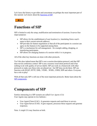
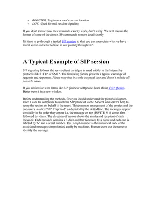
![(INVITE+OK+ACK) is used for reliable call setup. Note that the ACK message is not
using the proxies to reach user2 as by now user1 knows the exact location of user2.
Once the connection has been setup, media flows between the two endpoints. Media flow
is controlled using protocols different from SIP e.g. RTP.
When one party in the session decides to disconnect, it (user2 in this case) sends a BYE
message to the other party. The other party sends a 200 OK message to confirm the
termination of the session.
Was that a bit long? Need a break? Go, get it! You deserve a break after going through
such a long SIP session -:) When you get back, we will dive inside a SIP request
message.
Request Message Format of SIP
Back already! Well, let's continue.
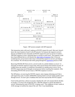
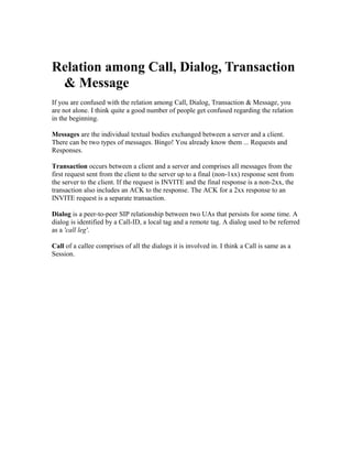
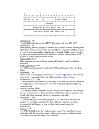
In the previous SIP session example we have seen that requests are sent by clients to
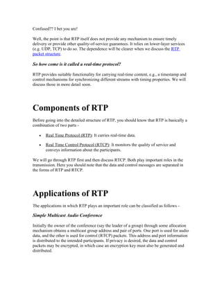
servers. We will now discuss what that request actually contains. The following is the
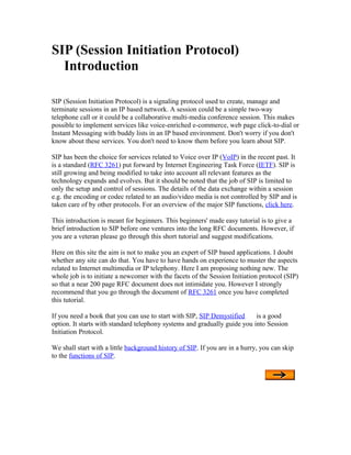
format of INVITE request as sent by user1.
INVITE sip:user2@server2.com SIP/2.0
Via: SIP/2.0/UDP pc33.server1.com;branch=z9hG4bK776asdhds Max-Forwards: 70
To: user2 <sip:user2@server2.com>
From: user1 <sip:user1@server1.com>;tag=1928301774
Call-ID: a84b4c76e66710@pc33.server1.com
CSeq: 314159 INVITE
Contact: <sip:user1@pc33.server1.com>
Content-Type: application/sdp
Content-Length: 142
---- User1 Message Body Not Shown ----
The first line of the text-encoded message is called Request-Line. It identifies that the
message is a request.
Request-Line
Method SP Request-URI SP SIP-Version CRLF
[SP = single-space & CRLF=Carriage Return + Line Feed (i.e. the character inserted when you press the
"Enter" or "Return" key of your computer)]
Here method is INVITE, request-uri is "user2@server2.com" and SIP version is 2.
The following lines are a set of header fields.
• Via:](https://image.slidesharecdn.com/sip-120904055850-phpapp01/85/Sip-7-320.jpg)
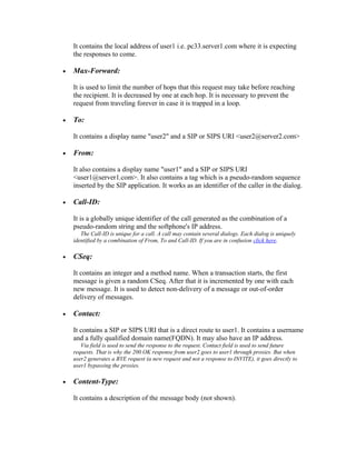
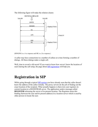
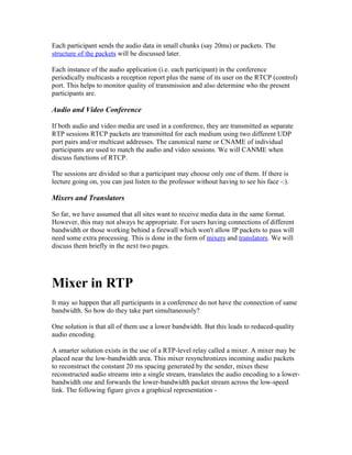
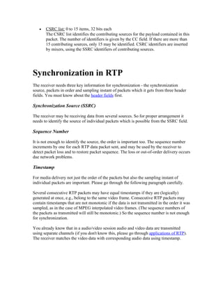
![• Content-Length:
It is an octet (byte) count of the message body.
The header may contain other header fields also. However those fields are optional.
Please note that the body of the message is not shown here. The body is used to convey
information about the media session written in Session Description Protocol (SDP). You
may continue your journey through SIP without worrying about SDP right now. However
it doesn't hurt to take a peep.
Your SIP request is waiting to get a SIP response message.
Response Message Format of SIP
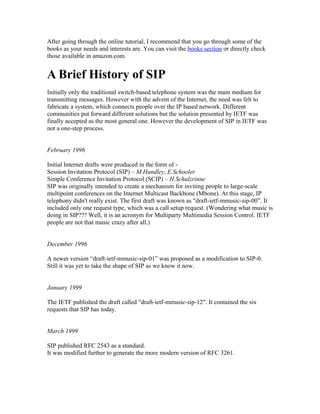
Here is what the SIP response of user2 will look like.
SIP/2.0 200 OK
Via: SIP/2.0/UDP site4.server2.com;branch=z9hG4bKnashds8;received=192.0.2.3
Via: SIP/2.0/UDP
site3.server1.com;branch=z9hG4bK77ef4c2312983.1;received=192.0.2.2
Via: SIP/2.0/UDP pc33.server1.com;branch=z9hG4bK776asdhds;received=192.0.2.1
To: user2 <sip:user2@server2.com>;tag=a6c85cf
From: user1 <sip:user1@server1.com>;tag=1928301774
Call-ID: a84b4c76e66710@pc33.server1.com
CSeq: 314159 INVITE
Contact: <sip:user2@192.0.2.4>
Content-Type: application/sdp
Content-Length: 131
---- User2 Message Body Not Shown ----
Status Line
The first line in a response is called Status line.
SIP-Version SP Status-Code SP Reason-Phrase CRLF
[SP = single-space & CRLF=Carriage Return + Line Feed (i.e. the character inserted when you press the
"Enter" or "Return" key of your computer)]
Here SIP version is 2, Status-Code is 200 and Reason Phrase is OK.
The header fields that follow the status line are similar to those in a request. I will just
mention the differences
• Via:](https://image.slidesharecdn.com/sip-120904055850-phpapp01/85/Sip-9-320.jpg)

SIP is a signaling protocol used to create, manage, and terminate multimedia sessions over IP networks. It allows for establishing the location of users, negotiating features between participants in a session, and managing calls by adding, dropping or transferring participants. SIP is responsible for setting up sessions but not for transmitting media or controlling quality of service - those functions are handled by other protocols. A typical SIP call involves a SIP client sending an INVITE request which is forwarded through SIP proxies to the destination, where if accepted, a 200 OK response confirms call setup along with an ACK from the initiator.


![1 VoIP Overview[1]](https://cdn.slidesharecdn.com/ss_thumbnails/1voipoverview1-12499217322207-phpapp02-thumbnail.jpg?width=640&height=640&fit=bounds)


