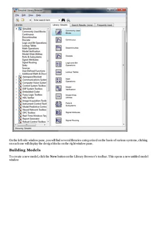
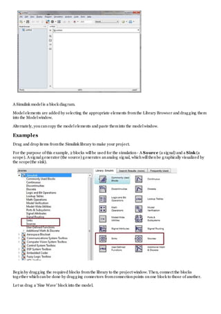
http://www.tutorialspoint.com/matlab/matlab_simulink.htm Copyright © tutorialspoint.com
MATLAB - SIMULINK
Simulink is a simulationand model-based designenvironment for dynamic and embedded systems, integrated
withMATLAB. Simulink, also developed by MathWorks, is a data flow graphicalprogramming language toolfor
modeling, simulating and analyzing multi-domaindynamic systems. It is basically a graphicalblock diagramming
toolwithcustomizable set of block libraries.
It allows youto incorporate MATLAB algorithms into models as wellas export the simulationresults into
MATLAB for further analysis.
Simulink supports:
system-leveldesign
simulation
automatic code generation
testing and verificationof embedded systems
There are severalother add-onproducts provided by MathWorks and third-party hardware and software
products that are available for use withSimulink.
The following list gives brief descriptionof some of them:
Stateflow allows developing state machines and flow charts.
Simulink Coder allows to automatically generate C source code for real-time implementationof
systems.
xPC Target together withx86-based real-time systems provides anenvironment to simulate and
test Simulink and Stateflow models inreal-time onthe physicalsystem.
Embedded Coder supports specific embedded targets.
HDL Coder allows to automatically generate synthesizable VHDL and Verilog
SimEvents provides a library of graphicalbuilding blocks for modeling queuing systems
Simulink is capable of systematic verificationand validationof models throughmodeling style checking,
requirements traceability and modelcoverage analysis.
Simulink DesignVerifier allows youidentify designerrors and generates test case scenarios for model
checking.
Using Simulink
To openSimulink, type inthe MATLAB work space:
simulink
Simulink opens withthe Library Browser. The Library Browser is used for building simulationmodels.
Onthe left side window pane, youwillfind severallibraries categorized onthe basis of various systems, clicking
oneachone willdisplay the designblocks onthe right window pane.
Building Models
To create a new model, click the New buttononthe Library Browser's toolbar. This opens a new untitled model
window
A Simulink modelis a block diagram.
Modelelements are added by selecting the appropriate elements fromthe Library Browser and dragging them
into the Modelwindow.
Alternately, youcancopy the modelelements and paste theminto the modelwindow.
Examples
Drag and drop items fromthe Simulink library to make your project.
For the purpose of this example, 2 blocks willbe used for the simulation- A Source (a signal) and a Sink (a
scope). A signalgenerator (the source) generates ananalog signal, whichwillthenbe graphically visualized by
the scope(the sink).
Beginby dragging the required blocks fromthe library to the project window. Then, connect the blocks
together whichcanbe done by dragging connectors fromconnectionpoints onone block to those of another.
Let us drag a 'Sine Wave' block into the model.
Select 'Sinks' fromthe library and drag a 'Scope' block into the model.
Drag a signalline fromthe output of the Sine Wave block to the input of the Scope block.
Runthe simulationby pressing the 'Run' button, keeping allparameters default (youcanchange themfromthe
Simulationmenu)
Youshould get the below graphfromthe scope.

Matlab simulink

  • 1.
    http://www.tutorialspoint.com/matlab/matlab_simulink.htm Copyright ©tutorialspoint.com MATLAB - SIMULINK Simulink is a simulationand model-based designenvironment for dynamic and embedded systems, integrated withMATLAB. Simulink, also developed by MathWorks, is a data flow graphicalprogramming language toolfor modeling, simulating and analyzing multi-domaindynamic systems. It is basically a graphicalblock diagramming toolwithcustomizable set of block libraries. It allows youto incorporate MATLAB algorithms into models as wellas export the simulationresults into MATLAB for further analysis. Simulink supports: system-leveldesign simulation automatic code generation testing and verificationof embedded systems There are severalother add-onproducts provided by MathWorks and third-party hardware and software products that are available for use withSimulink. The following list gives brief descriptionof some of them: Stateflow allows developing state machines and flow charts. Simulink Coder allows to automatically generate C source code for real-time implementationof systems. xPC Target together withx86-based real-time systems provides anenvironment to simulate and test Simulink and Stateflow models inreal-time onthe physicalsystem. Embedded Coder supports specific embedded targets. HDL Coder allows to automatically generate synthesizable VHDL and Verilog SimEvents provides a library of graphicalbuilding blocks for modeling queuing systems Simulink is capable of systematic verificationand validationof models throughmodeling style checking, requirements traceability and modelcoverage analysis. Simulink DesignVerifier allows youidentify designerrors and generates test case scenarios for model checking. Using Simulink To openSimulink, type inthe MATLAB work space: simulink Simulink opens withthe Library Browser. The Library Browser is used for building simulationmodels.
  • 2.
    Onthe left sidewindow pane, youwillfind severallibraries categorized onthe basis of various systems, clicking oneachone willdisplay the designblocks onthe right window pane. Building Models To create a new model, click the New buttononthe Library Browser's toolbar. This opens a new untitled model window
  • 3.
    A Simulink modelisa block diagram. Modelelements are added by selecting the appropriate elements fromthe Library Browser and dragging them into the Modelwindow. Alternately, youcancopy the modelelements and paste theminto the modelwindow. Examples Drag and drop items fromthe Simulink library to make your project. For the purpose of this example, 2 blocks willbe used for the simulation- A Source (a signal) and a Sink (a scope). A signalgenerator (the source) generates ananalog signal, whichwillthenbe graphically visualized by the scope(the sink). Beginby dragging the required blocks fromthe library to the project window. Then, connect the blocks together whichcanbe done by dragging connectors fromconnectionpoints onone block to those of another. Let us drag a 'Sine Wave' block into the model.
  • 4.
    Select 'Sinks' fromthelibrary and drag a 'Scope' block into the model. Drag a signalline fromthe output of the Sine Wave block to the input of the Scope block.
  • 5.
    Runthe simulationby pressingthe 'Run' button, keeping allparameters default (youcanchange themfromthe Simulationmenu) Youshould get the below graphfromthe scope.