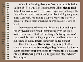
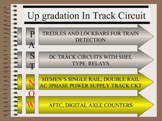
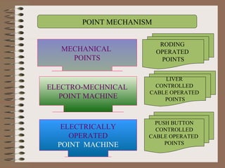
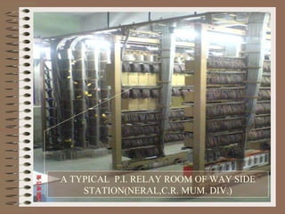
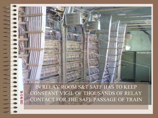
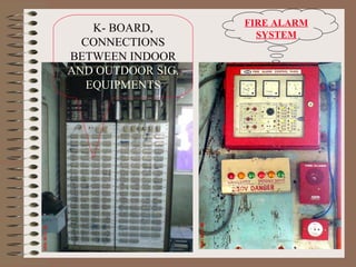
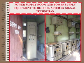
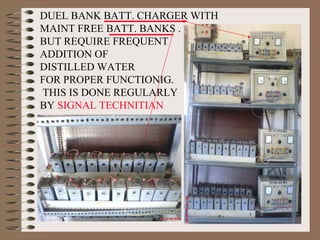
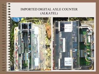
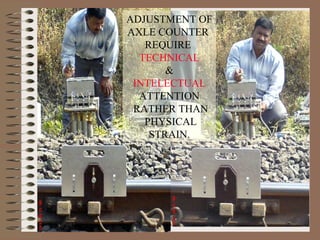
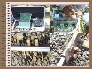
This document outlines the components, working, and applications of track circuits used in rail signaling. Track circuits use batteries, track relays, and adjustable resistances to detect train occupancy through changes in electrical current flow. Insulated rail joints are also used to isolate adjacent track circuits. When unoccupied, current flows through the track relay keeping it energized, but when a train is present its wheels shunt most of the current, causing the relay to deactivate. Track circuits allow signals to display red only when a track segment ahead is occupied by a train.
The document discusses different types of Automatic Track Circuit (AFTC) technologies including ABB (TI-21), Siemens (FTGS), and Alstom. It provides technical specifications, components, block diagrams, and advantages of these AFTC systems. The key information covered includes operating frequencies and modulation methods, maximum effective track circuit lengths, indoor and outdoor equipment used, and track connections/separation joints.
This Simple-cost effective-easy to maintain track circuit can be used to identify an incoming train so that it can automatically trigger an alarm system as well as the railway gate. This system is assured to be fail-safe.
Signalling in railways involves conveying information to loco drivers through visual or audible signals to control train movement. There are two main signalling systems - time interval and space interval. Space interval method divides tracks into blocks and uses fixed signals like semaphore or colour light signals to indicate if a block is occupied or clear. Solid state interlocking (SSI) systems have replaced older relay-based interlocking to reduce costs and improve maintainability through use of electronic components instead of relays.
This document provides a preface and contents for the book "Indian Railway Signal Engineering Volume-IV" by Pramod P. Goel. The preface gives background on the author and his motivation for writing the book. It explains that the book covers the electrical portion of signal and interlocking systems in India and is divided into nine chapters. The contents section lists these nine chapters which cover topics like electrical signalling systems, operating devices, operated equipment, transmission cables, and electrical interlocking using relays. It provides high-level descriptions of what will be discussed in each chapter.
The document provides an overview of various topics related to railway signaling and communication systems used in the Kota division of Indian Railways. It discusses the role of the Divisional Railway Manager and describes four branches under DRM Kota. It then summarizes signaling systems including semaphore and color light signals. Other topics covered in brief include track circuits, points, data loggers, microwave communication, optical fiber communication, and their applications in railways.
The Saudi Railways Organisation awarded a contract to Siemens and Nour Communications to improve safety and increase capacity on the Dammam to Riyadh rail line. The project included installing an ETCS signaling system, GSM-R communications, and a new control center to monitor train movements. Nour Communications was responsible for civil works, power systems, installation, and 5 years of maintenance support.
Interlocking is a system that coordinates railway signals and switches (points) to prevent unsafe situations like train collisions. Mechanically operated interlocking schemes connect levers controlling signals and switches so their positions are literally "interlocked," preventing conflicting operations like allowing two trains on the same section of track. For instance, obtaining a key for a route's switches prevents clearing another conflicting route. Interlocking coordinates signal box or cabin control of a region to ensure safe train movements.
The document discusses railway communication systems in India. It describes the layout and control of the Eastern Railways, the types of signals used, and communication technologies like MTRC, walkie talkies, voice loggers, and emergency portable control telephones. It also outlines the basic features of GSM-R communication and types of control systems. Various communication mediums are presented, including overhead, underground, microwave, and optical fiber systems.
This presentation summarizes the Indian railway signal system. It introduces the Indian railway network as the 4th largest in the world comprising over 115,000 km of track. It then describes the key components of the railway signaling system including block signals, fixed signals, mechanical signals, color light signals and cab signals. It also discusses interlocking systems which use mechanical and electrical devices to coordinate signaling and ensure safe train movements. The presentation concludes by covering communication systems used for train traffic control such as microwave transmission and optical fiber communication.
Railway Engineering: signaling, interlocking, train control systemBathla Tuition Centre
This Presentation Contains Railway engineering concepts. The contents covered are Railway Signaling, Interlocking & trail control system.
Feel free to write in Comment Section or drop a line in my Inbox amanbathla710@gmail.com
innovative railway track surveying with sensors and controlled by wireless co...kalaimathi mathiyazhagan
This document describes a proposed multi-sensor railway track geometry surveying system. The system uses MEMS, ultrasonic, and GPS sensors on a robot to detect cracks and obstacles on railway tracks and bridges in real-time. When issues are detected, the GPS location is recorded and an SMS is sent to authorities via GSM. Trains approaching will also receive a wireless message to slow down. A microcontroller controls gate closures to prevent accidents. The low-cost system aims to improve safety by allowing for faster response times over existing manual inspection methods.
Signaling systems in railways convey information to train drivers regarding train movements. The two main types are time interval and space interval methods. The space interval method divides tracks into blocks and only allows one train per block, ensuring space between trains. It uses visual signals like semaphore arms and color light signals, as well as audible signals. Track circuits, points, and slots are also key signaling elements that detect train presence and enable route setting and dual control of infrastructure. The goal of signaling is to safely dispatch and receive trains at stations by controlling train movements between stations through block systems.
The document discusses railway signaling and transportation. It describes the need for railway signaling to safely manage train traffic, given that trains travel quickly on fixed tracks and have limited ability to stop. It then covers types of signals like color light and semaphore signals. The document also provides a brief history of railway signaling development from early mechanical systems to current electronic and computer-controlled technologies. It concludes with discussions of microprocessor-based signaling systems, redundancy features, and concepts like centralized traffic control and potential future automated train control.
This PPT is very useful for the beginners interested for Metro Railway signalling system. It covers an overview of Signalling from fixed block to CBTC moving block system. It also includes the importance of CBTC over fixed block.
Communication Based Train Control (Mobile Train Radio Communication)Suraj Talreja
This document provides an overview of Mobile Train Radio Communication (MTRC) systems. It discusses how MTRC systems allow trains to continuously communicate their exact position, speed, and direction to trackside equipment to safely manage train traffic and spacing. The document outlines the typical components, architecture, benefits, and risks of MTRC systems. It also provides examples of MTRC system projects in India and discusses the initial implementation and challenges of early MTRC systems in India.
The document discusses various aspects of signalling systems used in Indian metro rail networks such as Kolkata Metro, Delhi Metro, and Bangalore Metro. It describes signalling equipment like point machines, track circuits, and different types of signals including cab signals, fixed signals, and flag signals. The document also provides information on interlocking, train control systems, and operation control centres used for train movement and safety.
Signal and telicommunication/sanjeet-1308143sanjeet kumar
This document provides information about Sanjeet Kumar's 6 week industrial training at the East Central Railway Hajipur HQ Signal & Telecommunication department. It includes summaries of optical fiber communications, telephone exchanges, STM-1, mobile communications, video conferencing, and the basic components and history of railway signaling and control systems in India such as interlocking, panel interlocking, route relay interlocking, and track circuits.
The document provides maintenance information for the Eldyne AzLS single section digital axle counter system. It details procedures for fixing track devices after rail replacement, adjusting rail contact transmit heads using a dummy wheel and test equipment, and resetting the system. Key steps include drilling mounting holes for rail contacts in the correct position, using a test kit to measure signal levels and adjust potentiometers to equalize rectified and reference voltages, and operating the reset box to initiate a reset. Proper maintenance following the guidance helps ensure trouble-free performance of the digital axle counter.
Signalling systems are used to safely and efficiently control train movements on tracks. The main purposes of signalling are to provide for safe train operations, maximize track usage, and maintain safety for passengers, staff and trains. Early signalling in the 1820s-1830s involved uniformed men guiding trains by hand or flags. Signals are classified by their operating characteristics, functions, locations, and special purposes. Operating characteristics include hand, fixed, and detonating signals. Functional signals include stop/semaphore, warner, and shunting signals. Signalling has evolved from manual methods to include fixed, colour light, and other automated signals to safely direct train operations.
This document discusses safety concepts and practices in railway signalling. It covers fail-safe principles, redundancy techniques, and self-check methods used to ensure safety in signalling systems. The key points are:
1) Signalling systems are designed to be fail-safe, meaning any failure will result in a safe reaction by defaulting to the lowest energy state. This is achieved through mechanical and electrical designs.
2) Microprocessors are not inherently fail-safe, so redundancy and self-checks are used to monitor for faults and ensure safe operation. Techniques include dual hardware, triple modular redundancy, and watchdog timers.
3) Railway interlocking systems are designed so that running signals cannot be lowered unless routes are set
This document discusses railway signaling systems. It describes that signaling conveys information from station masters to loco drivers about stopping, proceeding with caution, or continuing. There are two main types of signaling systems - time interval and space interval. The time interval method spaces trains over a track based on braking distances, but it cannot handle high traffic volumes. The space interval (block) method divides tracks into sections and only allows one train in a section at a time through the use of visual and audible signals like semaphore arms, color lights, flags, and whistles. Within the space interval method, semaphore signaling uses rotating arms at different angles while color light signaling uses consistent day/night aspects and has advantages
The document discusses railway signalling systems. It describes how signals are used to safely regulate train movements and maximize track utilization. Early systems used policemen and hand signals, while modern signalling was introduced in England in 1842 using fixed semaphore signals and detonators. Signals communicate different instructions like stop, caution, or proceed using aspects like colored lights, positions of arms, or detonator explosions. The classification, types, and locations of various signals are also outlined.
Unmanned railway tracking and anti collision system using gsmvmohankumar5
This document describes an anti-collision system for unmanned railway crossings that uses GPS receivers in trains to track locations and prevent collisions. When trains get within a minimum distance, both will stop. Infrared sensors activate gate controls when a train reaches a specific spot. Train locations are sent via GSM modem to a server and displayed to alert drivers. The system uses a microcontroller, sensors, transmitters, receivers and other hardware to monitor trains and control gates for increased safety.
This ppt describes the types of signals used in Indian railway and other railways around the world. They may seem complicated but their applications are fascinating, espesially you will like signals such as detonators which blast (certainly not harmful but they warn the drivers by their blast)
This document proposes a method for generating electricity from wind induced by moving vehicles like trains. The system would involve installing wind turbines on trains that would capture the high-pressure wind created as the train moves. As the turbines spin, a generator would convert the kinetic energy of the wind into electrical energy. This presents a renewable energy solution that could harness wind power from trains continuously throughout the year. The document outlines the objectives, introduction, energy requirements, background, method, basic diagram, model, working principle, advantages, limitations, applications, cost economics and conclusion of the proposed train-mounted wind turbine system.
Wind Energy Conversion System Using PMSG with T-Source Three Phase Matrix Con...IJTET Journal
This document presents a wind energy conversion system using a permanent magnet synchronous generator (PMSG) connected to a T-source three-phase matrix converter. The system aims to efficiently harness wind power and deliver it to a load. A PMSG is connected to a three-phase diode rectifier and input capacitors, with the output fed to a T-source network and three-phase matrix converter. The converter can boost output voltage regardless of input voltage and regulate it through shoot-through control. MATLAB/Simulink models are developed and simulations show the converter produces controlled output voltage and current waveforms to power the load efficiently with fewer components than traditional converter topologies.
The document proposes installing mini wind turbines on train coaches to generate electricity. It describes how wind energy is captured via wind turbine blades and converted to electrical energy through a generator. By placing vertical-axis wind turbines on train roofs, it is estimated that 1.515 kW of power could be generated per coach using lightweight aluminum blades, a small generator, stainless steel shaft, lightweight gears, and batteries to store the power. The innovative system would help minimize energy crises by harnessing the energy from moving trains.
Two industrial designers from China and Italy developed a device called the T-box that can generate power from wind energy. The T-box utilizes a unique form of wind power through a design that is efficient to install and maintain. It requires less space than traditional wind farms and can help supplement wind power generation around the world.
This document presents a design for generating electricity from railway tracks. It introduces the concept of converting rotational energy from trains passing over tracks into electrical energy. The objectives are to use dynamos connected to the tracks to generate a voltage that can be used to charge lead-acid batteries. Some advantages are that a high electrical output can be achieved by increasing the gear ratio between the tracks and generators. The generated power could be used for applications like charging mobile phones and powering displays, lights, and equipment at train stations. It suggests implementing this system at entry and exit points of busy railway stations.
This document proposes generating electricity from wind turbines mounted on fast moving vehicles like trains. It describes different turbine designs that could be fitted to trains, including J-shaped turbines, and how they would capture and compress wind to drive generators. The turbines could power train compartments or batteries and excess power could be fed back into the electric grid. Mounting turbines on India's large fleet of trains could generate a substantial amount of renewable energy each year.
The document proposes a system to generate electricity from railway tracks. It uses a generator powered by a variable capacitor that is primed by a power source. As trains pass over the tracks, the changing capacitance extracts significant electrical energy. Circuit diagrams show components like a reservoir, power tie line, motor, generator and processor that condition the power and control generation. Mathematical calculations demonstrate how capacitance and electrical potential vary based on factors like dielectric thickness and plate distance. The conclusion states that this approach economically produces sufficient power by increasing the capacitor's electrical energy by 2400 times through movements on the rail system.
power generation from railway track in an advanced technology by which the power can be generated with help of motion of the rail and can be stored in the form of generators or can reuse.
This document describes a project to generate electricity from railway tracks. A train model with a magnet passes over coils attached to the tracks, inducing voltage in the coils. This alternating current is rectified and stored in a battery. A charge controller protects the battery from overcharging. An inverter converts the direct current to alternating current that can power devices. The project aims to help address electricity shortages by generating power from passing trains without fuel inputs.
Satellite communication uses satellites as relay stations to transmit radio and television signals between Earth stations. There are over 750 communication satellites currently in orbit. They provide wide area coverage, transmission regardless of distance, and a transmission delay of about 0.3 seconds. Common types are fixed satellites for point-to-point communication, broadcast satellites for television/radio, and mobile satellites for satellite phones. Satellites can be in low, medium or geostationary orbits depending on their purpose and coverage needs. Frequency bands like C-band, Ku-band and Ka-band are used depending on the satellite type and application.
This document discusses railway signaling and communication systems in India. It provides background on Indian Railways, the largest commercial employer in the world. It then describes different types of railway signaling such as block signaling and color light signaling used to safely direct train traffic. Interlocking systems using mechanical and electrical devices are also discussed to prevent conflicting train movements. The document concludes by covering various wired and wireless communication systems used by Indian Railways including microwave transmission, overhead lines, and optical fiber networks.
hiee guyes this is swapnil thaware here i uploaded slide for your knowledge if you want more detail msg me on fb or mail i will help you
thanking you and slideshare.com
This document provides an overview of basic telecommunication concepts. It defines telecommunication as the transmission of information that allows communication over distance. Examples of telecommunication systems include telephone, satellite, mobile cellular, radar/sonar, and microwave radio. The key components of a telecommunication system are a transmitter that converts a message into a signal, a transmission medium that carries the signal, and a receiver that converts the signal back into usable information.
Édouard Estaunié coined the term "télécommunication" in 1904 from the Greek prefix "tele-" meaning "far off" and the Latin word "communicare" meaning "to share". The first commercial electrical telegraph was constructed in 1839 and the first commercial telephone services began in the late 1870s. Today, Bharti Airtel is India's largest telecommunications company with over 300 million subscribers across its mobile, fixed line, high speed broadband and DTH services. Airtel continues to invest heavily in expanding its network across India with a goal of covering 95% of the population by 2010.
A solar tree is a decorative means of producing solar energy and also electricity. It uses multiple no of solar panels which forms the shape of a tree. The panels are arranged in a tree fashion in a tall tower/pole.
TREE stands for
T= TREE GENERATING
R=RENEWABLE
E=ENERGY and
E=ELECTRICITY
This is like a tree in structure and the panels are like leaves of the tree which produces energy.
This document summarizes a presentation about satellite communication. It discusses the basic concept of a communication satellite, how satellites are used as relay stations to transmit signals between Earth stations, and the different types of satellite orbits including geostationary, low Earth, and medium Earth orbits. It also covers topics like inter-satellite links, routing between satellites, common modulation techniques, and recent developments in satellite communication technology.
This document provides an overview of measurement and relay indications. It begins with an introduction and then discusses the functions of protection schemes, which are to sense faults, operate circuit breakers to isolate faulty equipment, and clear faults before systems become unstable. It also classifies protective relays based on technology into electromechanical, solid state, and digital/numerical relays. It describes examples and characteristics of each type. The document further discusses ANSI standard device numbers, and then describes various measuring instruments like ammeters, voltmeters, wattmeters, power factor meters, and frequency meters. It provides details on their construction, working principles, and types.
The document discusses the operation of power systems and control centers. It provides background on how electricity is generated and transmitted on a large scale to power grids. Control centers use SCADA systems and digital computers to monitor the entire power system in real time, control generation and transmission equipment, and ensure reliable and economic operation of the grid. Key functions of control centers include automatic generation control, economic dispatch, system security, and load forecasting. Critical data is acquired from sensors every 2 seconds to track the state of the power system.
Design of embedded based three phase preventor and selector system for indust...IAEME Publication
This document summarizes a research paper that presents the design of an embedded-based three-phase preventor and selector system for industrial appliances. The system uses a microcontroller to control MOSFET-based inverters and provide safety operations for industry applications. It protects appliances from damage if one phase fails by using the power from another available phase. The system includes components like a DIP switch, microcontroller, signal amplifier, inverter circuitry, opto-isolator, gate drive power supply and MOSFET-based inverter to selectively provide power from one of three phases to industrial equipment.
Electrical Technology was founded on the remarkable discovery by Faraday that a changing magnetic flux creates an electric field. Out of that discovery, grew the largest and most complex engineering achievement of man : the electric power system. Indeed, life without electricity is now unimaginable. Electric power systems form the basic infrastructure of a country. Even as we read this, electrical energy is being produced at rates in excess of hundreds of giga-watts (1 GW = 1,000,000,000 W). Giant rotors spinning at speeds up to 3000 rotations per minute bring us the energy stored in the potential energy of water, or in fossil fuels. Yet we notice electricity only when the lights go out!
While the basic features of the electrical power system have remained practically unchanged in the past century, but there are some significant milestones in the evolution of electrical power systems.
This document describes a transmission line fault detector robot that will automatically move along transmission lines and detect discontinuities. It will use an electromagnetic induction sensor near the line to detect faults when voltage is not present. The robot is microcontroller-based and will indicate faults to the operator via an LCD screen. It will test lines by changing the phase on each wire individually to identify faulty cables.
This document is a project report on a microcontroller based traffic light controller. It describes the development of a traffic light controller that uses a microcontroller and LEDs to automatically control traffic lights on a centralized basis. The microcontroller is programmed to adjust the timing and phasing of the traffic signals to meet changing traffic conditions. The circuit uses basic electronic components like an LED for the traffic lights and a microcontroller for automatic signal changing after a preset time interval. It aims to provide a reliable and cost-effective traffic light control solution.
A DAPTIVE S UPPLY V OLTAGE M ANAGEMENT F OR L OW P OWER L OGIC C IRCU...VLSICS Design
With the rise in demand of portable hand held devic
es and with the rise in application of wireless sen
sor
networks and RFID reduction of total power consumpt
ion has become a necessity. To save power we
operate the logic circuitry of our devices at sub-t
hreshold. In sub-threshold the drain current is
exponentially dependent on the threshold voltage he
nce the threshold variation causes profound variati
on
of I
ON
and I
OFF
the ratio of which affect the speed of a circuit d
rastically. So to mitigate this problem we
present a adaptive power management circuit which w
ill determine the minimum required supply voltage
to meet the timing requirement. Also to reduce the
power overhead and avoid bulky coil and EMI noise
we used the switch capacitor power regulator to reg
ulate and manage power instead of linear dropout
(LDO) and Inductor base switch mode power converter
This project aims to implement sensorless speed detection of induction motors using fluctuations in the zero crossings of the three-phase motor current. Current transformers are used to sense the motor current, and a microcontroller analyzes the zero crossing times to determine motor speed without the need for sensors. The current signals are buffered using voltage followers before being input to the microcontroller. Fast Fourier transform algorithms are then used to detect the motor speed based on fluctuations in the current zero crossings. This sensorless method provides a low-cost solution for speed measurement in applications where sensors cannot be used.
HIOKI’s Next Generation Automotive Measurement Solutions
Fast Charging Stations
Power Conversion of Power Systems
Energy Consumption Assessment Tests
Compliance Testing of Batteries
Test High-voltage Battery Packs
Automotive Electronics
Record ECU Signals
Test Electrical Characteristics of Auto Parts
Essential Tools for On-site Maintenance
Wireless Power Transmission Evaluation System
https://www.n-denkei.com/singapore/inquiry/
This document is a summer training report submitted by Anuj Bansal describing their training at the 400kV substation in Mottiram Adda, Gorakhpur, Uttar Pradesh. The report provides details about the electrical equipment at the substation including transformers, cooling fans, circuit breakers, isolators, lightning arresters, relays, capacitor voltage transformers, current transformers, the battery room, control room, and single line diagram. It also lists references used in preparing the report.
This document summarizes a student project report on developing a microcontroller-based traffic light controller. It describes using an AT89C51 microcontroller programmed to control LED traffic lights through four phases to regulate traffic flow at an intersection. The circuit diagram and hardware components are explained, including a power supply, microcontroller, LEDs, 7-segment display, and common cathode configuration. Software and timing of the four light phases are also outlined to coordinate traffic flow from four directions through the intersection.
The document describes a closed loop speed control scheme for a BLDC motor using a Zeta converter. It aims to design a controller that allows the motor to rotate at a desired speed and direction. The proposed system uses a Zeta converter for DC bus voltage control and internal inverter control, eliminating the need for external components. It also enables closed loop speed control using a PI controller for error minimization between actual and desired speeds. The system was simulated in MATLAB Simulink and a hardware prototype was developed and tested demonstrating speed control capability.
An inverter is an electronic device that converts direct current (DC) to alternating current (AC). It allows appliances designed to run on AC power to operate using a DC power source. There are different types of inverters that produce either a square wave or sine wave output. Modern inverters use electronic components like inductors and capacitors to gradually switch the current direction and produce a smoother sine wave output similar to standard utility AC power. Inverters are useful for powering AC devices from batteries or solar panels that produce DC electricity. They are commonly used in electric vehicles, backup power systems, and off-grid homes that use renewable energy.
SOLAR POWERED WIRELESS CHARGING STATION FOR ELECTRIC CYCLEIRJET Journal
This document describes the design of a solar powered wireless charging station for electric bicycles. The charging station uses inductive coupling between transmitting and receiving coils to wirelessly charge electric bicycles. An RFID system reads tags on bicycles to allow authorized users to charge and block unauthorized users. The charging level, user records, and vehicle directions are monitored and controlled through a mobile application. The goal is to create an affordable, portable, and user-friendly wireless charging solution for electric bicycles that reduces infrastructure costs and the need for wires.
IRJET-Analysis and Rectification of Fault in Power System by Multilevel Modul...IRJET Journal
This document discusses modular multilevel converters (MMC) and their use in high voltage direct current (HVDC) power transmission systems. Key points:
- MMC topology offers advantages over traditional voltage source converters for HVDC, including higher voltage capability, modularity, improved reliability, and reduced filters/complexity.
- MMC works by connecting sub-modules containing switching elements in series. Controlling the number of inserted/bypassed sub-modules produces a stepped output voltage.
- Simulation results show the MMC can successfully control output power and maintain stable operation even during faults, by decoupling energy and current control loops through saturation limits.
Automatic Power Factor Corrector Using Arduino reportSelf-employed
This document describes an automatic power factor corrector system using an Arduino microcontroller. The system measures the power factor of a load by determining the phase difference between the line voltage and current signals. It then calculates the required compensation and switches capacitors from a capacitor bank to normalize the power factor close to unity. This improves the efficiency of the power system by reducing losses. The automatic correction allows for varying loads by adjusting the capacitors proportionately.
The article is devoted to the study and introduction of modern technologies in electro-technical branch of the industry for the purpose of increasing reliability of electric supply. Appling the latest technical developments marketed in automatic breakers Compact NS and Master pact of the company "Schneider Electric", for modernization distributing device 0,4 kV applied transformer substation is offered in it. Zhalilov Rashid"The Intellectual Automated Substation" Published in International Journal of Trend in Scientific Research and Development (ijtsrd), ISSN: 2456-6470, Volume-2 | Issue-3 , April 2018, URL: http://www.ijtsrd.com/papers/ijtsrd11597.pdf http://www.ijtsrd.com/engineering/electrical-engineering/11597/the-intellectual-automated-substation/zhalilov-rashid
This paper proposes a single-bit ADC system based Proportional and Integral (PI) controller to maintain a desired level of power transfer efficiency in Capacitive Power Transfer (CPT) systems. In this paper, a simple single-bit ADC system i.e., Single-Bit Modulator (SBM) is considered as an alternative to the commonly used multi-bit ADC systems. Unique features of employing SBM are 1) its ability to convert analog signals into single-bit signals and 2) its easy integrability in digital chips with linear variable differential transformers (LVDTs) such as FPGAs. A SBM based PI (SBM-PI) controller is designed to judicially interface with the single-bit output of SBM. The proposed (SBM-PI) controller guarantees less hardware resources, latency and regulates the output voltage to provide the desired power transfer efficiency. The behavior of SBM-PI controller is compared to that of a conventional multi-bit controller, with the results of both controllers being identical. The effectiveness of the proposed controller with SBM is further demonstrated using the experimental prototype of CPT by implementing a SBM-PI controller using $16$ MHz ATmega8 microcontroller. The experimental results from a laboratory prototype illustrate that SBM-PI controller successfully regulates the output voltage of CPT to control the power flow.
The document discusses the design and components of electrical power grids. It begins with an introduction to power grids, noting their three main components: power stations, transmission lines, and transformers. It then covers various topics related to designing a power grid substation including selecting the site, layout designs, busbar schemes, safety clearances, earth mat design, and control rooms. Key equipment for grids are also discussed such as lighting arrestors, current and potential transformers, circuit breakers, and isolators. The presentation concludes that grids are important for supplying reliable and economic power from sources to loads and maintaining efficiency, though their design and components make them costly.
2. When Interlocking first was first introduced in India during 1879 it was first Indirect type using Mechanical Key. This was followed by Direct Type Interlocking with Lever Frame which are actually mechanical logical gates . They were vary robust and a typical way side station will consist of these gates weighing approximately 5 tons of steel. Development of electrical Relay and Power Supply has evolved a relay based Interlocking over the years. With the advent of fail safe technique ‘ microprocessor’ were used for Interlocking application and has proved as a substitute to Relay Interlocking with added benefit . Thus the purely Mechanical Signaling of 50’s slowly made way to Power Signaling followed by Route Relay Interlocking and Panel Interlocking . Latest Solid State Interlocking with Data loggers and other advance Techniques.
3. The technical up gradation in the Signaling System is not limited to a particular section and are more rapid within these 10 to 15 years. The Evaluation of the sealed maintenance free Batteries (VRLA) are replacing Lead Acid Cells.Introduction of Integrated Power Supply (IPS), Uninterrupted Power Supply (UPS) with the help of VRLA Batt., supports Signaling Systems to face power Supply Crises vary effectively. On the Telecommunication front it saw the emergence of Electronic Exchanges from the manual types.T43 Trunk board giving way to EPBAX. Overhead alignment of Optic fiber System . 17 Impulses way station equipment to vary powerful Solid State Control Communication Equipment . From simple walkie talkie sets to mobile communication and analogue microwave by Digital Microwave equipment .
4.
5. INTERLOCKING EARLY 50’S DIRECT TYPE INTERLOCKING ( LEAVER FRAME ,LOGIC GATES-ROBUST AND CONTAINS MINIMUM OF 3 TONES OF STEEL ) ELECTRO MECHANICAL INTERLOCKINGS LEAVER LOCK, CKT. CONTROLLER, REVERCERS AT PRESENT` Purely Electrical Interlocking RRI, PI NEXT FUTURE SOLID STATE INTERLOCKING
6. NOW AND FUTURE 1N 50’S IN 90’S Up gradation In Signal SEMAPHORE ARM SIGNALING , DOUBLE WIRE MECHANISM, REVERSERS, MECH.CRANKS COLOUR LIGHT SIGNALING, DOUBLE FILAMENT LAMPS ON & OFF ECR ADJUSTMENT DOUBLE FILAMENT LAMP WITH MECR RELAY, LED SIGNALS
7.
8. Up gradation In Track Circuit TREDLES AND LOCKBARS FOR TRAIN DETECTION DC TRACK CIRCUITS WITH SHEL TYPE RELAYS. SIEMEN’S SINGLE RAIL, DOUBLE RAIL AC 3PHASE POWER SUPPLY TRACK CKT AFTC, DIGITAL AXLE COUNTERS PAST NOW
9.
10. POINT MECHANISM MECHANICAL POINTS ELECTRO-MECHNICAL POINT MACHINE ELECTRICALLY OPERATED POINT MACHINE LIVER CONTROLLED CABLE OPERATED POINTS PUSH BUTTON CONTROLLED CABLE OPERATED POINTS RODING OPERATED POINTS
17. A TYPICAL P.I. RELAY ROOM OF WAY SIDE STATION(NERAL,C.R. MUM. DIV.)
18. IN RELAY ROOM S&T SAFF HAS TO KEEP CONSTANT VIGIL OF THOUSANDS OF RELAY CONTACT FOR THE SAFE PASSAGE OF TRAIN
19. FIRE ALARM SYSTEM K- BOARD, CONNECTIONS BETWEEN INDOOR AND OUTDOOR SIG. EQUIPMENTS
20. POWER SUPPLY ROOM AND POWER SUPPLY EQUIPMENT TO BE LOOK AFTER BY SIGNAL TECHNITIAN
21. EVALUATOR UNIT OF S.E.L. AXLE COUNTER, MONITORS ENTRY & EXIST OF TRAIN BY COUNTING THE AXLE OF THE TRAIN,WHICH IN TURN MONITORED BY SIGNAL TECHNITIAN FOR ITS HEALTHY WORKING FOR SAFETY OF TRAFFIC
22. MEASERING EQUIPT. AND DIFF. RELAYS PHASE ANGLE METER EARTH LEAKAGE METER TRACK RELAY TIMER RELAY AFTC EVALUATOR
23. SPECIAL SPANNER FOR HANDELLING DELICATE EQUIPMENT FITTING SUCH AS AXLE COUNTER TRACK DIVICES DIGITAL MULTIMETER
24. FUSE RACK AND DIFFERENT SUPPLY BUSBAR 110V AC OR DC, 24 V AC OR DC OR FLASHING
25. A WHOLE TRAIN MAY DIVERT FROM ONE RAILWAY TRACK TO ANOTHR BY JUST OPERATION OF TWO POINT BUTTONS FROM PANEL ONLY
26. DUEL BANK BATT. CHARGER WITH MAINT FREE BATT. BANKS . BUT REQUIRE FREQUENT ADDITION OF DISTILLED WATER FOR PROPER FUNCTIONIG. THIS IS DONE REGULARLY BY SIGNAL TECHNITIAN
30. SIGNALLING TECHNITIAN HAS TO SPENT FIVE TO EIGHT HOURS OF DUTY IN HIS SECTION IN ALL SEASON DAILY WITH TAKING CARE OF HIMSELF AND HIS STAFF SAFETY ALONE
34. These all up gradation in signaling system may reduce the Physical strain of the S&T Staff but increases requirement of high level of technical mind set up. Special Instruments are required to note and record different parameters of devices. The requirement in delicate fittings increases rather than heavy Work. Demand for physical skill for connecting different Electrical component such as Transformer wiring, R/Room Wiring may reduced. But! It increases demand for high level intellectual ability to interface with the Electronics and Micro- Processor Circuitry. Require quick disision making mind to Analyze the Outputs and diagnosis the failure of equipments . S & T Staff which has so far proved its relevance to the changing needs of the time and technology are now again on the anvil to prove its ability to face the change in technology.
35. For the New Era it should have cleared picture of attribute of An Idle employee of an S&T Dept. who can make positive Contribution to growth of the Railway in the years to come So that this will effectively serve a reference standard to which All S&T staff are going to mould in new format . Though it will be difficult to steel possible to make a realistic guess and visualize of confidence we can then adopt such a frame work as the long term master goal to be achieved in the future the frame work can be improved and redefined as we pass through Era.