Downloaded 239 times
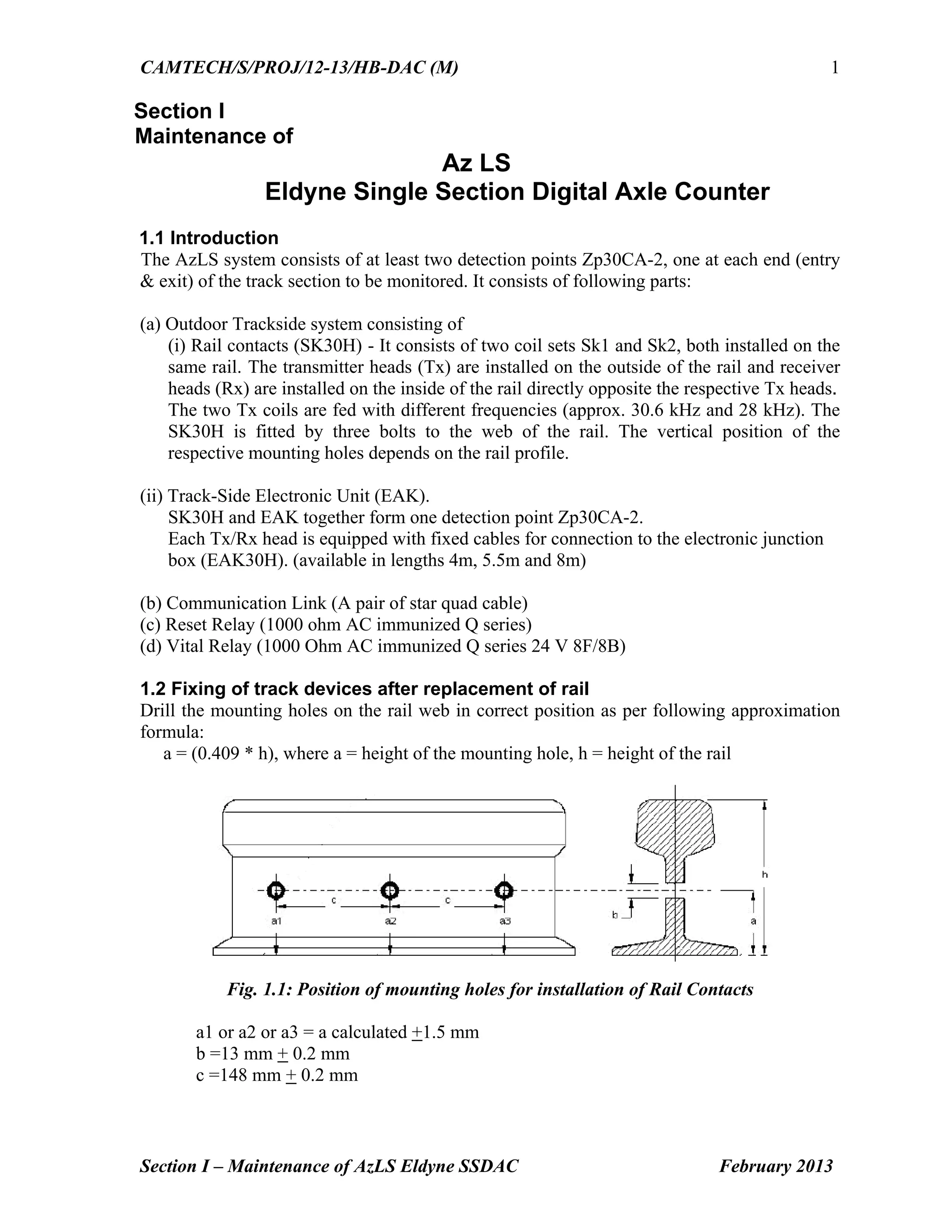
![CAMTECH/S/PROJ/12-13/HB-DAC (M)
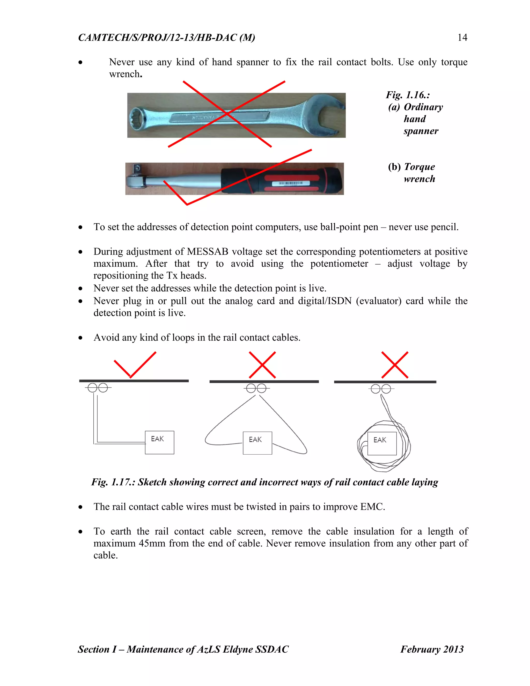
Section I – Maintenance of AzLS Eldyne SSDAC February 2013
2
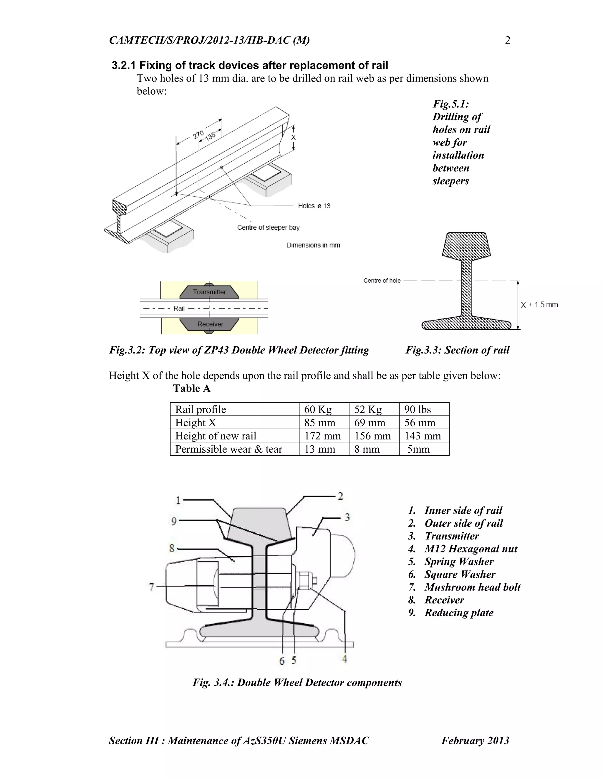
Height of mounting hole for different rail profiles is given below:
Rail Profile 90 lbs 52 Kg 60 Kg
a [mm] 56 mm 63 mm 68 mm
The final three holes of diameter 13mm are drilled on the rail web with the help of drilling
jig. consisting of:
(i) Drilling template
(ii) Mounting device for the drilling machine
(iii)Templates for the standard rail profiles
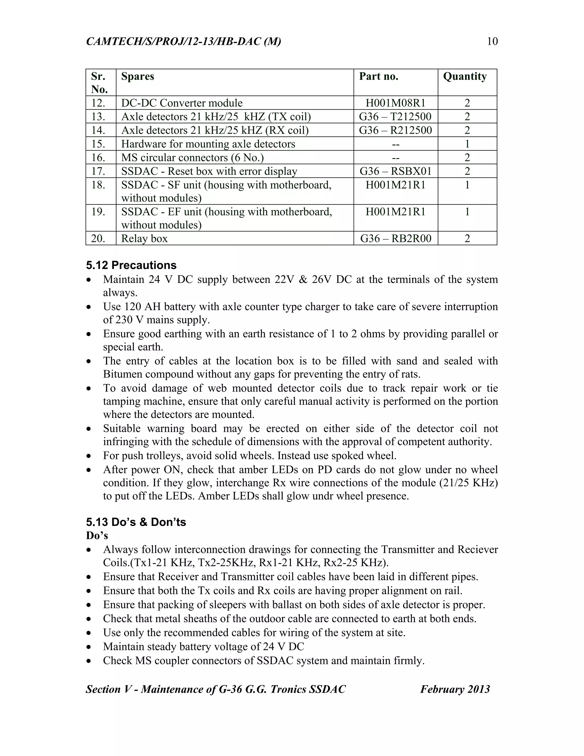
(iv)Fastening device
(v) The drilling machine
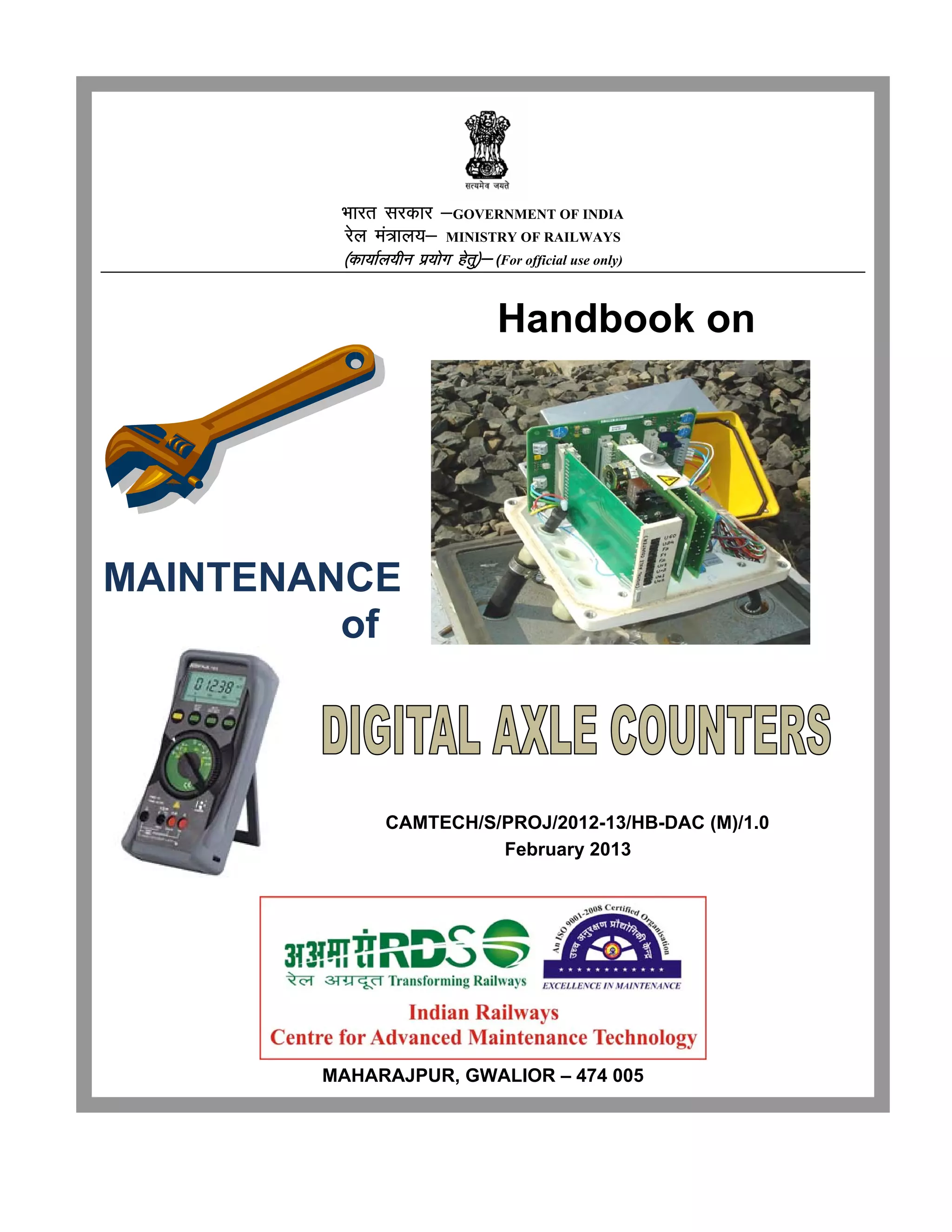
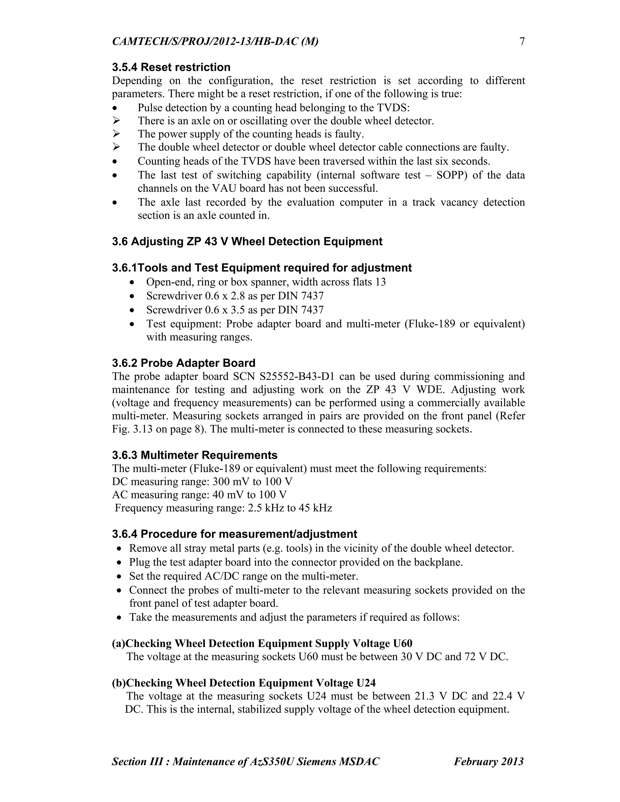
Fig.1.2: Mounting of Rail Contacts
(Tx heads on the outside and Rx heads on the inside of the rail)
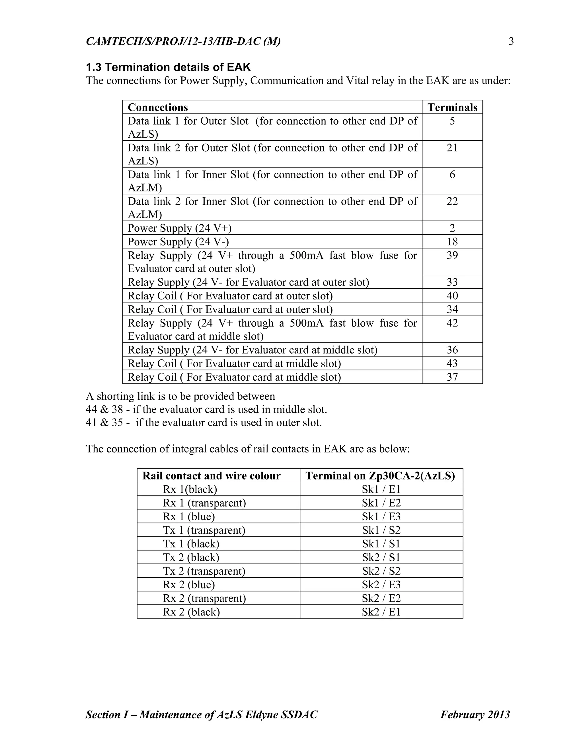
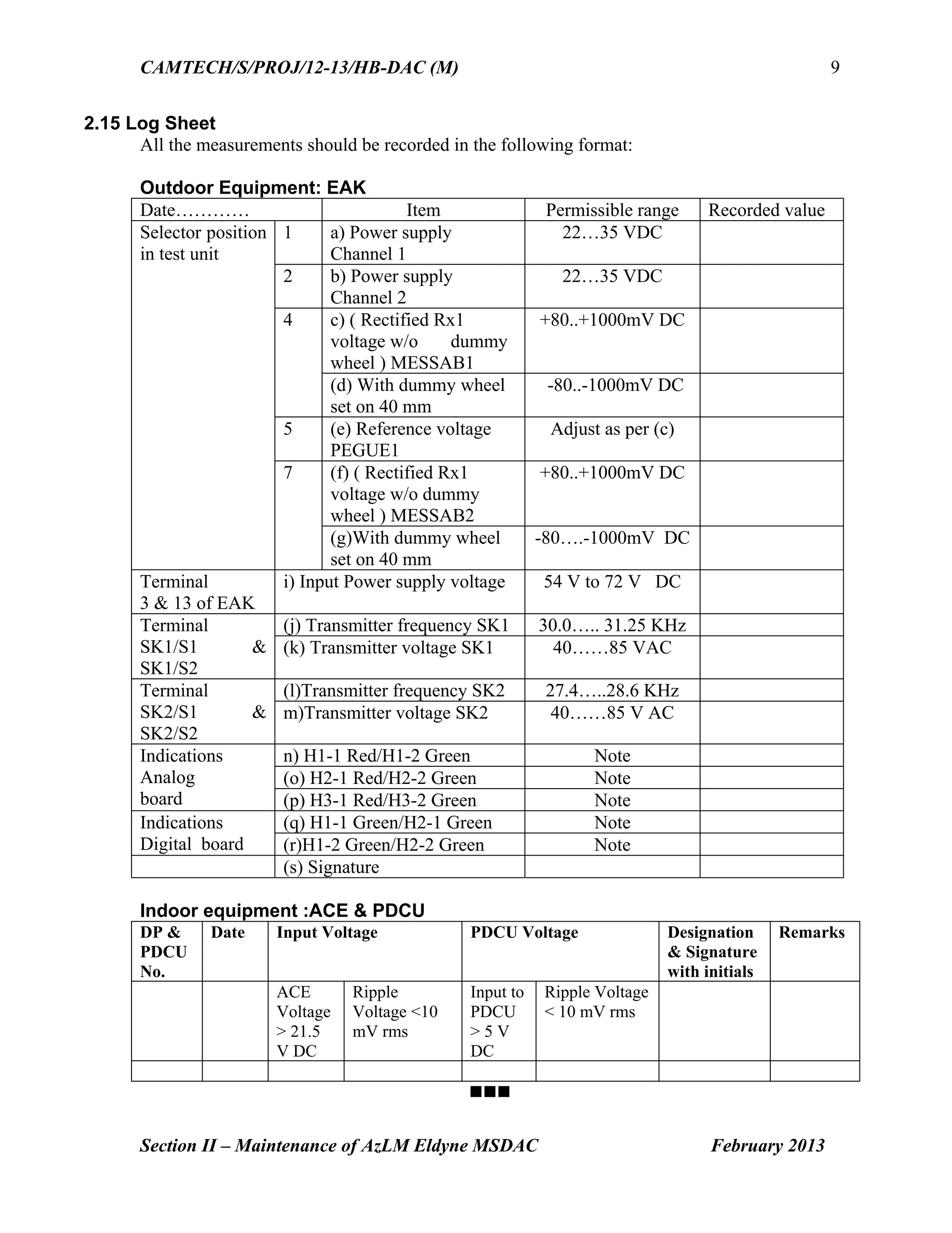
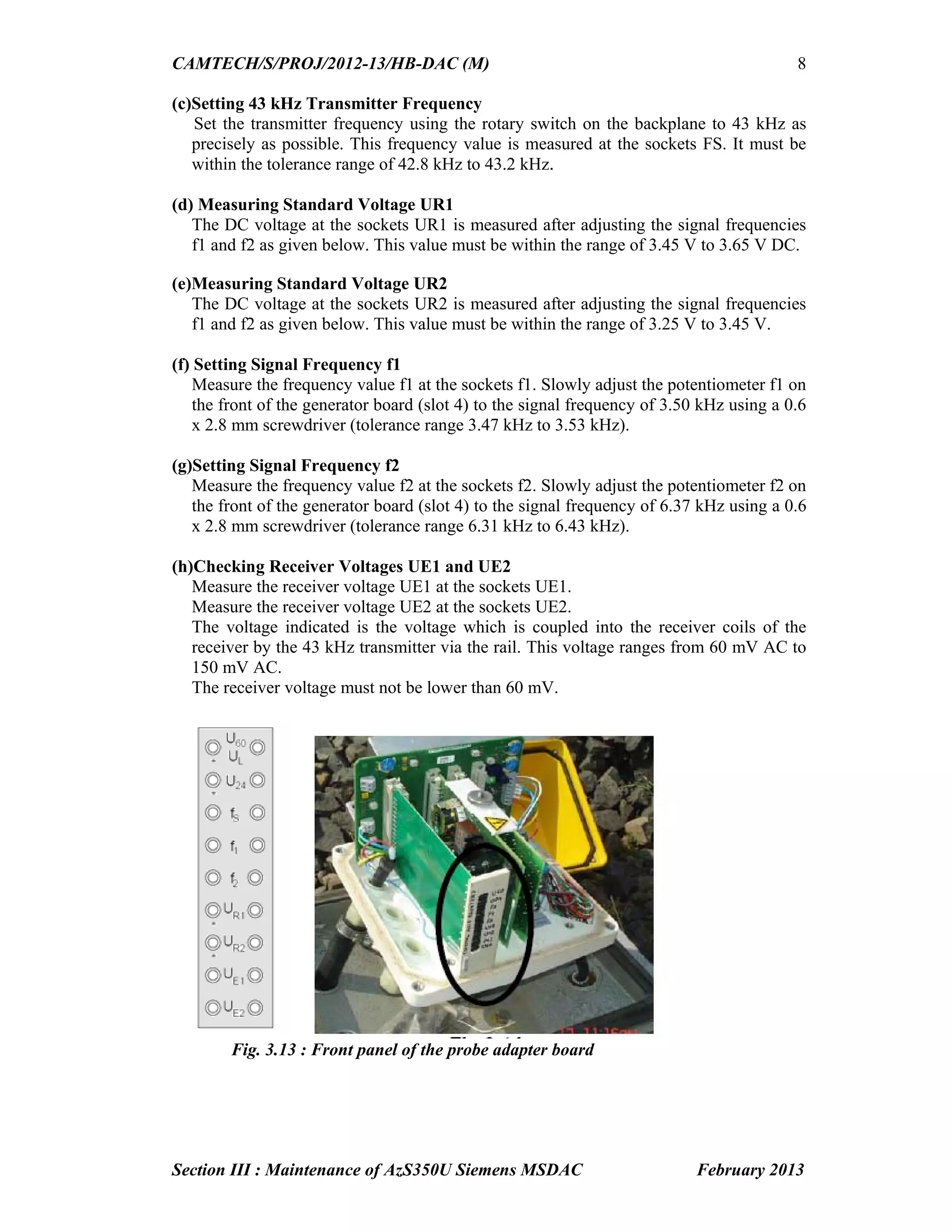
Fig.1.3: EAK backplane assembly (without boards) as viewed from top
1
6a
4
5
3b¹3a¹
2¹
6b
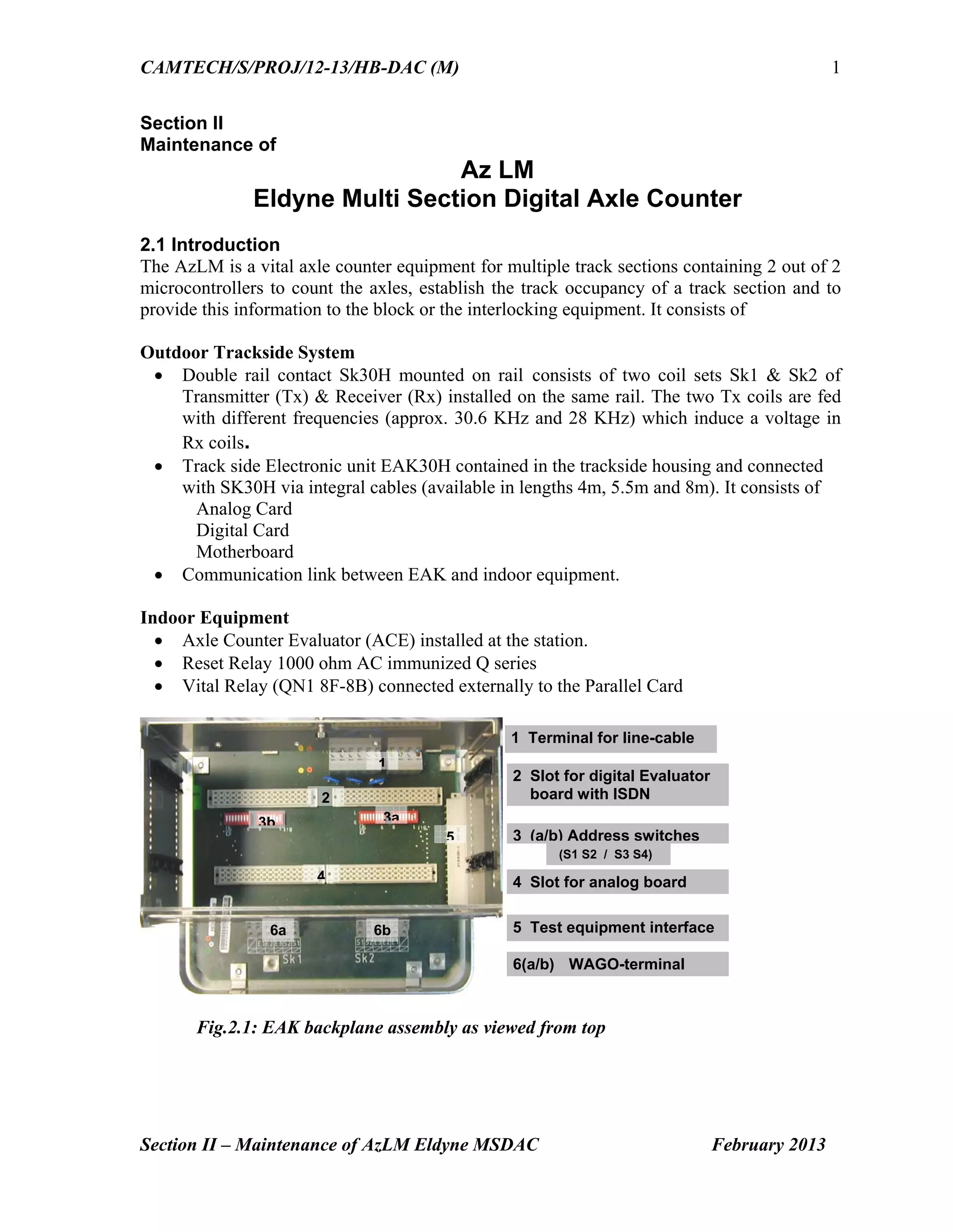
1 Terminal for line-cable
2¹ Slot for Digital Evaluator
/ ISDN Board
3 (a/b) Address switches
5 Test equipment interface
4 Slot for analog board
6(a/b) WAGO-terminal
2² Slot for Digital Board
2²
3b²3a²
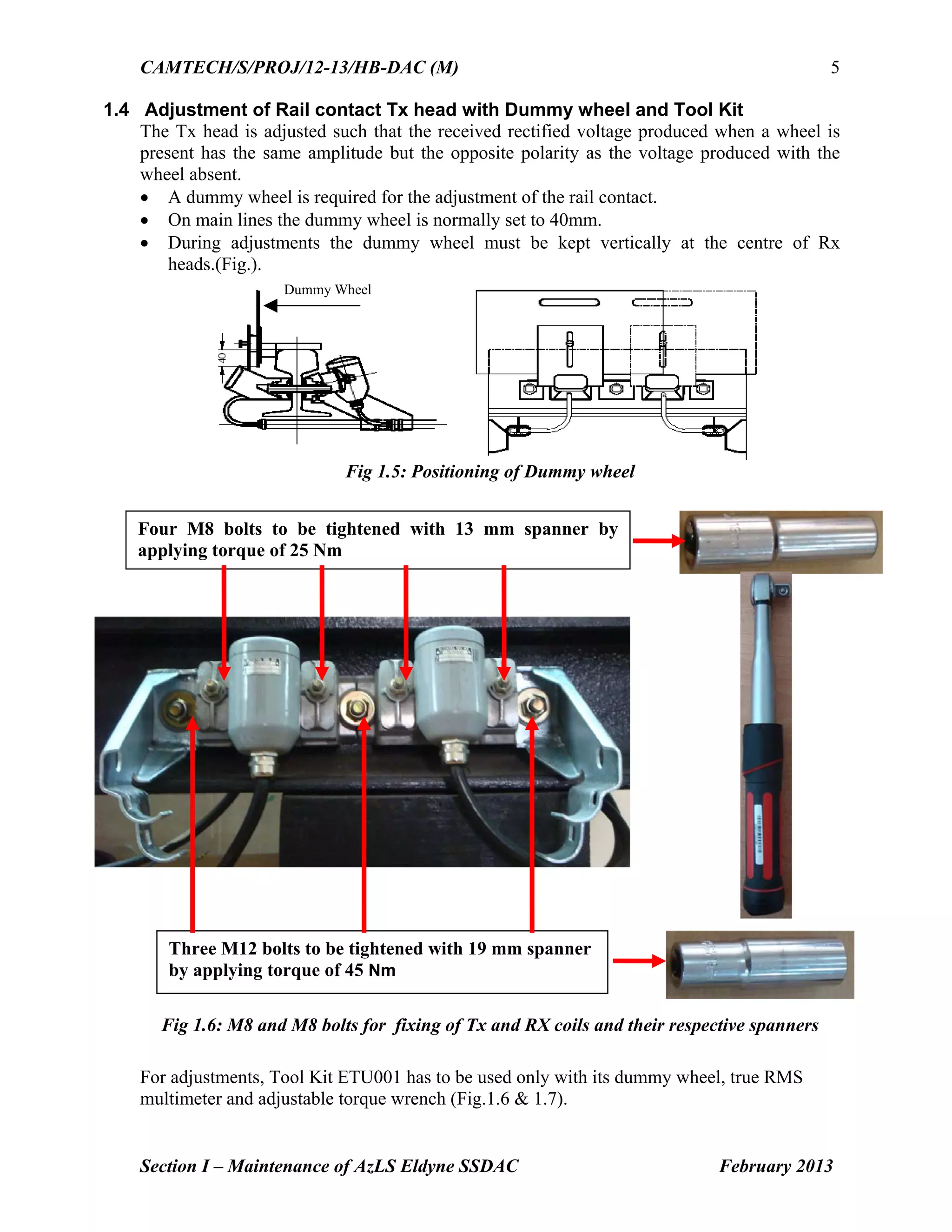
Washer
Nut
Nylon Bush
Insulating Plate
M12 bolt
M8 bolt](https://image.slidesharecdn.com/handbookonmaintenanceofdigitalaxlecounter11-150208044503-conversion-gate01/75/Handbook-on-maintenance-of-digital-axle-counter-10-2048.jpg)


![CAMTECH/S/PROJ/12-13/HB-DAC (M)
Section V - Maintenance of G-36 G.G. Tronics SSDAC February 2013
1
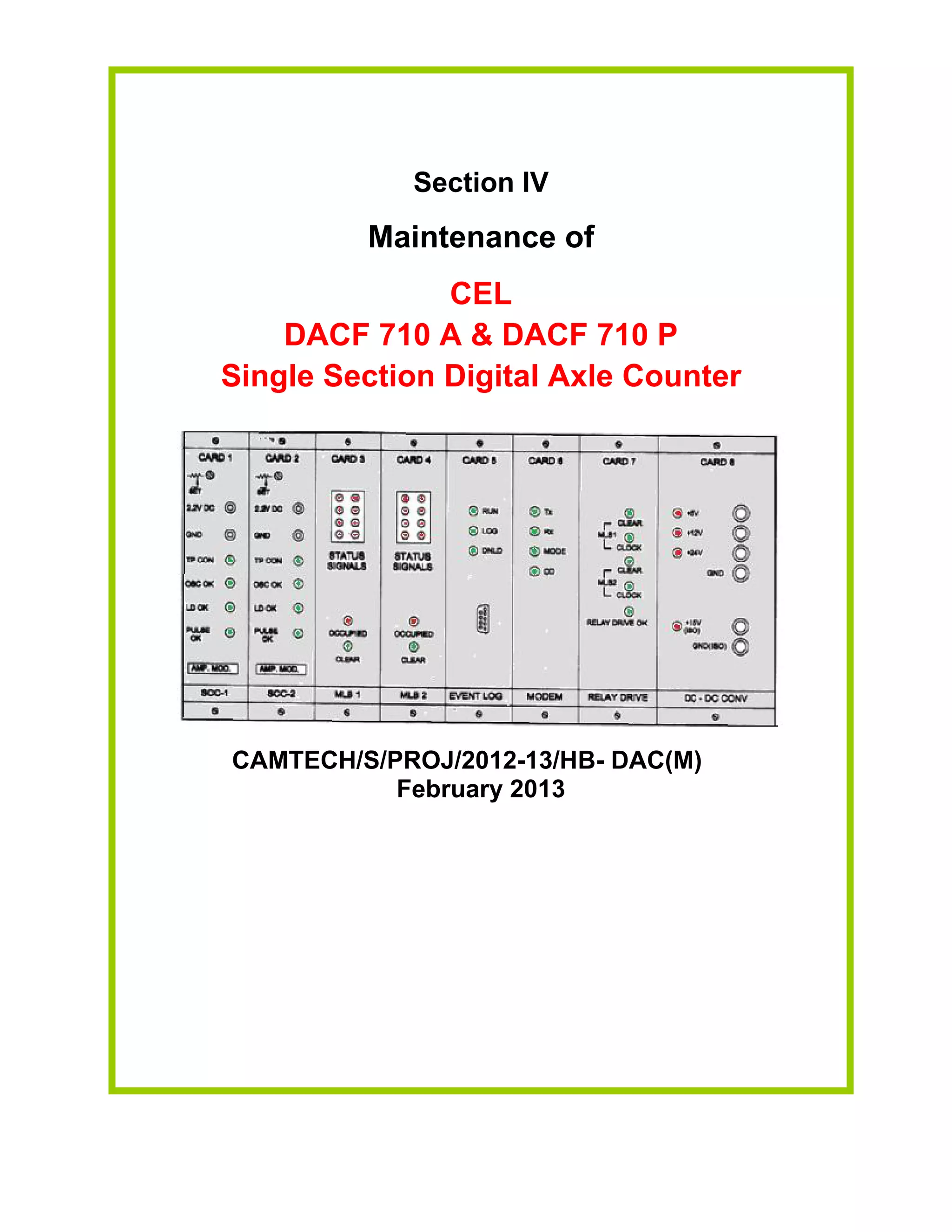
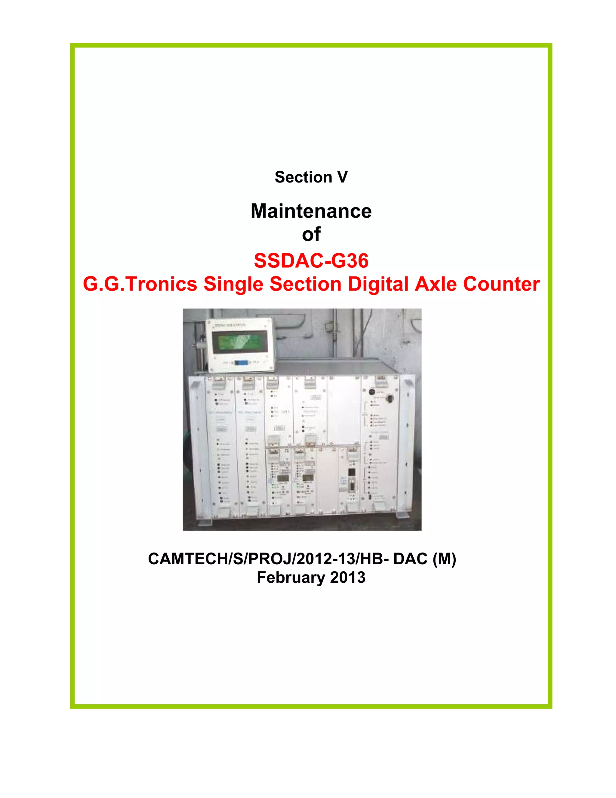
Section V
Maintenance of
SSDAC-G36
G.G.Tronics Single Section Digital Axle Counter
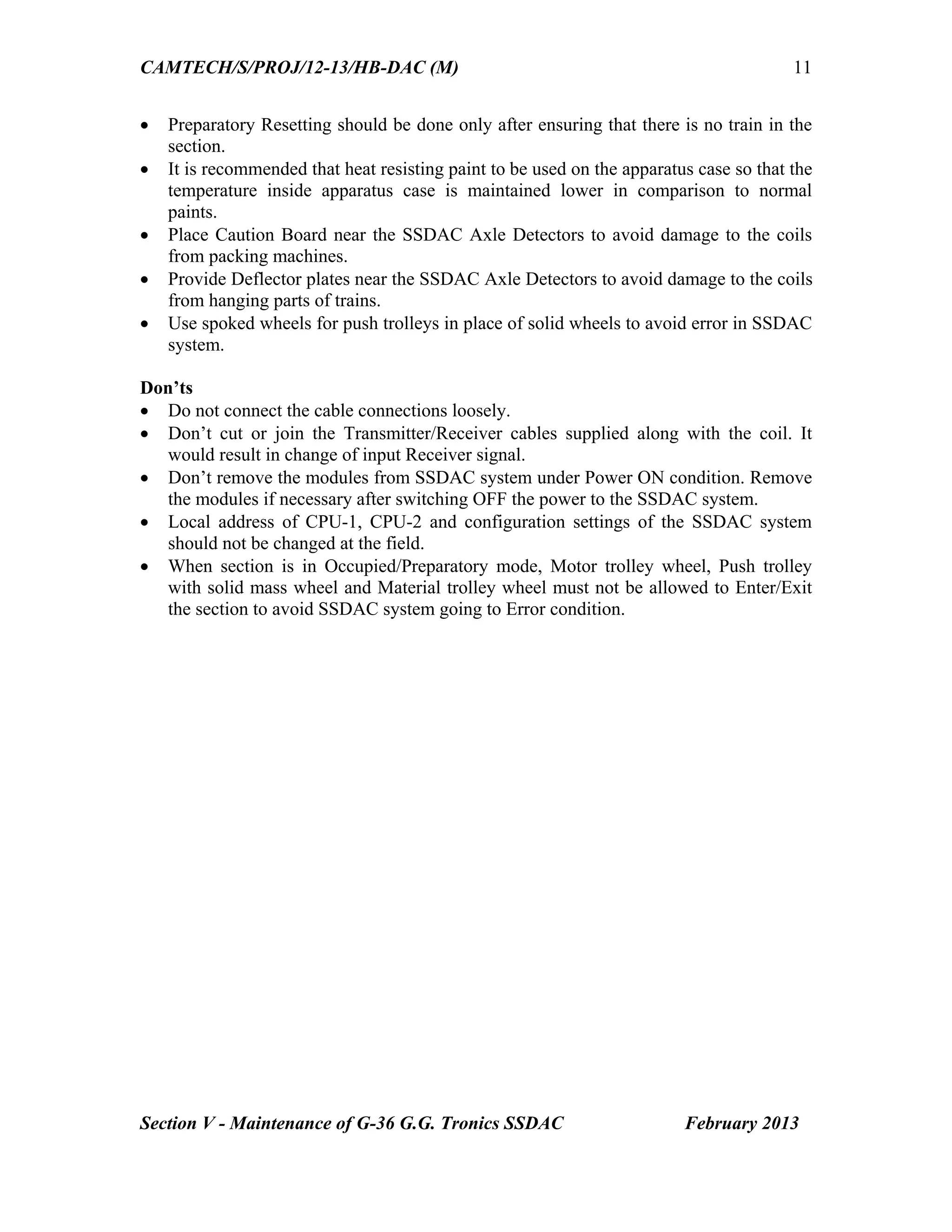
5.1 Introduction
SSDAC G36 manufactured by M/s G.G.Tronics India Pvt. Ltd., is a microcontroller
based system with 2 out of 2 architecture suited for proving station and block section.
5.2 Modules of G36 SSDAC
The hardware and software for all the configurations are same. The main modules for
SSDAC-G36 are listed below:
SSDAC unit
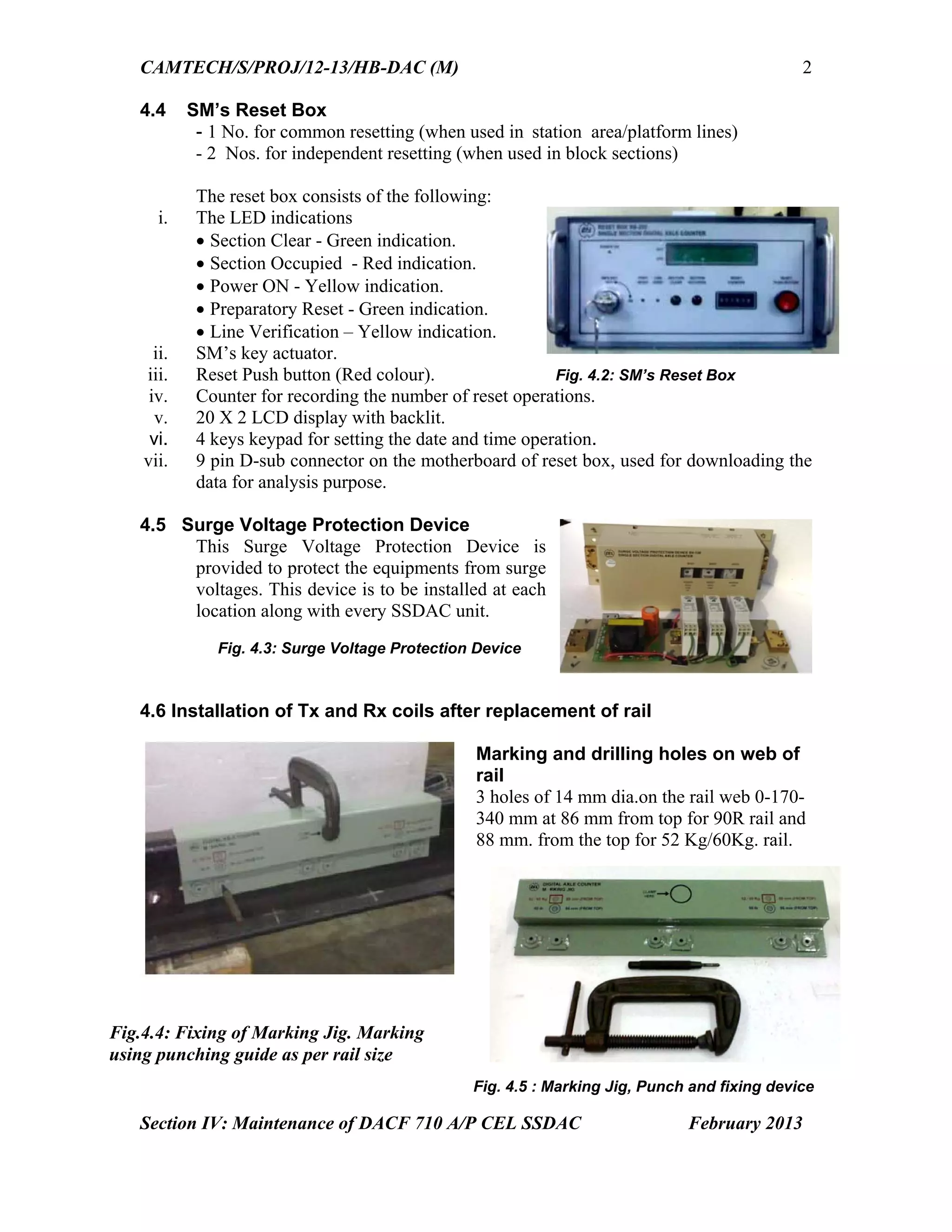
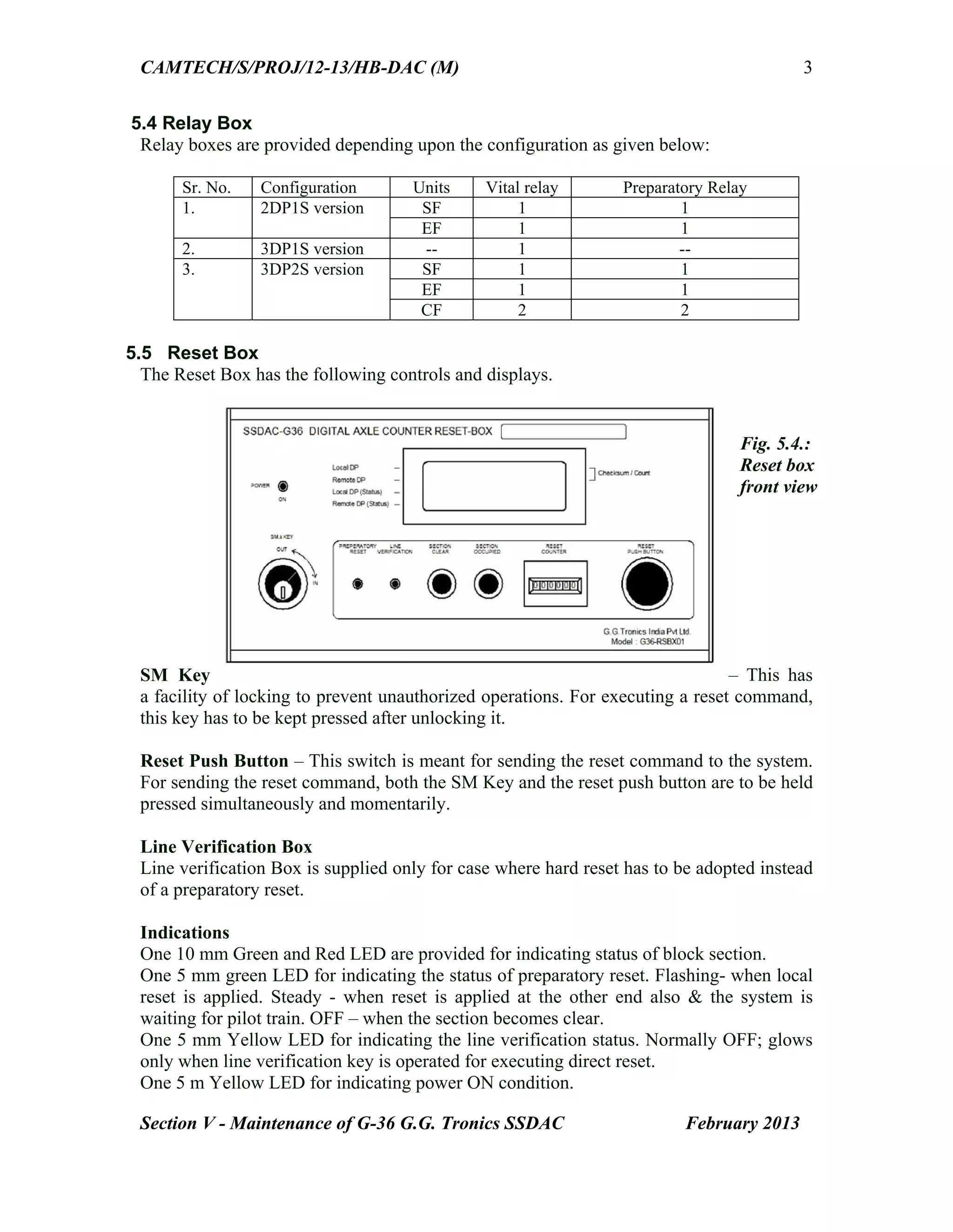
Reset box
Axle Detectors (Tx & Rx coils factory tuned to 21 KHz & 25 KHz with
associated cables of 15 Mtrs.each)
5.3 Configurations
SSDAC-G36 units can be installed to work in the following configurations:
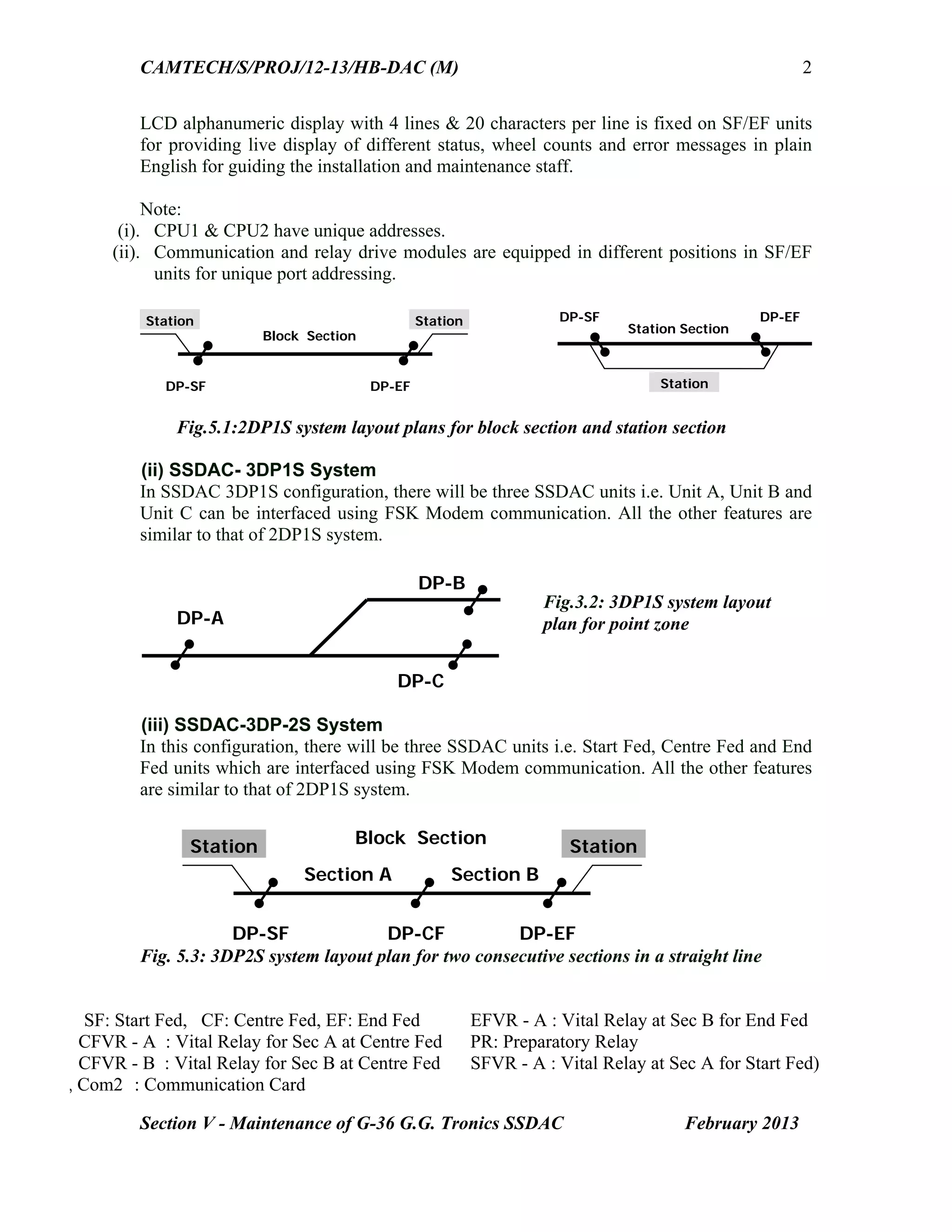
Two detection points Single section: In straight line [2DP1S].
Three detection points Single section: In point zone [3DP1S].
Three-detection points for two consecutive sections in a straight line [3DP2S].
(i) SSDAC 2DP1S system
This system is provided with two detection points on straight lines in station or block
section. It indicates the section as occupied or clear through a Vital Relay (VR) output.
The system consists of Start Fed (SF) and End Fed (EF) units. The SF and EF unit
consists of the following modules:
Phase detector Card 1 - 21 KHz – 1No.
Phase detector Card 2 - 25 KHz – 1 No.
Central Processing Unit 1(CPU1) – 1 No.
Central Processing Unit 2(CPU2) – 1 No.
Communication module – 1No.
Relay Drive Module – 1 No.
SM-CPU /Event logger module – 1 No.
DC/DC Converter – 1 No.
LCD display Module](https://image.slidesharecdn.com/handbookonmaintenanceofdigitalaxlecounter11-150208044503-conversion-gate01/75/Handbook-on-maintenance-of-digital-axle-counter-64-2048.jpg)

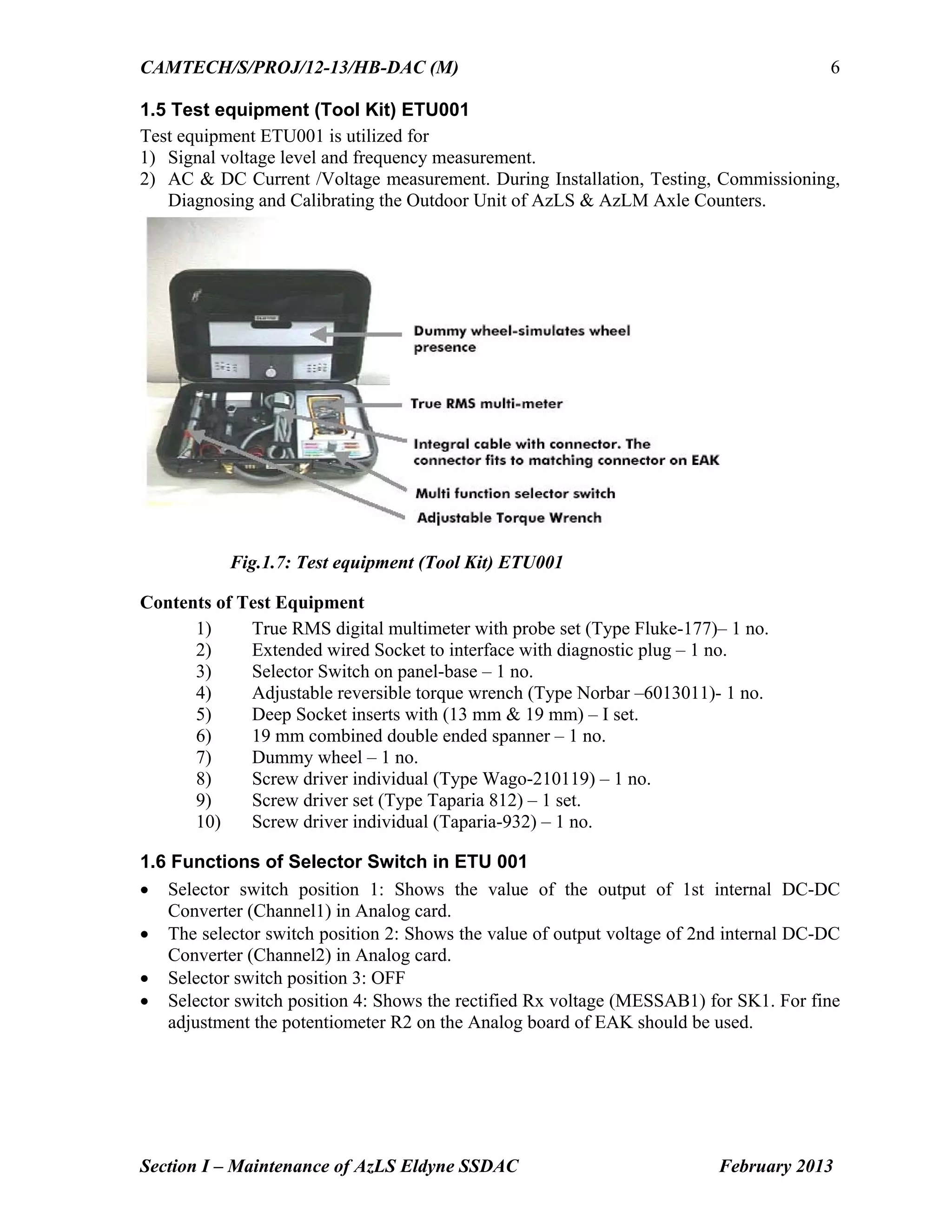
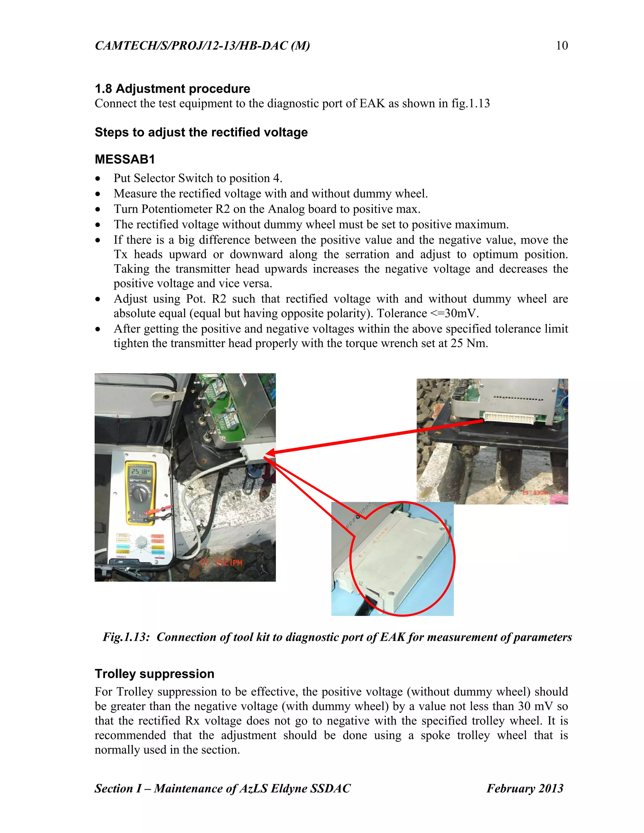
The document provides maintenance information for the Eldyne AzLS single section digital axle counter system. It details procedures for fixing track devices after rail replacement, adjusting rail contact transmit heads using a dummy wheel and test equipment, and resetting the system. Key steps include drilling mounting holes for rail contacts in the correct position, using a test kit to measure signal levels and adjust potentiometers to equalize rectified and reference voltages, and operating the reset box to initiate a reset. Proper maintenance following the guidance helps ensure trouble-free performance of the digital axle counter.
Introduction to the handbook outlining the significance of digital axle counters, safety features, and maintenance structure.
Acknowledgment of contributors, purpose of manual, and guidelines, emphasizing the continuous improvement of railroad safety.
Overview of content structure, detailing sections on maintenance for various digital axle counters such as Eldyne and Siemens.
In-depth maintenance instructions for Eldyne AzLS SSDAC, including installation, adjustments, test procedures, and checklists.
Instructions similar to single section but focused on multi-section systems, detailing adjustment methods and evaluation.
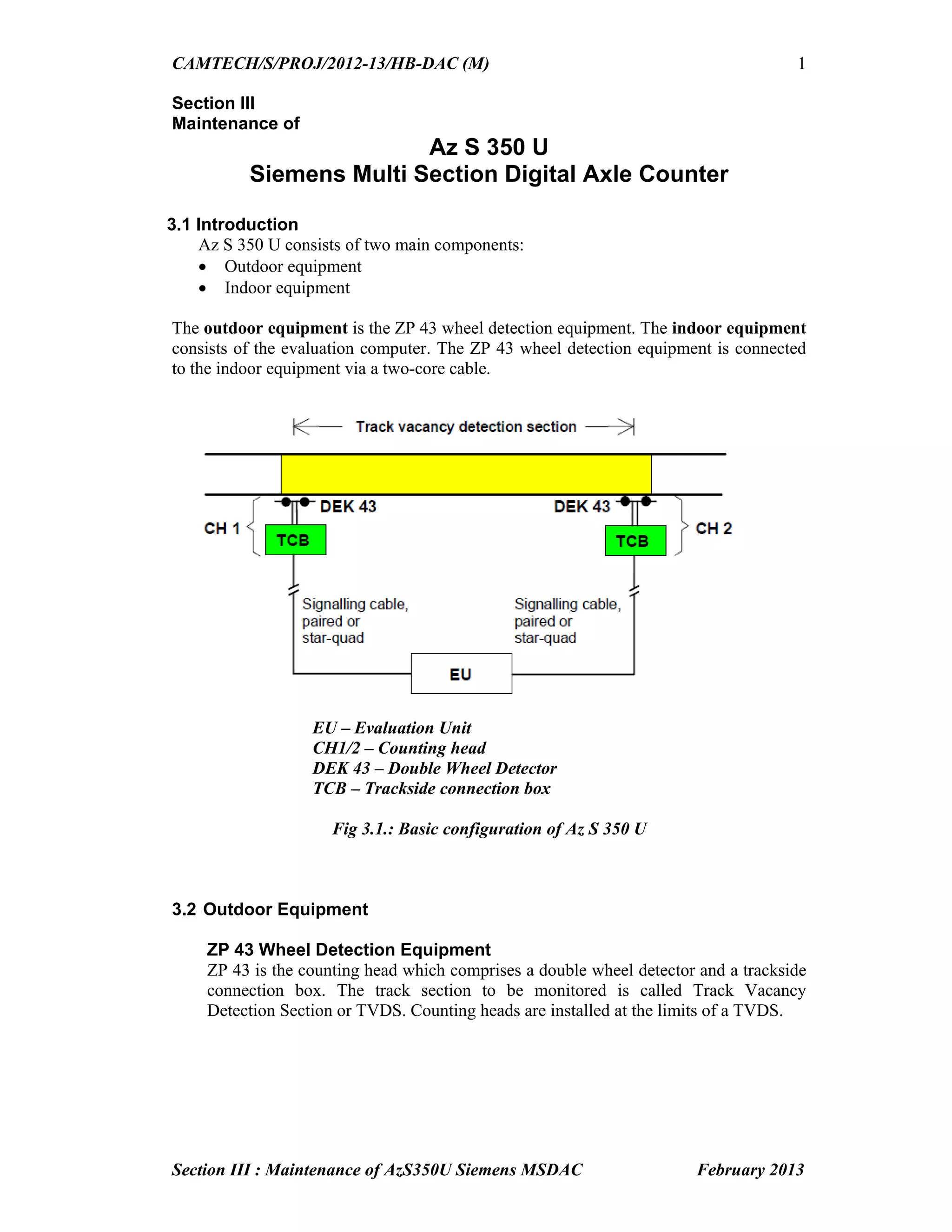
Maintenance procedures for Siemens Az S 350 U, including the setup, voltage checks, and functional testing of components.
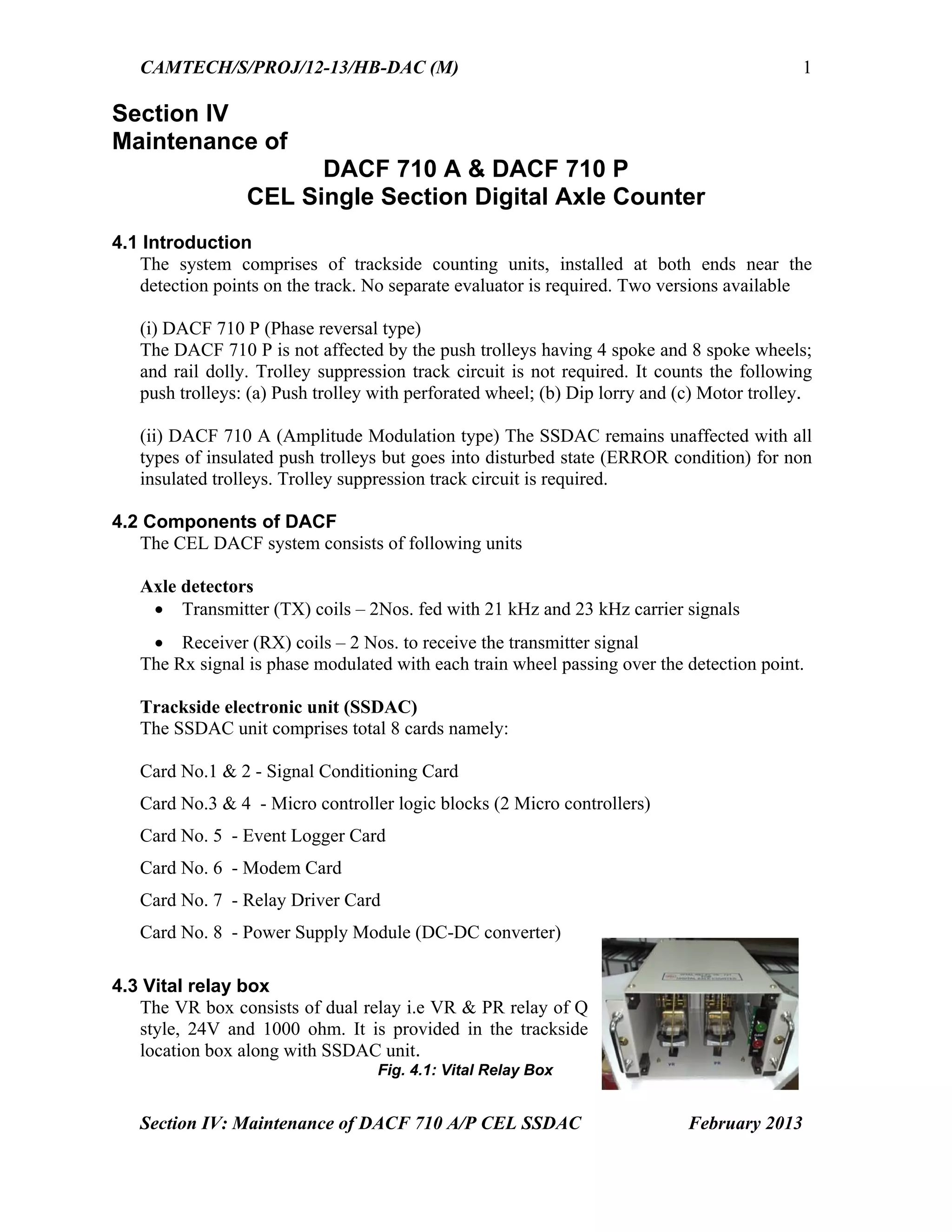
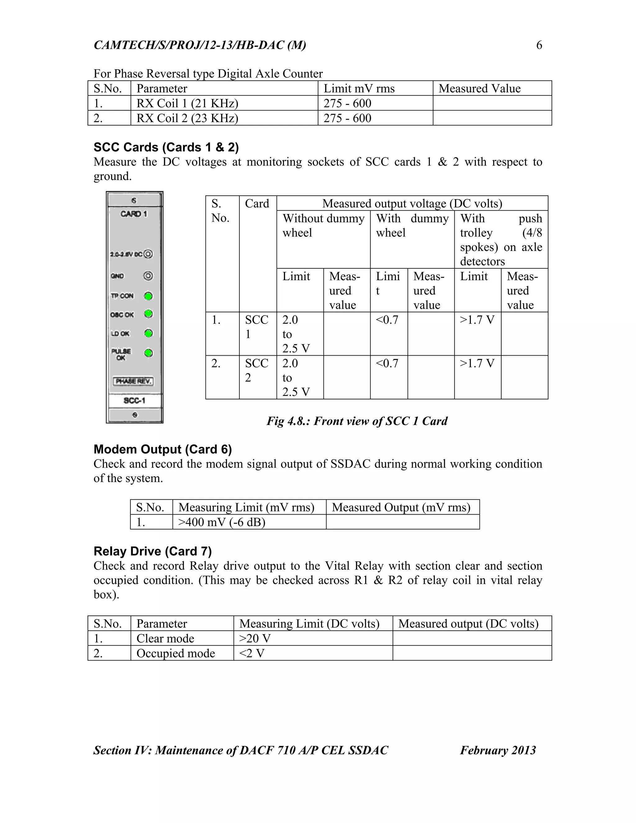
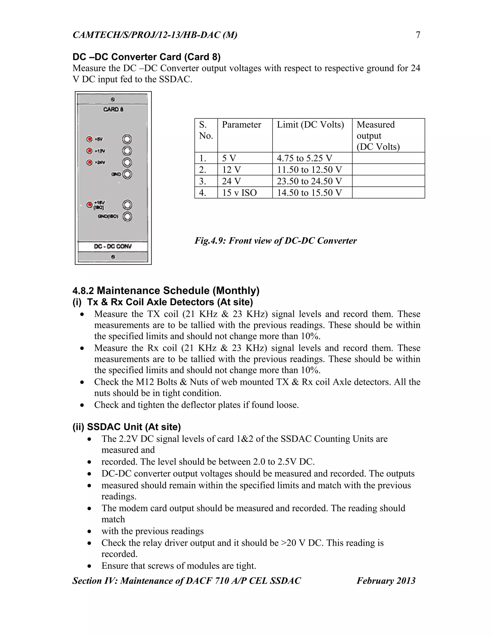
Operational guidelines and maintenance for Cel DACF 710 counters, including configuration details and voltage checks.
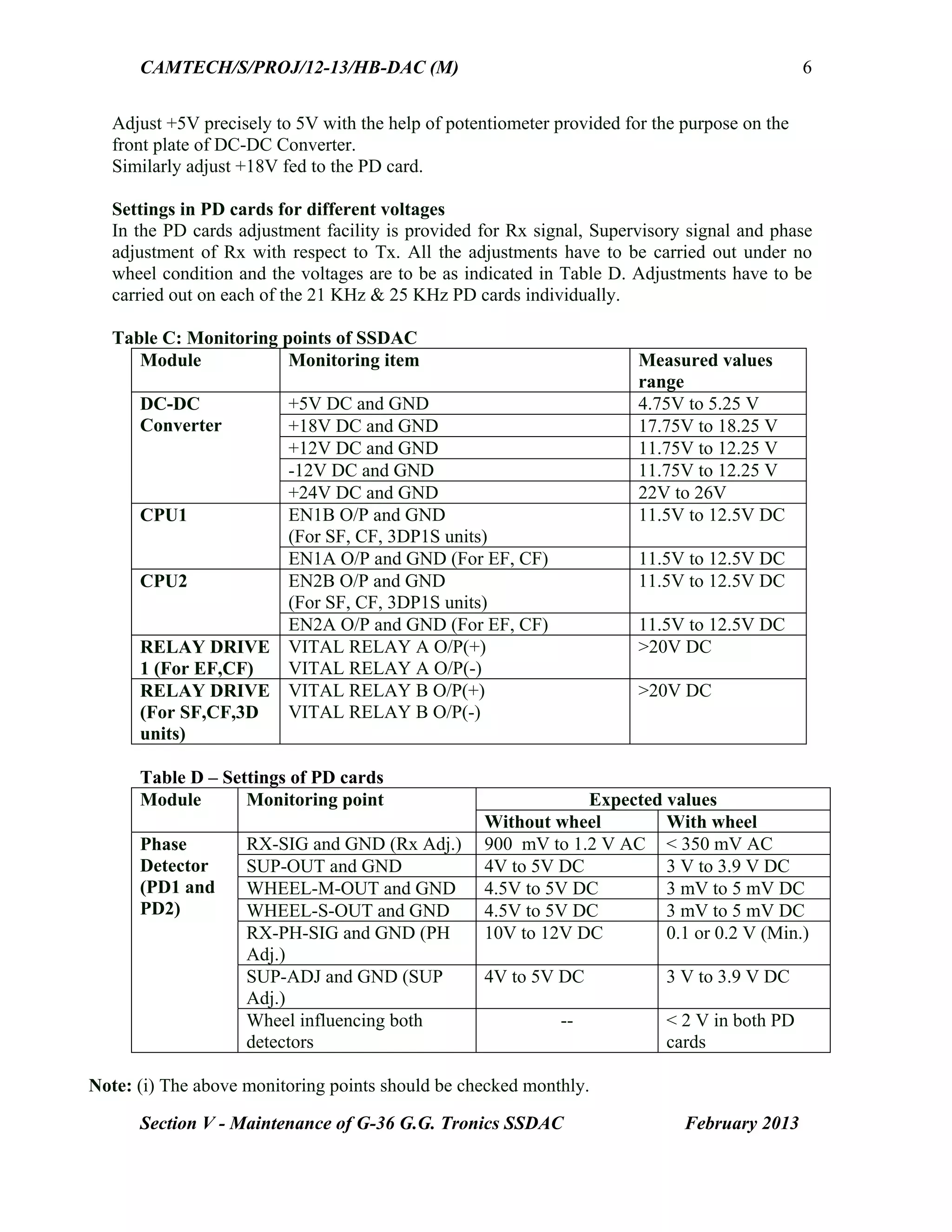
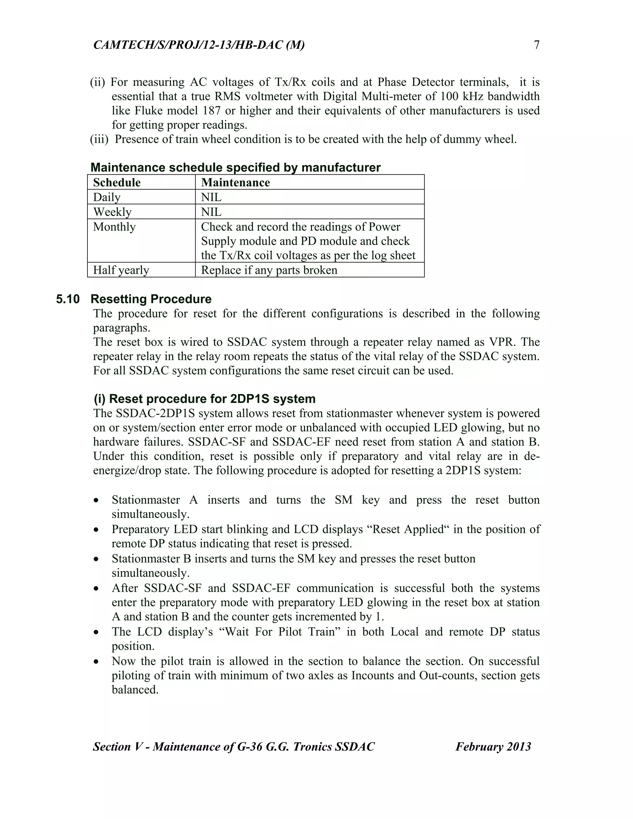
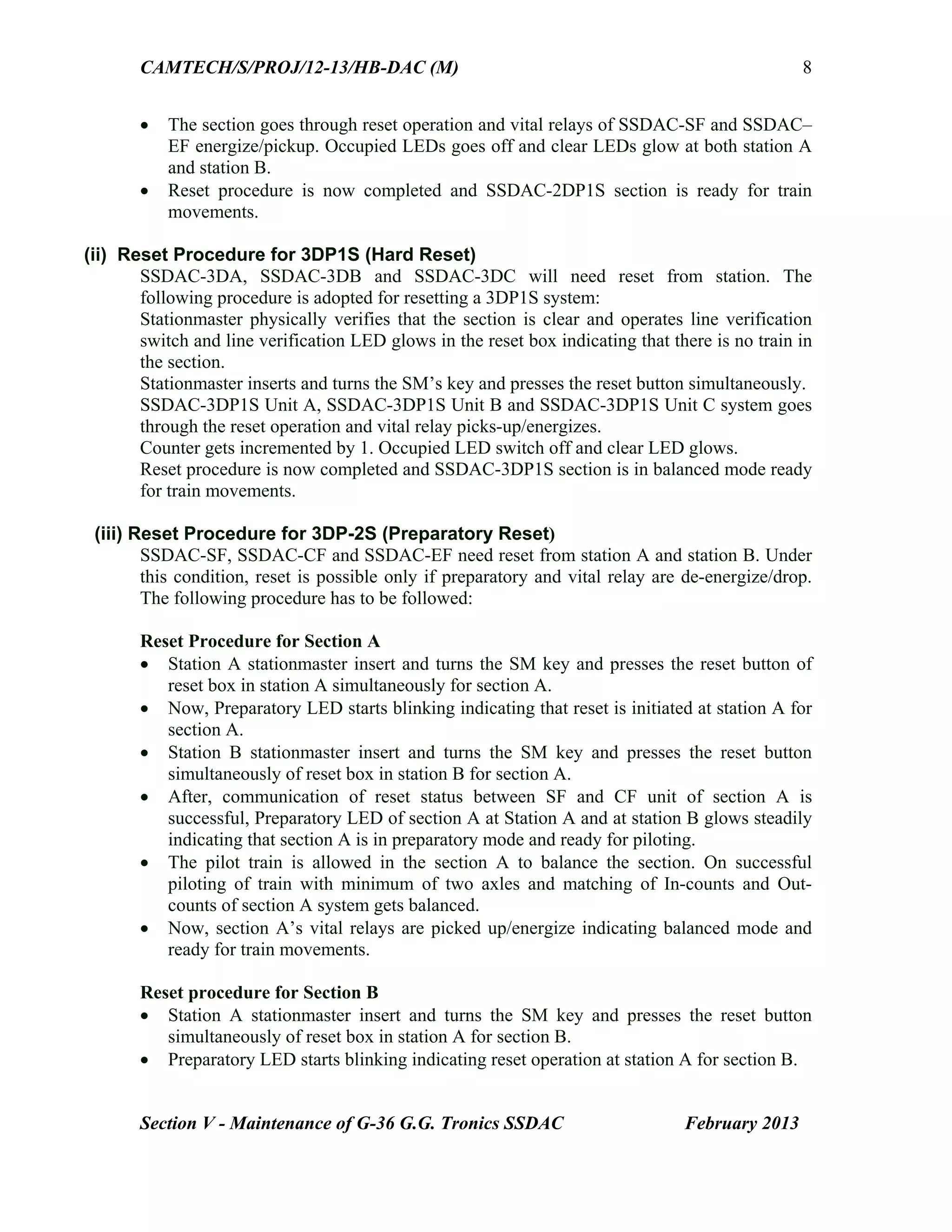
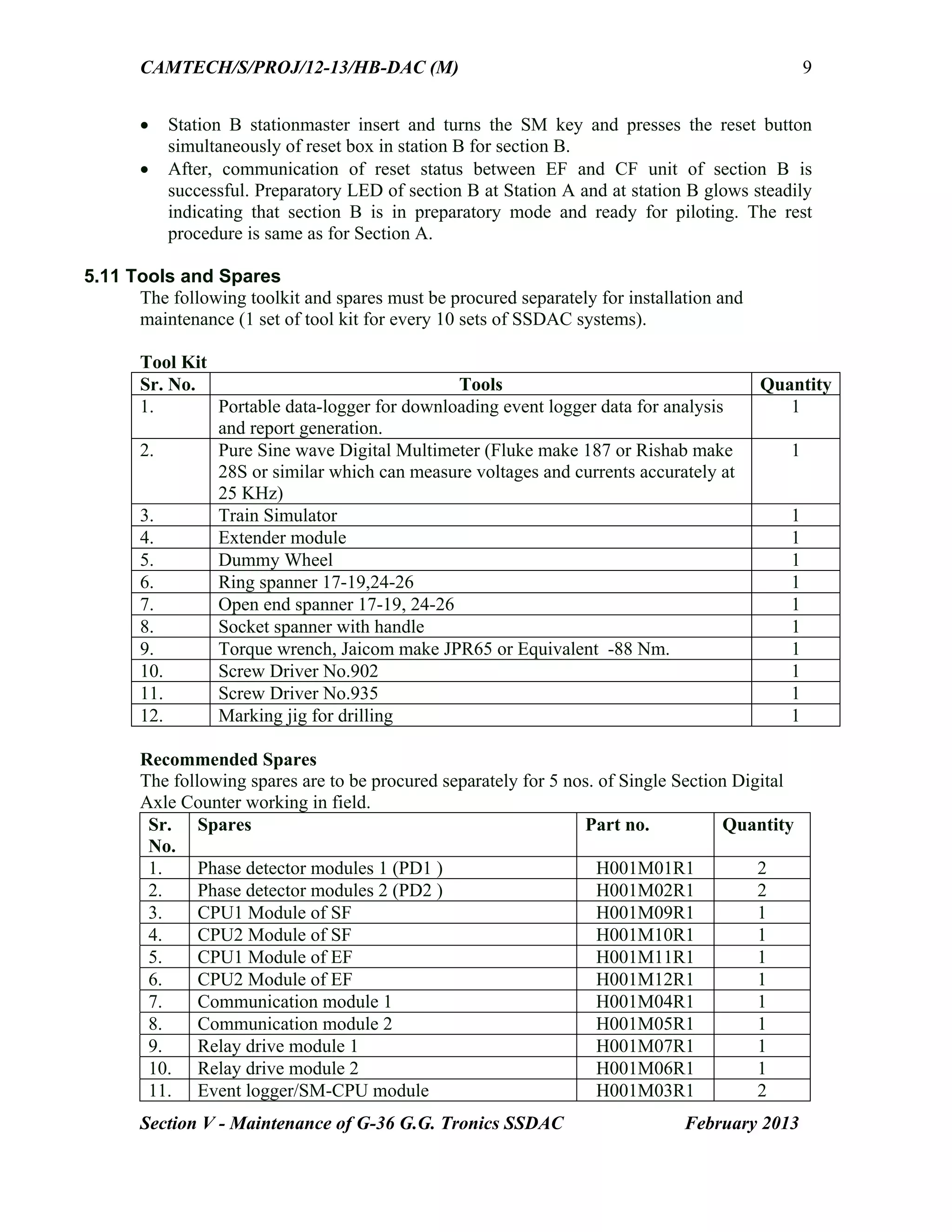
Overview of G36 SSDAC maintenance processes including installation, power supply setup, adjustments, and operational protocols.
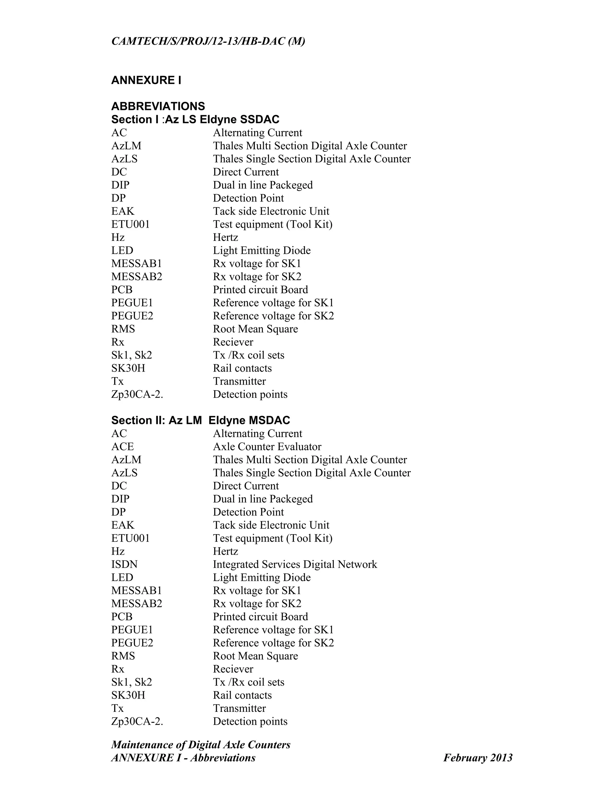
Comprehensive list of abbreviations used in the manual and references that support the information provided in the handbook.