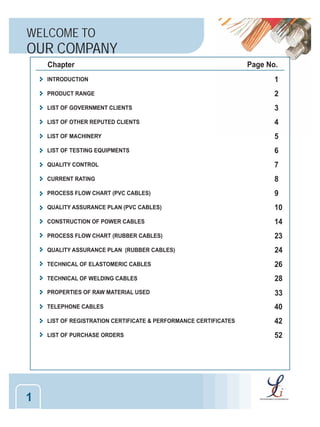
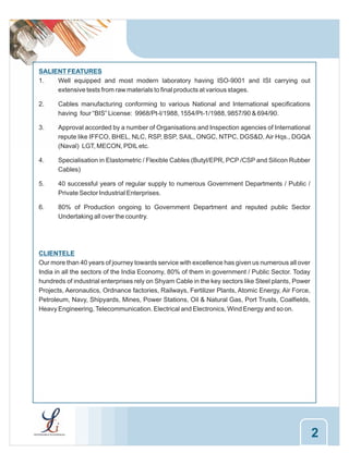
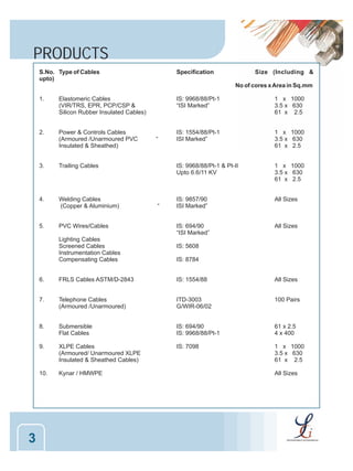
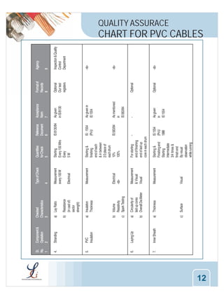
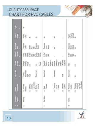
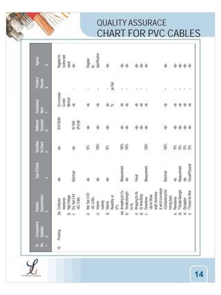
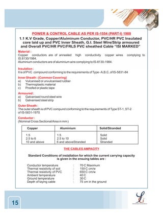
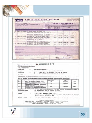
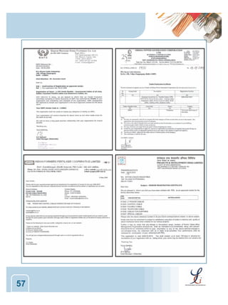
This document provides information about Shyam Cable Industries, which manufactures all types of cables. It includes lists of government and commercial clients, machinery and testing equipment used, quality control processes, current ratings for cables, process flow charts and quality assurance plans for PVC and rubber cables, technical details on elastomeric and welding cables, and properties of raw materials. The company has over 40 years of experience supplying cables to government departments and public/private sector companies across various industries in India. It maintains high quality standards through rigorous material, process and product controls.
Creative, ambitious and knowledgeable engineering professional seeks to utilize my perfect skills and experience in the Electrical Engineering Field (Power & controllers) to meet and exceed all goals in your organization while advancing my own Career.
Electrical Wiring:Types of wires and Cables and the circuit control on domest...maharshi solanki
Electrical Wiring:Types of wires and Cables and the circuit control on domestic installation
Prepared by: Maharshi Solanki
Guided by:Prof. Jaydeep Vanpariya
I have over 11 years of work experience as QA/QC Inspector in Oil and Gas fields both offshore and onshore Construction and installations. focus on PQT/PQR, WQT, NDT, Destructive testing, Inspections of welding and Filed joint coating of Subsea Pipelines, Risers, Tie‐in spools, lateral joints, Jackets, Topside, and Pile pipes. Installation inspection of Pile driving, SPM, PLEMs, I&J tubes, Jackets & top sides.
RAXTON EExe Adaptors, EExd Right Angle Adaptors,EExd Male to Male and
Female to Female Adaptors,EExe Reducers,EExe Stopping Plugs,EExe Breather - Drain Plugs,EExd Compound Stopper Box/Adaptor,Raxton Part Number System,Accessories
Send enquires to mail@akbartrading.com
Complete Description of High Quality Tempsens Make Instrumentation, Control, Signal and Mineral Insulated (MI) Cables and Wires
And Insulation offered on wires and cables.
These Cables and wires covers wide areas of applications in different types of process industries and OEMs.
Metal Bulletin & SMR 7th International Stainless and Special Steel Summit
Hotel Los Monteros, Marbella 12/11/08 - Presentation by Mattia Agnoletto, Sales Director at Inox Tech S.p.A.
Take advantage of professional electrical testing services in Delhi at Spectro Analytical Labs Limited. The company has been offering top rated services to its customers for last two years and has made to the list of best electrical testing labs in Delhi. One of the best set-up electrical testing labs, they provide all types of advance testing services at an affordable price.
Comparision Lightning Protection Systems s per IEC 62305-3 and NFC 17-102(2011)/UNE21-1186 India NBC2016 / Project Building and Infra Projects /MEP ,Architect ,Electrical Consultants
Lightning is Disaster when it's hit to Surface and damage only possible to assess Lost of Human Lives and Assets.
The Agencies who claim Said Protection is from Lightning Product ,Design and Installation is Accordingly EN62305/IEC62305 and NFC17-102 .
Lightning Protection Standard Committee member is from Industries who are having Experience ,Knowledge and they are business man and better know how to safe guard to make more profit from their Business like other Industries.
If we Compare One Area Like Calculation Hight , Lenght and Width as per ZONE 1,2,3&4 Now Threat from Lightning Design as per IEC62305 and Prepare BOQ Considering Reputed Makes from Manufacturer .
According to IEC62305 our Cost will be 3-5 Time High as Compare to NFC17-102.
Now you can understand why IEC do not support NFC .
Latest now CENELEC Given their Acceptance Mentioning IEC 62035 and NFC17-102 not having any Conflict and Claims are Different and Accepted by Countries.
Plz go through presentation.
In India Lightning Documents is adopted under National Disaster and Every State is Declare Documents to offer Awareness Common Public what action they have to do.
NFC17-102 Acceptance in India CERC,SECI,RDSO.CPWD,PWD and Other Industries and Growing because We want to have Protection from Lightning ,
3.0 Project 2_ Developing My Brand Identity Kit.pptxtanyjahb
A personal brand exploration presentation summarizes an individual's unique qualities and goals, covering strengths, values, passions, and target audience. It helps individuals understand what makes them stand out, their desired image, and how they aim to achieve it.
What is the TDS Return Filing Due Date for FY 2024-25.pdfseoforlegalpillers
It is crucial for the taxpayers to understand about the TDS Return Filing Due Date, so that they can fulfill your TDS obligations efficiently. Taxpayers can avoid penalties by sticking to the deadlines and by accurate filing of TDS. Timely filing of TDS will make sure about the availability of tax credits. You can also seek the professional guidance of experts like Legal Pillers for timely filing of the TDS Return.
Discover the innovative and creative projects that highlight my journey throu...dylandmeas
Discover the innovative and creative projects that highlight my journey through Full Sail University. Below, you’ll find a collection of my work showcasing my skills and expertise in digital marketing, event planning, and media production.
Cracking the Workplace Discipline Code Main.pptxWorkforce Group
Cultivating and maintaining discipline within teams is a critical differentiator for successful organisations.
Forward-thinking leaders and business managers understand the impact that discipline has on organisational success. A disciplined workforce operates with clarity, focus, and a shared understanding of expectations, ultimately driving better results, optimising productivity, and facilitating seamless collaboration.
Although discipline is not a one-size-fits-all approach, it can help create a work environment that encourages personal growth and accountability rather than solely relying on punitive measures.
In this deck, you will learn the significance of workplace discipline for organisational success. You’ll also learn
• Four (4) workplace discipline methods you should consider
• The best and most practical approach to implementing workplace discipline.
• Three (3) key tips to maintain a disciplined workplace.
Personal Brand Statement:
As an Army veteran dedicated to lifelong learning, I bring a disciplined, strategic mindset to my pursuits. I am constantly expanding my knowledge to innovate and lead effectively. My journey is driven by a commitment to excellence, and to make a meaningful impact in the world.
Digital Transformation and IT Strategy Toolkit and TemplatesAurelien Domont, MBA
This Digital Transformation and IT Strategy Toolkit was created by ex-McKinsey, Deloitte and BCG Management Consultants, after more than 5,000 hours of work. It is considered the world's best & most comprehensive Digital Transformation and IT Strategy Toolkit. It includes all the Frameworks, Best Practices & Templates required to successfully undertake the Digital Transformation of your organization and define a robust IT Strategy.
Editable Toolkit to help you reuse our content: 700 Powerpoint slides | 35 Excel sheets | 84 minutes of Video training
This PowerPoint presentation is only a small preview of our Toolkits. For more details, visit www.domontconsulting.com
[Note: This is a partial preview. To download this presentation, visit:
https://www.oeconsulting.com.sg/training-presentations]
Sustainability has become an increasingly critical topic as the world recognizes the need to protect our planet and its resources for future generations. Sustainability means meeting our current needs without compromising the ability of future generations to meet theirs. It involves long-term planning and consideration of the consequences of our actions. The goal is to create strategies that ensure the long-term viability of People, Planet, and Profit.
Leading companies such as Nike, Toyota, and Siemens are prioritizing sustainable innovation in their business models, setting an example for others to follow. In this Sustainability training presentation, you will learn key concepts, principles, and practices of sustainability applicable across industries. This training aims to create awareness and educate employees, senior executives, consultants, and other key stakeholders, including investors, policymakers, and supply chain partners, on the importance and implementation of sustainability.
LEARNING OBJECTIVES
1. Develop a comprehensive understanding of the fundamental principles and concepts that form the foundation of sustainability within corporate environments.
2. Explore the sustainability implementation model, focusing on effective measures and reporting strategies to track and communicate sustainability efforts.
3. Identify and define best practices and critical success factors essential for achieving sustainability goals within organizations.
CONTENTS
1. Introduction and Key Concepts of Sustainability
2. Principles and Practices of Sustainability
3. Measures and Reporting in Sustainability
4. Sustainability Implementation & Best Practices
To download the complete presentation, visit: https://www.oeconsulting.com.sg/training-presentations
Buy Verified PayPal Account | Buy Google 5 Star Reviewsusawebmarket
Buy Verified PayPal Account
Looking to buy verified PayPal accounts? Discover 7 expert tips for safely purchasing a verified PayPal account in 2024. Ensure security and reliability for your transactions.
PayPal Services Features-
🟢 Email Access
🟢 Bank Added
🟢 Card Verified
🟢 Full SSN Provided
🟢 Phone Number Access
🟢 Driving License Copy
🟢 Fasted Delivery
Client Satisfaction is Our First priority. Our services is very appropriate to buy. We assume that the first-rate way to purchase our offerings is to order on the website. If you have any worry in our cooperation usually You can order us on Skype or Telegram.
24/7 Hours Reply/Please Contact
usawebmarketEmail: support@usawebmarket.com
Skype: usawebmarket
Telegram: @usawebmarket
WhatsApp: +1(218) 203-5951
USA WEB MARKET is the Best Verified PayPal, Payoneer, Cash App, Skrill, Neteller, Stripe Account and SEO, SMM Service provider.100%Satisfection granted.100% replacement Granted.
VAT Registration Outlined In UAE: Benefits and Requirementsuae taxgpt
Vat Registration is a legal obligation for businesses meeting the threshold requirement, helping companies avoid fines and ramifications. Contact now!
https://viralsocialtrends.com/vat-registration-outlined-in-uae/
Memorandum Of Association Constitution of Company.pptseri bangash
www.seribangash.com
A Memorandum of Association (MOA) is a legal document that outlines the fundamental principles and objectives upon which a company operates. It serves as the company's charter or constitution and defines the scope of its activities. Here's a detailed note on the MOA:
Contents of Memorandum of Association:
Name Clause: This clause states the name of the company, which should end with words like "Limited" or "Ltd." for a public limited company and "Private Limited" or "Pvt. Ltd." for a private limited company.
https://seribangash.com/article-of-association-is-legal-doc-of-company/
Registered Office Clause: It specifies the location where the company's registered office is situated. This office is where all official communications and notices are sent.
Objective Clause: This clause delineates the main objectives for which the company is formed. It's important to define these objectives clearly, as the company cannot undertake activities beyond those mentioned in this clause.
www.seribangash.com
Liability Clause: It outlines the extent of liability of the company's members. In the case of companies limited by shares, the liability of members is limited to the amount unpaid on their shares. For companies limited by guarantee, members' liability is limited to the amount they undertake to contribute if the company is wound up.
https://seribangash.com/promotors-is-person-conceived-formation-company/
Capital Clause: This clause specifies the authorized capital of the company, i.e., the maximum amount of share capital the company is authorized to issue. It also mentions the division of this capital into shares and their respective nominal value.
Association Clause: It simply states that the subscribers wish to form a company and agree to become members of it, in accordance with the terms of the MOA.
Importance of Memorandum of Association:
Legal Requirement: The MOA is a legal requirement for the formation of a company. It must be filed with the Registrar of Companies during the incorporation process.
Constitutional Document: It serves as the company's constitutional document, defining its scope, powers, and limitations.
Protection of Members: It protects the interests of the company's members by clearly defining the objectives and limiting their liability.
External Communication: It provides clarity to external parties, such as investors, creditors, and regulatory authorities, regarding the company's objectives and powers.
https://seribangash.com/difference-public-and-private-company-law/
Binding Authority: The company and its members are bound by the provisions of the MOA. Any action taken beyond its scope may be considered ultra vires (beyond the powers) of the company and therefore void.
Amendment of MOA:
While the MOA lays down the company's fundamental principles, it is not entirely immutable. It can be amended, but only under specific circumstances and in compliance with legal procedures. Amendments typically require shareholder
Kseniya Leshchenko: Shared development support service model as the way to ma...Lviv Startup Club
Kseniya Leshchenko: Shared development support service model as the way to make small projects with small budgets profitable for the company (UA)
Kyiv PMDay 2024 Summer
Website – www.pmday.org
Youtube – https://www.youtube.com/startuplviv
FB – https://www.facebook.com/pmdayconference
Putting the SPARK into Virtual Training.pptxCynthia Clay
This 60-minute webinar, sponsored by Adobe, was delivered for the Training Mag Network. It explored the five elements of SPARK: Storytelling, Purpose, Action, Relationships, and Kudos. Knowing how to tell a well-structured story is key to building long-term memory. Stating a clear purpose that doesn't take away from the discovery learning process is critical. Ensuring that people move from theory to practical application is imperative. Creating strong social learning is the key to commitment and engagement. Validating and affirming participants' comments is the way to create a positive learning environment.
2. WELCOME TO
OUR COMPANY
Chapter
Page No.
INTRODUCTION
PRODUCT RANGE
2
LIST OF GOVERNMENT CLIENTS
3
LIST OF OTHER REPUTED CLIENTS
4
LIST OF MACHINERY
5
LIST OF TESTING EQUIPMENTS
6
QUALITY CONTROL
7
CURRENT RATING
8
PROCESS FLOW CHART (PVC CABLES)
9
QUALITY ASSURANCE PLAN (PVC CABLES)
10
CONSTRUCTION OF POWER CABLES
14
PROCESS FLOW CHART (RUBBER CABLES)
23
QUALITY ASSURANCE PLAN (RUBBER CABLES)
24
TECHNICAL OF ELASTOMERIC CABLES
26
TECHNICAL OF WELDING CABLES
28
PROPERTIES OF RAW MATERIAL USED
33
TELEPHONE CABLES
40
LIST OF REGISTRATION CERTIFICATE & PERFORMANCE CERTIFICATES
42
LIST OF PURCHASE ORDERS
1
1
52
3. SALIENT FEATURES
1.
Well equipped and most modern laboratory having ISO-9001 and ISI carrying out
extensive tests from raw materials to final products at various stages.
2.
Cables manufacturing conforming to various National and International specifications
having four “BIS” License: 9968/Pt-I/1988, 1554/Pt-1/1988, 9857/90 & 694/90.
3.
Approval accorded by a number of Organisations and Inspection agencies of International
repute like IFFCO, BHEL, NLC, RSP, BSP, SAIL, ONGC, NTPC, DGS&D, Air Hqs., DGQA
(Naval) LGT, MECON, PDIL etc.
4.
Specialisation in Elastometric / Flexible Cables (Butyl/EPR, PCP /CSP and Silicon Rubber
Cables)
5.
40 successful years of regular supply to numerous Government Departments / Public /
Private Sector Industrial Enterprises.
6.
80% of Production ongoing to Government Department and reputed public Sector
Undertaking all over the country.
CLIENTELE
Our more than 40 years of journey towards service with excellence has given us numerous all over
India in all the sectors of the India Economy, 80% of them in government / Public Sector. Today
hundreds of industrial enterprises rely on Shyam Cable in the key sectors like Steel plants, Power
Projects, Aeronautics, Ordnance factories, Railways, Fertilizer Plants, Atomic Energy, Air Force,
Petroleum, Navy, Shipyards, Mines, Power Stations, Oil & Natural Gas, Port Trusts, Coalfields,
Heavy Engineering, Telecommunication. Electrical and Electronics, Wind Energy and so on.
2
4. PRODUCTS
S.No. Type of Cables
upto)
Specification
Size (Including &
No of cores x Area in Sq.mm
1.
Elastomeric Cables
(VIR/TRS, EPR, PCP/CSP &
Silicon Rubber Insulated Cables)
2.
Power & Controls Cables
(Armoured /Unarmoured PVC
Insulated & Sheathed)
3.
Welding Cables
(Copper & Aluminium)
5.
PVC Wires/Cables
Lighting Cables
Screened Cables
Instrumentation Cables
Compensating Cables
“
1 x 1000
3.5 x 630
61 x 2.5
IS: 1554/88/Pt-1
ISI Marked”
1 x 1000
3.5 x 630
61 x 2.5
IS: 9968/88/Pt-1 & Pt-II
Upto 6.6/11 KV
“
Trailing Cables
4.
IS: 9968/88/Pt-1
“ISI Marked”
1 x 1000
3.5 x 630
61 x 2.5
IS: 9857/90
ISI Marked”
All Sizes
IS: 694/90
“ISI Marked”
All Sizes
IS: 5608
IS: 8784
6.
IS: 1554/88
All Sizes
7.
Telephone Cables
(Armoured /Unarmoured)
ITD-3003
G/WIR-06/02
100 Pairs
8.
Submersible
Flat Cables
IS: 694/90
IS: 9968/88/Pt-1
61 x 2.5
4 x 400
9.
XLPE Cables
(Armoured/ Unarmoured XLPE
Insulated & Sheathed Cables)
IS: 7098
1 x 1000
3.5 x 630
61 x 2.5
10.
3
FRLS Cables ASTM/D-2843
Kynar / HMWPE
All Sizes
5. LIST OF
GOVERNMENT CLIENTS
S A I L / BHILAI STEEL PLANT
BEML
S A I L / BOKARO STEEL PLANT
NTPC
S A I L / ROURKELA STEEL PLANT
ONGC
S A I L / DURGAPUR STEEL PLANT
NALC O
NEYVELI LIGNITE CORP. LTD.
NHPC
B H E L (HARIDWAR & TIRUCHIRAPALLI)
GAIL (INDIA) LIMIITED
DAMODER VALLEY CORPORATION
TRIVENI STRUCTURALS LTD.
R C F (KAPURTHALA)
NATIONAL MINERALS DEVELOPMENT CORP. LTD.
MAZGOAN DOCK LTD.
VISHAKHAPATNAM PORT TRUST
NATIONAL FERTILIZER LIMITED
I F F C O Limited
NUMALIGARH REFINERY LIMITED
URANIUM CORPORATION INDIA LIMITED
THERI HYDRO DEVP. CORP. LTD.
BONGAIGAON REFINERY & PETROCHEMICALS LTD.
CONTAINER CORP. OF IND. LTD.
PANIPAT THERMAL POWER STATION
N.E.E.P.C.O. LIMITED
COAST GUARD
ORDNANCE FACTORIES
NAVAL (MUMBAI, KOCHI, GOA)
HINDUSTAN STEEL WORKS CONS. LTD.
BHARAT HEAVY PLATES & VESSELS LTD.
INDIA AIR FORCE
CHENNAI PORT TRUST
SATLUJ JAL VIDYUT NIGAM LTD.
VISAKHAPATNAM STEEL PLANT
NORTHERN RAILWAYS
MEC0N LTD.
P.D.I.L
INDIAN OIL CORP. LTD.
4
6. LIST OF OTHER
REPUTED CLIENTS
RELIANCE INDUSTRIES LIMITED
ENERCON
RELIANCE PETROLEUM LIMITED
GUJARAT AMBUJA CEMENT
ELECON ENGINEERING CO. LTD.
BHUSHAN STEEL LTD.
FENNER INDIA LTD.
JINDAL STAINLESS LTD.
ISGEC
JINDAL PIPE LTD.
DC M SHRIRAM (DAURALA)
SIEMENS LIMITED
BALCO
L&T LTD.
A.B.B. LTD.
ADANI GROUP
ESSAR GROUP
JINDAL STEEL & POWER
PRAKASH INDUSTRIES LIMITED
SUZLON ENERGY LTD.
MUKAND LIMITED
BEEKAY ENGG. CORPORATION
RATHI SUPER STEEL LIMITED
BAJAJ HINDUSTAN LTD.
MONNET ISPAT & ENERGY LTD.
SIMPLEX ENGG. & FOUNDRY WORKS (P) LTD.
.
5
.
7. LIST OF
MACHINERY
PVC Extruders (150 mm)
Kneader
PVC Extruders (100 mm)
PVC Mixtures
PVC Extruders (75 mm)
Rubber Mixing Mills
PVC Extruders (40 mm)
M.S. Vulcanisers Complete with
Rubber Extruders (100 mm)
Rubber Extruders (75 mm)
Rubber Extruders (40 mm)
Tray and stand.
Bale Cutting Machine
Wire Stranding & Trapping Machines
Taping Heads
High Speed Bunching Machine
Armouring Machines
Braiding Machines of various sizes
Core Printing Machine
Sequential length marking machine
M. S. Trolley
Laying Machines
Spooling Machines
High Speed Bunching
Welding Machine
Oil Fired Boiler
6
8. LIST OF
TESTING EQUIPMENTS
AC High Voltage Tester 10 KV
AC High Voltage Tester 30 KV
Mandral for Bending Test
Double Kelvin Bridge
Dombell Die with Stand
Million Meghohms Meter
Tear Resistance Attachment
Hot Deformation Test Apparatus
Air & Oxygen Bomb Apparatus
Volumetric Test Apparatus
Oxygen Cylinder
Annealing Test Apparatus
Meggar
Hot Water Bath
Spark Tester
DC High Voltage
Air Compressor
Hydraulic Press
Tensile Testing Machine
Capacitance Meter
Travelling Microscope
Flamability Test Apparatus
Flame Resistance Test Apparatus
Standard Resistance Box
Hot set Test Apparatus
Micrometer
Humidity Conditioning Chamber
Digital Milliohm Meter
Ozone Test Apparatus
Air Hot Oven
Cold Band Test Apparatus
Fault Locator
Smoke Density
Physical Balance
Oxygen Index
Multimeter
Halogen Acid Gas Generation
Ageing Oven
Swedish Chimney
Ageing Air Oven
7
Single Pan Electrical Balance
Ladder Test
9. QUALITY CONTROL
QUALITY CONTROL
1.
2.
3.
Raw Material Control.
Process Control & Continuous on-line testing.
Product Control.
Shyam Cables maintains very high standards of product quality through a very strict and efficient
quality control system mainly.
RAW MATERIAL CONTROL
All raw materials under go rigorous testing for the conformity and stability in the
manufacturing process. A highly qualified and experienced group of Chemists ensure that
no sub-standard material is used in processing of cables.
PROCESS CONTROL
Process is controlled and checked by a team of experts and any deviations from standard
process in immediately checked and corrective action is taken.
PRODUCT CONTROL
100% testing and checking is done for cables. So that they are capable of giving
satisfactory services in actual use. Our engineers ensure the cable conform to the
standards is specified and results are well within relevant values.
Elastometric Insulated Cables for working voltage upto and insulating 1100 Volts as per IS9968 - Part - I/1988 “ISI Marked” and upto as per IS:9968 Part - II/81.
The elastometric insulated cables for fixed wiring, flexible cables and flexible cords for
electric power and lighting for operation at voltage upto an including 6.6 K.V. is
manufactured as per the requirements specified in IS: 9968 (Part-II) 1981.
The type of cables covered under this standard are as follows:1)
For Fixed Wiring.
a)
Braided and Compounded/Varnished.
b)
Elastomeric sheathed (general purpose)
c)
Elastomeric with earth community conductor (ECC)
2)
For Fixed Wiring.
a)
Braided and Varnished.
b)
Elastomeric sheathed (Heavy Duty)
3)
For Flexible Cords.
a)
Braided.
b)
Elastomeric sheathed (general purpose)
c)
Unlinkable flexible cords.
8
10. CURRENT RATINGS
The current ratings in table 1 & 2 based on the normal conditions of installation as described below :
0
1. Maximum condr. Temperature
70 C
5. Thermal resistivity of soil
0
2. Ambient air temperature
40 C
6. Thermal resistivity of cable
0
3. Ground temperature
30 C
7. Max. short-circuit conductor temp.
4. Depth of laying (for cable
8. Max. Ambient Air Temperature
laid directly in ground )
75 cm (1.1 KV)
0
150 C cm/watt
0
650 C cm/watt
0
160 C
0
55 C
Installation method and rating factors are given in tables 1 to 6.
Table -1
Rating for variations in ground temperature for cables laid directly in ground and in ducts
0
Ground temperature C
15
20
25
30
35
40
45
50
55
1.17
Rating factor
1.12
1.06
1.0
0.94
0.87
0.79
0.70
0.80
Table -2
Rating factors for variation in amblent air temperature
0
Air temperature C
25
35
40
45
50
55
1.25
Rating factor
30
1.16
1.09
1.00
0.90
0.80
0.69
Table- 3
Rating factors of groups of twin and multicore cables laid directly in ground in horizontal formation
No. of cables
Rating factor for axial spacing
Touching
15 cm
30 cm
45 cm
60 cm
2 cables
0.78
0.81
0.85
0.88
0.90
3 cables
0.68
0.71
0.77
0.81
0.83
4 cables
0.61
0.65
0.72
0.76
0.79
6 cables
0.53
0.58
0.66
0.71
0.78
8 cables
0.48
0.54
0.62
0.67
0.72
Table -4
Rating factors of groups of twin and multicore cables laid directly in ground in tier formation
Rating factor for axial spacing
No. of cables
Touching
15 cm
30 cm
45 cm
60 cm
4 cables
0.60
0.67
0.73
0.76
0.78
6 cables
0.51
0.57
0.63
0.67
0.69
8 cables
0.45
0.51
0.57
0.59
0.61
Table -5
Rating factors for variation in depth of laying in ground
Depth of laying
Rating factor upto 25 sq.
mm.
75
90
105
120
150
150& above
1.00
0.99
0.98
0.97
0.96
0.95
Table 6
Group-rating factors for cables installed in ground, separated by more than 7 cms.
No of cables
2
3
4
5
6
Single core D.C cables & multicore power cables
1.0
0.90
0.80
0.75
0.70
0.65
Single core A.C. cables
9
1
1.0`
0.80
0.75
0.70
0.65
0.60
16. POWER & CONTROL CABLE AS PER IS-1554 (PART-I) 1988
1.1 K.V Grade, Copper/Aluiminum Conductor, PVC/HR PVC Insulated
core laid up and PVC Inner Sheath, G.I. Steel Wire/Strip armoured
and Overall PVC/HR PVC/FRLS PVC sheathed Cable “ISI MARKED”
Material :
Copper conductors are of annealed high conductivity copper wires
IS:8130/1984.
Aluminium conductors are of aluminium wire complying to IS-8130-1984.
complying to
Insulation :
It is of PVC compound conforming to the requirements of Type - A,B,C, of IS-5831-84
Inner Sheath : (Common Covering)
a)
Vulcanised or unvulcanised rubber
b)
Thermoplastic material
c)
Proofed or plastic tape
Armoured :
a)
Galvanised round steel wire
b)
Galvanised steel strip
Outer Sheath :
The outer sheath is of PVC compund conforming to the requirements of Type ST-1, ST-2
of IS-5831-1970
Conductor :
(Nominal Cross Sectional/Area in mm )
2
Copper
1.5
2.5 to 6
10 and above
Aluminium
Solid/Stranded
1.5
2.5 to 10
6 and aboveStranded
Solid
Solid
Stranded
THE CABLES AMPACITY
Standard Conditions of installation for which the current carrying capacity
is given in the ensuing tables are :
Conductor temperature
Thermal resistivity of soil
Thermal resistivity of PVC
Ambient temperature
Ground temperature
Depth of laying cable
15
:
:
:
:
:
:
70 C Maximum
150 C cm/w
650 C cm/w
40 C
30 C
75 cm in the ground
0
0
0
0
0
17. UNARMOURED CONTROL CABLE IS : 1554 (Pt - I ) - 1988
A p p ro x .
N et.
W eig h t
of
C a b les
K g /k m
S ta n d a rd
D eliv ery
L en g th
in M trs.
1 1 .8
185
1000
23
20
1 2 .3
190
1000
21
17
1 .8
1 3 .2
225
1000
21
17
0 .3
1 .8
1 4 .1
260
1000
16
14
0 .8
0 .3
1 .8
1 5 .1
295
1000
15
13
0 .8
0 .3
1 .8
1 5 .1
315
1000
14
13
1 0 x 1 .5
0 .8
0 .3
1 .8
1 8 .4
425
1000
13
11
1 2 x 1 .5
0 .8
0 .3
1 .8
1 8 .9
480
1000
12
10
1 4 x 1 .5
0 .8
0 .3
1 .8
1 9 .8
535
1000
11
10
1 6 x 1 .5
0 .8
0 .3
1 .8
2 0 .7
595
1000
11
9
1 9 x 1 .5
0 .8
0 .3
2 .0
2 2 .5
720
1000
10
9
2 4 x 1 .5
0 .8
0 .3
2 .0
2 5 .8
880
1000
9
8
2 7 x 1 .5
0 .8
0 .3
2 .0
2 6 .3
960
1000
9
8
3 0 x 1 .5
0 .8
0 .3
2 .0
2 7 .2
1040
1000
9
7
3 7 x 1 .5
0 .8
0 .3
2 .0
2 9 .1
1230
1000
8
7
2 x 2. 5
0 .9
0 .3
1 .8
1 3 .0
230
1000
32
27
3 x 2. 5
0 .9
0 .3
1 .8
1 3 .6
240
1000
27
24
4 x 2. 5
0 .9
0 .3
1 .8
1 4 .6
290
1000
27
24
5 x 2. 5
0 .9
0 .3
1 .8
1 5 .7
335
1000
23
19
6 x 2. 5
0 .9
0 .3
1 .8
1 6 .9
385
1000
21
18
7 x 2. 5
0 .9
0 .3
1 .8
1 6 .9
420
1000
20
17
10 x 2. 5
0 .9
0 .3
1 .8
2 0 .8
570
1000
18
15
12 x 2. 5
0 .9
0 .3
2 .0
2 2 .2
690
1000
17
14
14 x 2. 5
0 .9
0 .3
2 .0
2 3 .2
775
1000
16
13
16 x 2. 5
0 .9
0 .3
2 .0
2 4 .3
860
1000
15
13
19 x 2. 5
0 .9
0 .3
2 .0
2 5 .5
985
1000
14
12
24 x 2. 5
0 .9
0 .3
2 .0
2 9 .4
1215
1000
13
11
27 x 2. 5
0 .9
0 .3
2 .0
3 0 .0
1330
1000
12
10
30 x 2. 5
0 .9
0 .3
2 .0
3 1 .0
1450
1000
12
10
37 x 2. 5
0 .9
0 .3
2 .2
3 4 .1
1790
1000
11
9
N o. of
C ro res
& C ro ss
S ectio n a l
A rea N O
x m m 2.
T h ick n ess
of PV C
in su ta io n
(N o m .)
T h ick n ess
of PV C
In n ersh ea th
(M in )
T h ik n ess o f
PV C
o u tersh ea th
(N o m .)
mm
mm
mm
2 x 1 .5
0 .8
0 .3
1 .8
3 x 1 .5
0 .8
0 .3
1 .8
4 x 1 .5
0 .8
0 .3
5 x 1 .5
0 .8
6 x 1 .5
7 x 1 .5
A p p ro x .
O .D .
mm
C u rren t R a tin g
D irect in
In
G ro u u n d A ir/D u ct
A m p s.
A m p s.
Construction
1. Solid/ Stranded annealed copper conductor & Tinned / Bare
2. General Purpose /HR PVC insulation
3. Cores laid up (filled if needed )
4. FRLS / General Purpose PVC inner Sheath
5. FRLS / General Purpose PVC Outer sheath
Max Conductor D.C Resistance at 20 Deg C – Conductor Size:
1.5 sq mm -12.1 Ohm /km (Bare, 12.2 Q/km (Tinned)
2.5 sq mm -7.41 Ohm /km (Bare, 7.56 Q/km (Tinned)
*Dimensions specified are with stranded conductor
16
22. 3.5 CORE ALUMINIUM PVC ARMOURED POWER CABLES
Type
No. of
cores
&Cross
Sectional
Area
Min
no. of
Wires
Thickne
ss of
PVC
insulatio
n (nom)
Mm
Mi
n
Thi
ckn
ess
of
PV
C
Ou
ter
Sh
eat
h(
m
m)
Nominal
Dimension of
Armour
Strip Wire
Overall
Diameter
(approx)
Strip Wire
Armour
Armour
Appox Net Wt.
of cable
(mm)
(mm)
Min. Thickness
OF pvc outer
strength
Strip Wire
Armour Armour
(Kg/Km)
Strip wire
Armour
Max.D
.C
Resist
ance
at 20
Max
AC
Resist
ance
at 70
Appro
x
React
ance
at
50Hz
Ohms/
km
Approx
.
Capaci
tance
Km
(mm)
Km
Ohms
/km
Aywy/
Ayfy
6/6
1.2/1.0
0.3
4x0.8
1.60
1.40
1.40
25.0
26.5
1000
1260
1.2000
1.44
0.097
0.86
Aywy/
Ayfy
3.5Cx
35/16
6/6
1.2/1.0
0.3
4x0.8
1.60
1.40
1.40
26.0
27.5
1170
1450
0.8680
1.04
0.097
0.98
Aywy/
Ayfy
3.5Cx
50/25
6/6
1.4/120
0.3
4x0.8
1.60
1.56
1.56
29.5
31.0
1470
1805
0.6410
0.77
0.094
1.02
Aywy/
Ayfy
3.5Cx
70/35
12/6
1.4/1.2
0.4
4x0.8
2.00
1.56
1.56
33.5
36.0
1810
2405
0.4430
0.53
0.090
1.18
Aywy/
Ayfy
3.5Cx
95/50
15/6
1.6/1.4
0.4
4x0.8
2.00
1.56
1.72
37.5
40.0
2305
3015
0.3200
0.38
0.090
1.20
Aywy/
Ayfy
3.5Cx
120/70
15/12
1.6/1.4
0.5
4x0.8
2.00
1.72
1.88
41.0
43.0
2760
3545
0.2530
0.30
0.087
1.31
Aywy/
Ayfy
3.5Cx
150/70
15/12
1.8/1.4
0.5
4x0.8
2.00
1.88
1.88
45.5
48.0
3215
4030
0.2060
0.25
0.087
1.31
Aywy/
Ayfy
3.5Cx
185/95
30/15
2.0/1.6
0.5
4x0.8
2.50
2.04
2.04
50.0
53.5
3900
5300
0.1640
0.20
0.087
1.31
Aywy/
Ayfy
3.5Cx
240/120
30/15
2.2/1.6
0.6
4x0.8
2.50
2.20
2.36
57.0
60.0
4840
6390
0.1250
0.15
0.087
1.34
Aywy/
Ayfy
3.5Cx
300/150
30/15
2.4/1.8
0.6
4x0.8
3.15
2.36
2.52
61.5
66.0
5835
8210
0.1000
0.12
0.086
1.41
Aywy/
Ayfy
21
3.5Cx
25/16
3.5Cx
400/185
53/30
2.6/2.0
0.7
4x0.8
3.15
2.68
2.68
70.0
75.0
7250
9900
0.0778
0.09
0.086
1.45
23. 4 CORE ALUMINIUM PVC ARMOURED POWER CABLES
T ype
No. o f
c ores
& Cros s
Sec tion
al A rea
Min
no.
of
W ir
es
T hick ne
s s of
P VC
ins ulatio
n ( nom)
Mm
Min
T hi
c kn
es s
of
PV
C
O ut
er
S he
a th(
mm
)
Nom ina l
Dim ension of
A rm our
Strip /W ire
Min. Thic kness
O F pvc o uter
strength
Strip/W ire
Ar mour
O vera ll
Diam eter
(approx)
Strip/ W ire
A rm our
Appo x Net
W t. of cable
(m m )
(m m)
( mm )
(K g/K m)
S trip /wir e
Arm our
M ax.D.
C
Res is t
ance at
20
M ax
AC
Resi
s tan
ce at
70
Ap pro
x
R eact
anc e
at
50Hz
A ppr
ox .
Capa
c itan
ce
Ohm s
/km
O hm
s/km
Km
Km
A yw y
4CX 1 .5
1
0.8
0 .3
-
1.40
-
1.24
-
14 .5
-
470
18 .100 0
21 .72
0.126
0.14
A yw y
4CX 2 .5
1
0.9
0 .3
-
1.40
-
1.24
-
16 .0
-
560
12 .100 0
14 .52
0.119
0.15
A yw y
4C X 4
1
1.0
0 .3
-
1.40
-
1.24
-
17 .5
-
675
7.4100
8.89
0.116
0.41
1
1.0
0 .3
-
1.40
-
1.24
-
19 .0
-
800
4.6100
5.53
0.110
0.47
1
1.0
0 .3
4x0.8
1.60
1.40
14 0
21.5
23 .0
80 0
1 030
3.0800
3.70
0.100
0.56
6
1.0
0 .3
4x0.8
1.60
1.40
1.40
23.0
25 .0
83 0
1 050
1.9100
2.29
0.097
0.76
6
1.2
0 .3
4x0.8
1.60
1.40
1.40
25.0
27 .0
1075
1 350
1.2000
1.44
0.097
0.86
6
1.2
0 .3
4x0.8
1.60
1.40
1.40
27.5
30 .0
1280
1 620
0.8680
1.04
0.097
0.98
6
1.4
0 .4
4x0.8
2.00
1.56
1.56
32.0
34 .5
1620
2 175
0.6410
0.77
0.094
1.02
12
1.4
0 .4
4x0.8
2.00
1.56
1.56
36.5
38 .0
2010
2 660
0.4430
0.53
0.090
1.18
A yw y
4C X 6
A yw y
/A yfy
4CX 10
A yw y
/A yfy
4CX 16
A yw y
/A yfy
4CX 25
A yw y
/A yfy
4CX 35
A yw y
/A yfy
4CX 50
A yw y
/A yfy
4CX 70
A yw y
/A yfy
4CX 95
15
1.6
0 .4
4x0.8
2.00
1.72
17 2
40.0
42 .5
2550
3 280
0.3200
0.38
0.090
1.20
A yw y
/A yfy
4C X 120
15
1.6
0 .5
4x0.8
2.00
1.88
1.88
44.5
47 .0
3040
3 840
0.2530
0.30
0.087
1.31
A yw y
/A yfy
4C X 150
15
1.8
0 .5
4x0.8
2.50
1.88
2.04
48.0
51 .0
3580
4 880
0.2060
0.25
0.087
1.31
A yw y
/A yfy
4C X 185
30
2.0
0 .6
4x0.8
2.50
2.04
2.20
53.0
57 .0
4340
5 810
0.1640
0.20
0.087
1.31
A yw y
/A yfy
4C X 240
30
2.2
0 .6
4x0.8
2.50
2.36
2.36
60.0
64 .0
5460
7 050
0.1250
0.15
0.087
1.34
A yw y
/A yfy
4C X 300
30
2.4
0 .7
4x0.8
3.15
2.52
2.68
60.5
71 .0
6630
9 260
0.1000
0.12
0.086
1.41
A yw y
/A yfy
4C X 400
53
2.6
0 .7
4x0.8
3.15
2.84
2.84
73.0
78 .0
8185
11020
0.0778
0.09
0.086
1.45
22
24. ARMOURED CONTROL CABLE IS: 1554 (Pt-I) -1988
No. of
Crores
&Cross
Sectional
Area NO
x mm 2.
Thic
kne
ss
of
PVC
Insu
latio
n
(No
m)
mm
Standa
rd
Deliver
y
Length
in
Mtrs.
Thick
ness
of
Inners
heath
(min)
Extru
ded
mm
STRIP ARMOURED CABLE
Strip
Size
Mm
2 x 1.5
3 x 1.5
4 x 1.5
5 x 1.5
6 x 1.5
7 x 1.5
10 x 1.5
12 x 1.5
14 x 1.5
16 x 1.5
19 x 1.5
24 x 1.5
27 x 1.5
30 x 1.5
37 x 1.5
2 x 2.5
3 x 2.5
4 x 2.5
5 x 2.5
6 x 2.5
7 x 2.5
10 x 2.5
12 x 2.5
14 x 2.5
16 x 2.5
19 x 2.5
24 x 2.5
27 x 2.5
30 x 2.5
37 x 2.5
23
0.8
0.8
0.8
0.8
0.8
0.8
0.8
0.8
0.8
0.8
0.8
0.8
0.8
0.8
0.8
0.9
0.9
0.9
0.9
0.9
0.9
0.9
0.9
0.9
0.9
0.9
0.9
0.9
0.9
0.9
0.3
0.3
0.3
0.3
0.3
0.3
0.3
0.3
0.3
0.3
0.3
0.3
0.3
0.3
0.3
0.3
0.3
0.3
0.3
0.3
0.3
0.3
0.3
0.3
0.3
0.3
0.3
0.3
0.3
0.4
4x0.8
4x0.8
4x0.8
4x0.8
4x0.8
4x0.8
4x0.8
4x0.8
4x0.8
4x0.8
4x0.8
4x0.8
4x0.8
4x0.8
4x0.8
4x0.8
4x0.8
Thicknes
s PVC
Outer
Sheath
(Min)
Mm
Approx.
OD
1.24
1.40
1.40
1.40
1.40
1.40
1.40
1.40
1.40
1.40
1.40
1.40
1.40
1.40
1.40
1.56
1.56
WIRE ARMOURED CABLE
Approx.
Net
weight
of cable
Kg/km
Roun
d
WireD
ia
19.5
20.8
21.7
23.1
26.4
26.9
27.8
29.7
760
830
920
1040
1250
1355
1430
1670
21.8
22.8
23.8
24.9
26.1
30.0
30.6
32.0
34.7
900
1020
1130
1210
1355
1655
1770
1940
2300
1.4
1.4
1.4
1.4
1.4
1.4
1.4
1.8
2.0
2.0
2.0
2.0
2.0
2.0
2.0
2.0
2.0
2.0
2.0
2.0
2.0
2.0
2.2
2.2
Mm
Current
Rating
Thickness
PVC Outer
Sheath
(Min)
Mm
Approx.
OD
1.24
1.24
1.24
1.24
1.24
1.24
1.40
1.40
1.40
1.40
1.40
1.40
1.40
1.40
1.40
1.24
1.24
1.24
1.24
1.24
1.24
1.40
1.40
1.40
1.40
1.40
1.56
1.56
1.56
1.56
13.6
14.1
15.0
15.9
16.9
16.9
20.6
21.5
22.4
23.3
24.7
28.0
28.5
29.4
31.3
14.8
15.4
16.4
17.5
18.7
18.7
23.4
24.4
25.4
26.5
27.7
32.0
32.6
33.6
37.1
Mm
Approx.
New
Weight
of cable
Kg/km
Direct
in
Groun
d
mm
In Air/
Duct.
Amps
Amps
415
430
490
545
604
630
835
950
1040
1130
1265
1510
1610
1700
1960
500
520
590
660
745
780
1110
1240
1340
1455
1605
1970
2100
2250
2900
1000
1000
1000
1000
1000
1000
1000
1000
1000
1000
1000
1000
1000
1000
1000
1000
1000
1000
1000
1000
1000
1000
1000
1000
1000
1000
1000
1000
1000
1000
23
21
21
16
15
14
13
12
11
11
10
9
9
9
8
32
27
27
23
21
20
18
17
16
15
14
13
12
12
11
20
17
17
14
13
13
11
10
10
9
9
8
8
7
7
27
24
24
19
18
17
15
14
13
13
12
11
10
10
9
28. TABLE- 3
1100 V GRADE, FLEXIBLE ATC CONDUCTOR, ELASTOMERIC (EPR/VIR) INSULATED OVERALL
PCP, CSP/TRS SHEATHED FLAT THREE CORE (WITHOUT ECC) CABLE
“ISI MARKED” AS PER IS : 9968/Pt-1/1988
Nominal Cross
Sectional Area
Nominal of
Insulation
Thickness of Sheath
Flat
Flat
Nominal cross
Sectional Area of
Earth
mm2
mm
Twin
mm
Three Continuity Conductor
mm
mm
1.0
1.5
2.5
4
6
10
16
1.0
1.0
1.0
1.0
1.0
1.2
1.2
1.0
1.0
1.10
1.20
1.20
1.3
1.4
1.0
1.1
1.1
1.2
1.2
1.4
1.4
of Conductor
2
2
1.0
1.5
1.5
1.5
2.5
4.0
6.0
TABLE- 2
1100 V GRADE, FLEXIBLE ATC CONDUCTOR, ELASTOMERIC (EPR/VIR) INSULATED OVERALL
PCP, CSP/TRS SHEATHED SINGLE-CORE CIRCULAR TWIN CORE THREE CORE THREE & FOUR
CORE CABLE “ISI MARKED” AS PER IS: 9968/Pt-1/1988
Nominal Cross
Sectional Area
of Conductor
mm
1
1.5
2.5
4
6
10
16
25
35
50
70
95
120
150
185
240
300
400
500
630
2
27
Thickness
of Insulation
Single
Core
Twin
Core
Three
Core
Four
Core
mm
1.0
1.0
1.0
1.0
1.0
1.20
1.20
1.40
1.40
1.6
1.6
1.8
1.8
2.0
2.2
2.4
2.6
2.8
3.0
3.0
mm
1.0
1.0
1.0
1.0
1.0
1.1
1.1
1.2
1.2
1.3
1.4
1.4
1.5
1.6
1.7
1.8
1.90
2.0
2.2
2.3
mm
1.0
1.0
1.1
1.20
1.2
1.3
1.4
1.5
1.6
1.8
1.9
2.1
2.2
2.4
2.6
2.8
3.0
3.2
-
mm
1.0
1.1
1.1
1.2
1.2
1.4
1.4
1.6
1.7
1.8
2.0
2.2
2.3
2.5
2.7
3.0
3.2
3.4
-
mm
1.1
1.1
1.1
1.2
1.3
1.4
1.5
1.7
1.7
2.0
2.1
2.4
2.5
2.7
2.9
3.2
3.5
3.8
-
29. TABLE-4
1100 V GRADE, FLEXIBLE ATC CONDUCTOR, ELASTOMERIC (EPR/VIR)/SILICON INSULATED
OVERALL PCP, CSP/TRS SHEATHED CABLE SINGLE TWIN, THREE AND FOUR-CORE GLASS
FIBRE BRAIDED AND VARNISHED CABLES AND CORDS “ISI MAREKED” AS PER IS: 9968/Pt1/1988
Nominal Cross-Sectional
Area of Conductor
mm2
0.50
0.75
1
1.5
2.5
4
6
10
16
25
35
50
Thickness of Insulation
Cables for Fixed
Flexible cables or
Wiring
Cords
mm
mm
1.0
1.0
1.0
1.0
1.0
1.2
1.2
1.2
1.4
1.6
1.0
1.0
1.0
1.0
1.0
1.0
1.0
1.2
1.2
1.2
1.4
1.6
TABLE-5
1100 V GRADE, FLEXIBLE ATC CONDUCTOR, ELASTOMERIC (EPR/VIR)/SILICON INSULATED
OVERALL PCP, CSP/TRS SHEATHED CABLE SINGLE-CORE, CIRCULAR TWIN, THREE-CORE,
FOUR-CORE AND FIVE CORE
“ISI MARKED” AS PER IS: 9968/Pt-1/1988
Nominal Cross
Sectional Area
of Conductor
Thickness
of Insulation
(ft)
Single
Core
Thickness of Sheath (ts)
Twin
Three
Four
Core
Core
Core
Five
Core
6
16
10
25
35
50
70
95
120
150
185
240
300
1.0
1.2
1.2
1.20
1.4
1.60
1.6
1.80
1.8
2.0
2.2
2.4
2.6
1.6
1.9
1.8
2.0
2.2
2.4
2.6
2.8
3.0
3.2
3.4
3.5
3.6
2.0
2.5
2.4
3.2
3.3
3.5
3.6
3.8
4.0
4.2
4.3
4.6
4.9
2.50
3.2
2.9
-
2.1
2.7
2.5
3.3
3.4
3.6
3.7
4.0
4.1
4.3
4.5
4.8
5.1
2.50
2.9
2.7
3.4
3.5
3.7
3.9
4.1
4.3
4.5
4.8
5.1
5.4
28
30. WELDING CABLES
COPPER/ALUMINIUM WELDING CABLES WITH HOFR
COVERING/GENERAL PURPOSE ELECTROMETRIC SHEATHED AS
PER IS-9857/1990 “ISI MARKED”
The welding cable is suitable for use where combination of ambient temperature and
temperature rise due to load results a conductor temperature not exceeding 60 °C for
general purpose rubber copound cables and 85°C for general purpose HOFR compound
cables. (Heat resisting, oil resisting and flame retardant).
Copper Conductor
Copper Conductor is of annealed high conductivity copper wire complying to
IS-8130-1984.
Aluminium Conductor
Aluminium Conductor is of Aluminium wire complying to IS-8130-1976.
Nominal Area
of Conductor
mm
16*
25
35
50
70
95
120**
2
TABLE-1
THICKNESS OF COVERING
Redial Thickness
of Covering (tc)
mm
2.00
2.00
2.00
2.20
2.40
2.60
2.80
* For copper conductor only
** For aluminium conductor only
29
31. TABLE-2
CURRENT RATINGS OF GENERAL PURPOSE RUBBER
COMPOUND COVERED CABLE WITH COPPER CONDUCTIOR
Nominal Area
of Conductor 100%
mm
2
16
25
35
50
70
95
Current Rating as a maximum duly cycle of
85%
60%
30%
20%
A
A
A
A
A
94
125
156
197
248
299
102
136
169
214
269
342
121
161
201
254
320
386
172
228
285
360
453
546
210
279
349
440
555
669
Ambient Air Temperature = 30oc
Maximum Conductor temperature = 60oc
TABLE - 3
CURRENT RATINGS OF GENERAL PURPOSE HOFR COMPOUND
COVERED CABLES WITH COPPER CONDUCTOR
Nominal Area
of Conductor
mm
16
25
35
50
70
95
2
Current Rating at a Maximum duly cycle of
100%
85%
60%
30%
A
A
A
135
177
221
279
352
424
146
192
240
303
382
460
174
228
285
360
454
547
Ambient Air Temperature = 30oc
A
246
343
403
509
643
774
Maximum Conductor temperature = 90oc
30
32. TABLE -4
CURRENT RATING OF GENERAL PURPOSE RUBBER COMPOUND
COVERED CABLE WITH ALUMINIUM CONDUCTOR
Nominal Area
of Conductor
mm
2
25
35
50
70
95
120
Current Rating as a maximum duly cycle of
100%
85%
60%
30%
20%
A
A
A
A
A
100
123
155
196
237
283
108
133
168
213
257
307
129
159
200
253
306
365
183
225
283
358
433
517
224
275
347
438
530
633
Ambient Air Temperature = 30oc
Maximum Conductor temperature = 60oc
TABLE- 5
CURRENT RATINGS OF GENERAL PURPOSE HOFR COMPOUND
COVERED CABLE WITH ALUMINIUM CONDUCTOR
Nominal Area
of Conductor
Current Rating as a maximum duly cycle of
100%
85%
60%
30%
2
mm
25
35
50
70
95
120
Ambient Air Temperature = 30oc
31
A
144
176
222
280
339
404
A
156
191
241
304
368
438
A
186
227
287
361
438
522
A
263
321
405
511
619
738
Maximum Conductor temperature = 60oc
33. TABLE - 6
VOLTAGE DROP IN COPPER CONDUCTORS AT NORMAL
AND ELEVATED TEMPERATURES
Nominal Area
of Conductor
DV Voltage Drop/100/A1/210 m of Cable at
20 C
60 C
90 C
mm
V
V
V
16
1.19
1.438
1.587
25
0.780
0.922
1.018
35
0.552
0.655
0.773
50
0.390
0.456
0.503
70
0.276
0.321
0.355
95
0.244
0.244
0.269
2
0
0
0
TABLE - 7
VOLTAGE DROP IN ALUMINIUM CONDUCTORS AT NORMAL
AND ELEVATED TEMPERATURES
Nominal Area
DC Voltage Drop/100A/10 m of Cable at
Sectional Area
of Conductor
20 C
60 C
90 C
mm
V
V
V
25
1.23
1.427
1.574
35
0.901
1.045
1.153
50
0.634
0.735
0.811
70
0.445
0.516
0.570
95
0.334
0.387
0.428
120
0.256
0.297
0.328
2
0
0
0
32
36. TABLE -5
TEMPERATURE CORRECTION FACTORE FOR
CONDUCTOR RESISTANCE AT DIFFERENT TEMPERATURES
0
Temperature( C)
5
10
15
20
25
30
35
40
45
50
55
60
65
70
75
80
85
90
35
Temperature correction factor for
Copper and Aluminium conductor
0.94
0.96
0.98
1.00
1.02
1.04
1.06
1.08
1.10
1.12
1.14
1.16
1.18
1.20
1.22
1.24
1.26
1.28
37. VOLTAGE DROP CALCULATIONS
An approximate check can be made on voltage drop by means of the following formulae:
For d.c. and single phase a.c. two wire system:
=
2xIxLxRxt
1000
For three phase a.c. system :
=
1.732 x I x L x R x t
1000
Where I = Current in Amperes.
L = Length of cable run in metres (one conductor only).
R = Resistance in ohms of one conductor only from table 3-4.
T = temperature correction factor from table 5.
Notes:
1) Resistance values for copper and aluminium conductors are shown in table 3 and 4.
2). for conductor cross section above 70sqmm an allowance must be considered for skin and proximity
effect.
USEFUL 3 PHASE FORMULA
KW
=
KVA x power factor
KW =
HP x 746
1000 x efficiency
Line Amps x Line Volts x 1.732 x power factor
1000
=
HP
=
Line Amps x Line Volts x 1.732 x efficiency x p.f.
746
36
38. TABLE-8
PROPERTIES OF METALS USED IN CABLE
-
Annealed
Copper
8.89
Tensile strength
(Approx.)
Kg/mm2
25
12 to 15
Melting point
Deg. C
1083
659
%
23 to 40
2 to 6
15
30
7000
19000
1600
Properties
Unit
Specific gravity
Elongation
Young’s Modules
of Elasticity
Kg/mm2
Co-efficient of
linear expansion
Deg. C
Specific heat
K cal/kg0C
Thermal resistivity
0
103
9 to 15.5
Aluminium
Steel
Lead
2.703
7.86
11.37
30 to 50
1.8
1400
327
0.217
0.114
C cm/watt
0.25
0.48
2.20
2.96
Specific electrical
resistance at 200C
Microhm/cm
1.7241
2.8264
1405
21.0
Temp. co-efficiect
of resistance at
20oC
37
0.093
29
10-6
0.031
Per deg.C
0.00393
0.00403
0.0042
0.0042
17
10-6
23
10-6
11.5
10-6
39. TABLE 9
PERFORMANCE AND SELECTION OF COMMONLY USED THERMOPLASTIC CABLES
INSULATING AND SHEATHING MATERIALS
General
purpose
PVC
insulation
ty pe A to
IS5831/84
Material
General
purpose
PVC
insulation
ty pe B to
IS5831/84
Heat
resisting
PVC
insulation
ty pe C to
IS5831/84
Max. cond. Tem. For
0
continous operation ( C)
General
purpose
PVC
sheath
ty pe ST 1
to IS5831/84
70
Heat resisting
PVC sheath
ty pe ST 2 to
IS-5831/84
Low
Temp.
PVC
Special
Heat
resistin
g PVC
105
Poly tertre
f luro
ethy lene
(PTFE)
Fluorinated
ethy len
e
propy le
ne
(FEP)
70
260
200
Poly ethy lene
90
70
160
160
160
160
130
500
250
-20
-15
-40
-30
-60
-75
-75
E
E
E
E
E
E
G
G
E
E
E
E
E
E
P
P
P
G
G
G
G
G
G
G
P
E
E
Oil
G
G
G
G
G
G
G
F
E
E
Water
G
E
G
G
G
G
G
G
E
E
Chemical
G
G
G
G
G
G
G
G
E
E
Solv ents
F
F
F
F
F
F
F
G
E
E
Abrasions
G
E
E
G
E
G
E
E
E
E
70
70
85
160
160
160
-20
-15
-15
E
E
Coronaz
E
Weather
Max. cond. Temp . at
the termination of
0
shorty circuit ( C)
0
Min. working temp. ( C)
Resistance to Ozone
Flame resistance
Electricals
E
E
E
E
E
E
E
P
E
E
Insulation resistance
G
E
E
NA
NA
G
E
E
E
E
Voltage breakdown
G
G
G
NA
NA
G
G
E
E
E
A.C.Losses
F
F
F
NA
NA
F
F
E
E
E
E- EXCELLENT : G- GOOD: F –FAIR: P- POOR: NA- NOT APPLICABLE
38
40. TABLE 10
PERFOMANCE AND SELECTION OF COMMONLY USED ELASTOMERIC CABLES
INSULATING AND SHEATHING MATERIALS
Natureal
Rubber
(VIR
&TRS)in
cluding
blends with
SBR
M aterial
Max. cond. Tem. For
continous operation
(0 C)
Heat
Resist-ing
Natural
rubber
HRVIR
Ethylene
propylen
e rubber
EPR
Polychlo
roprene
rubber
PCP
90
Nitrile
Butadiene
rubber
blend with
PVC
(NBRPVC)
Chlorosulp
h-onated
polyethylen
e rubber
CSP
Cross
linked
Polyethy
lene
(XLPE)
90
Silicon
rubber
150/180
90
90
200
200
200
250
350
-50
-40
-30
-35
-40
-55
P
E
G
G
E
G
E
P
P
E
NA
NA
G
P
G
Weather
P
F
G
E
G
E
G
E
Oil
P
P
P
G
E
G
G
P/F
Water
G
G
G
F
G
G
G
G
Chemical
F
F
G
F
F
G
G
F
Solvents
P
P
P
G
G
G
G
G
Abrasions
Flame resistance
Electrical
Insulation resistance
F
F
P
G
G
G
G
P/F
P
P
P
E
G
E
P
E
G
G
G
NA
NA
F
E
F
Vo ltage breakdown
G
G
G
NA
NA
G
E
G
A.C.Losses
G
G
G
NA
NA
F
E
G
60
75
200
200
-55
-55
P
Corona
Max. cond. Temp . at
the termination of
shortly circuit (0 C)
Min. working temp.
(0 C)
Resistance to Ozone
90
250
E- EXCELLENT : G- GOOD: F –FAIR: P- POOR: NA- NOT APPLICABLE
39
41. TELEPHONE CABLES
1.
Telephone Switch Bard Multicore Cables are being extensively used by
Telephone Depart ment, Govt.Departments, railway and other industries in
their telecommunication network.
2.
Conductor : Annealed tinned-electrolytic copper conductors, PVC colour coded
as per ITO Specification D-3003 ITD-S/WS-1138 or S/WS-1148 each wire twisted
with its mate wire in a right hand lay and each such pair twisted with its make wire
in a right hand lay and each such pair twisted with respect to all other airs in
concentric layers so as to supress cress talk. The conductors shall be 0.5, 0.6, 0.7
or 0. 9 mm Dia. and Cables are manufactured in one pair size to 100 pairs as per
costomers requirements.
3.
Insulation : Hard Grade PVC with nominal radial thickness.
4.
Colour Scheme : As per I.T.I.D. 3003,ITD S/WS-113B OF S/WB-114B.
5.
Armouring : The armouring shall consist of galvanised steel wires having nominal
diameter of 1.4 mm for Cables having inner sheathed diameter uto 13mm in
Cables where the diameter of inner sheathing exceeds 13 mm, steel striof size 4 x
0.8 mm is to be used.
6.
Sheathing : The outer sheath shall be extruded PVC Compound specially
designed to afford high degree of mechanical chemical and Thermal Properties.
RECOMMENDATIONS FOR INSTALLATION
The following are some of the salient factors which should be kept in view during
installation of PVC Insulated Heavy Duty Cables :
1.
Before laying, the insulation of the cable should be checked with megger as a
preliminary check against any probably damage.
2.
The drum should be always rolled in the "direction of arrow for rolling" marked on
the drum. In the absence of any such mark, the drum should be rolled in the
direction same as that of inside and of the cable and opposite to that of the outside
end.
3.
Where the cable is to be jointed with existing cable, the sequence of cores at the
two ends to be jointed should be in the opposite direction i.e. If at one end it is in
clockwise direction, at the other end it should be in anticlockwise direction. This is
necessary to avoid the crossing of cores while jointing. This will also decide the
direction in which the cable is to be pulled.
4.
Wherever possible bending radius of 12 times the overall diameter of the cable
should be maintained, but in any case it should not be less than 8 times.
40
42. 5.
6.
7.
Where the cables are necessarily laid and jointed in very cold regions both the
cable and the ambient temperature should be above OC and have remained so
for the previous 24 hours. During such conditions, the cable should also not be
bent to ver small radius.
A joint being the weakest point of the electric power transmission system, all
necesaary precautions shuld be taken. Jointing materials and accessories like
conductiors ferules, solder, insulating and protective tapes, protective filling
compound, joint boxes etc. of right quality and sized should be procured. The
application of these materials should be made skilfully for joining work. In this
connection, it is always advisable that the method and the working instructions of
the supplier should be strictly followed.
Armoured Cables : All bonding clamps at the joints and terminations and the
armour wires should be thoroughly cleaned. The clamps should be adequately
tightened. This is necessary to ensure proper electrical contact, because armour
is the only return path for earth fault current.
Unarmoured Cables : In case of unarmoured cables, the external metallic earth
bodding connector of adequate sizes should be used.
8.
Earth : All joints, terminations, armour wires and external metallic bonding should
be connected to earth. Wherever possible, armour at one end of the cable should
be connected to main earth system at the supplying end by employing metallic
connectors.
Precautions should be taken to eliminate the chemical and bimetallic corrosion of
the earth connectors or bonds.
9.
Filling Compunds :
a) The design of the box and the cimposition of the filling compound should
provide an effective saving against entry of moisture to conductor ferrules and
a hour connector.
b) If not pouring protective compounds, are used, the temperatures of the
compound whicl pouring should not exceed 100 C.
0
10.
Test after installion : After the cable is installed, a voltage test may be carried out.
Each core should be tested at 4KV against others and the armour, the latters
connected to the earth.
The voltage should be injcreased gradually to full value and maintained
continuously for 15 minutes. No breakdown of insulation occur during the test.
41