Downloaded 147 times

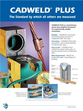

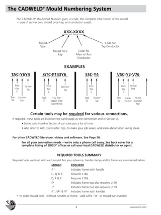


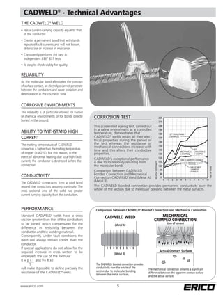
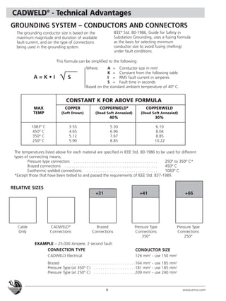


The document is a catalog for CADWELD welded electrical connections. It describes CADWELD PLUS as a revolutionary system that simplifies the process for exothermically welded connections. CADWELD connections perform best in independent tests and CADWELD PLUS offers easy ignition and flexibility. The catalog provides ordering information, technical details, and diagrams for a wide variety of connection types between cables, busbars, lugs, ground rods, and more.