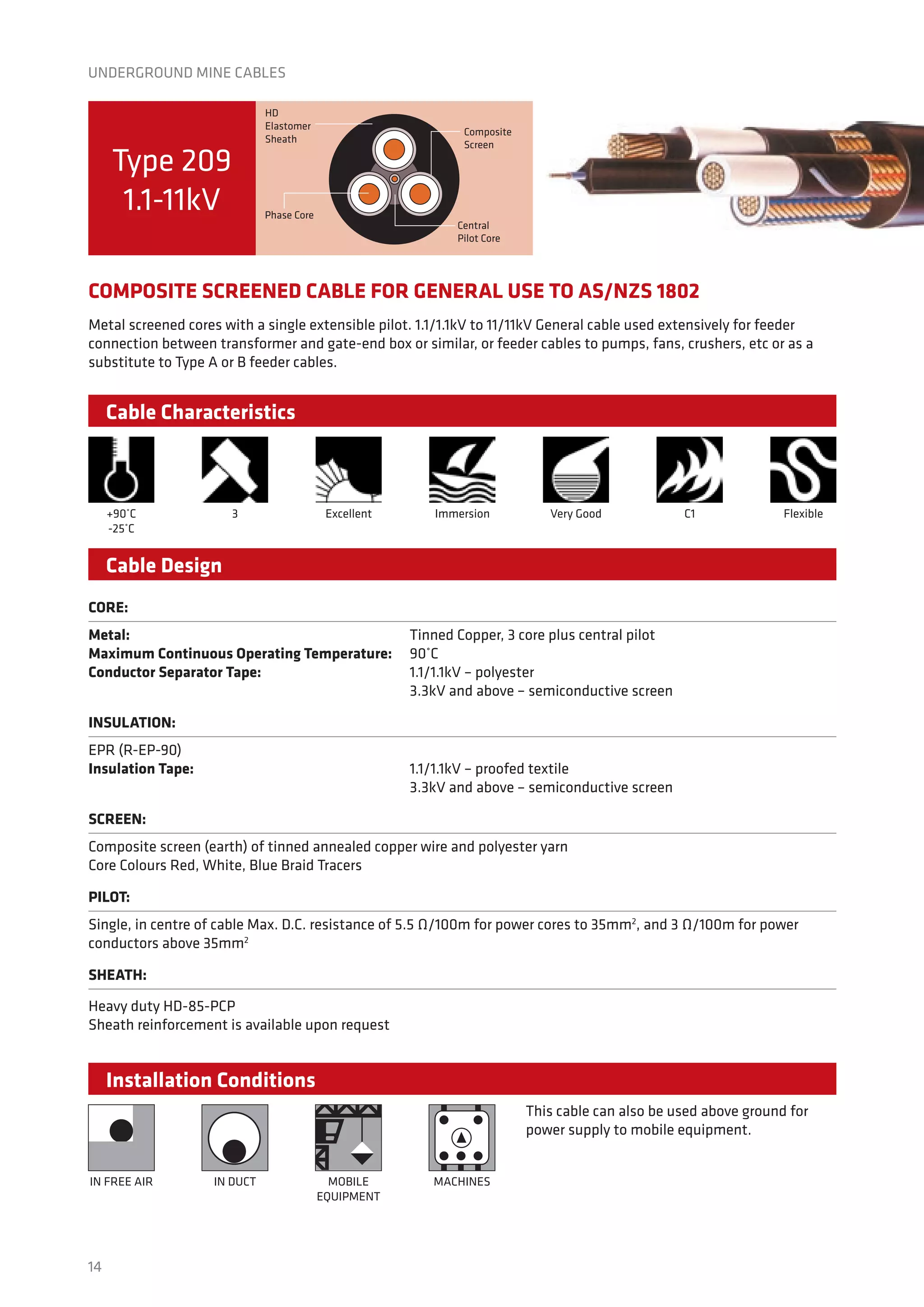
Prysmian manufactures composite screened cables for use in underground coal mines. The Type 209 cable is designed for general use in underground mines from 1.1-11kV in accordance with Australian standards. It has tinned copper conductors, EPR insulation, a composite screen, and a heavy duty PCP sheath. The cable is highly flexible and resistant to harsh and wet underground mining environments.
Modern underground power cables are sophisticated assemblies of insulators, conductors and protective materials. Within these components are sensors, which enable cable operators to monitor conditions along the cable in real time.
The condition of the cable insulation is usually monitored through the following two main methods:
Loss tangent measurements
Partial discharge (PD) measurements
A Presentation based on Underground Cables Used In the Transmission And Distribution System.It is a topic covered in the syllabus of B.E. in Electrical Engineering in 5th semester Subject named "Electrical Power System" For more detail you can check the book "Electrical Power System" by Author V.K.Mehta and S.Chand Publication.
Complete Description of High Quality Tempsens Make Instrumentation, Control, Signal and Mineral Insulated (MI) Cables and Wires
And Insulation offered on wires and cables.
These Cables and wires covers wide areas of applications in different types of process industries and OEMs.
Underground cables are used for power applications where it is impractical, difficult, or dangerous to use the overhead lines. They are widely used in densely populated urban areas, in factories, and even to supply power from the overhead posts to the consumer premises.
The underground cables have several advantages over the overhead lines; they have smaller voltage drops, low chances of developing faults and have low maintenance costs. However, they are more expensive to manufacture, and their cost may vary depending on the construction as well as the voltage rating.
The underground cables are classified in two ways; by the voltage capacity, or by the construction.
By Voltage
LT cables: Low-tension cables with a maximum capacity of 1000 V
HT Cables: High-tension cables with a maximum of 11KV
ST cables: Super-tension cables with a rating of between 22 KV and 33 KV
EHT cables: Extra high-tension cables with a rating of between 33 KV and 66 KV
Extra super voltage cables: with maximum voltage ratings beyond 132 KV
By Construction
Belted cables: Maximum voltage of 11KVA
Screened cables: Maximum voltage of 66 KVA
Pressure cables: the Maximum voltage of more than 66KVA
The outdoor silicone-rubber insulation design includes a skirt configuration that offers exceptional creep, strike, weather and contamination resistance, along with superior cable sealing and voltage withstand. All termination kits come complete with the housing and stress tube pre-assembled on the core, ready for quick and easy installation.
“The Ranger2® Shrink-Fit Terminations enhance the breadth of our Elastimold® line of pre-molded cable accessory components,” said Mike Jackson, Product Manager for Thomas & Betts. “Their design provides the superior skirt configurations for riser pole, pad-mounted and other installations exposed to the elements.”
The single-piece terminations for 15kV and 25kV applications feature shrink-fit design for effortless installation. The two-piece termination for 35kV applications facilitates easier core removal: one needs only to position the terminator on the prepared cable and remove the center core. The terminations are compact and lightweight to enable installations in restricted spaces and free-hanging applications.
Elastimold® Ranger2® Shrink-Fit Terminations 15-35kV meet or exceed all requirements of IEEE Standard 48 for Class 1 outdoor or Class 2 indoor terminations.
Since the loads having the trends towards growing density. This requires the better appearance, rugged construction, greater service reliability and increased safety. An underground cable essentially consists of one or more conductors covered with suitable insulation and surrounded by a protecting cover. The interference from external disturbances like storms, lightening, ice, trees etc. should be reduced to achieve trouble free service. The cables may be buried directly in the ground, or may be installed in ducts buried in the ground.
Epec Engineered Technologies manufactures custom cables for specific applications based upon customer design and print requirements. We can assist with cable and connector selection, layout and manufacturing techniques, and computer aided design (CAD).
We also provide short-run manufacturing prior to mass production along with all aspects of the manufacturing process, including soldering, termination, wrapping and testing. Through our very formal quality assurance and testing processes Epec ensures the quality of all manufactured products.
We are all should product our Defense and DRDO along with Make IN India Initiative .
JMV LPS Ltd Strongly Belive Make in India Offer Earthing ,Lightning and Surge Protect for Guard and Safe Guard all Electrical Equipment Installation (Temporary or Permanent) for Infrastructure ,Equipment's and other On board Mounted Defense Equipment's.
JMV LPS Ltd is having all Indian and International Standard approvals for all Manufacturing products.
We also having own Test Lab for Testing Electrical and Surge up 10/350Micro Sec.
Plz Call us for presentation or Sent inquiry.
Information Useful for
All Defense Engineering Departments E/M Navy , Air-force ,,Army Design ,Engineering and Production Unit Like BHEL,BEL,CEL ,BEML Tata Defense Products Div,Mahindra Defense Product Div, Honeywell Defense Project Div ,Reliance Defense Product Div,L&T Defense Product & Project Div,DRDO & Defense LAB's ,MES, Garrison Engineer's, System Integrator's ,Consultants,EPC Contractors.Ministry of Defense & Space Project's.
250um loose tube vs. 900um tight buffered fiberAngelina Li
Choosing the right fiber-optic cable has become more challenging than ever. Factors like the advent
of new cable designs, suppliers, changes in fiber specifications, and the many claims of cable
performance can confuse even the most seasoned network designers.
The Roxtec KFO frame is a lightweight composite (PA) frame, suitable where it is important to keep weight down to a minimum. An openable frame which can be installed around existing cables. It can be supplied with an 80 millimetre wide plastic flange (PP) for bolting to fragile structures where the holes need to be drilled at a distance from the frame. Available as a single opening frame, with or without flange. For use with RM Components.
Roxtec cable transit frames provide rectangular sealing frames for cables and pipes ensuring safety, efficiency and long-term operational reliability - Roxtec cable and pipe seals protect against fire, gas, water, dusts, pests, blast load and electromagnetic interference.
T&D UK can provide nationwide site surveys to assess your on-site requirement for Roxtec cable and pipe sealing transit frames. Roxtec sealing solutions for cables and pipes ensure safety, efficiency and long term operational reliability.
Fire Rated, LSOH (Low Smoke Zero Halogen LSF) Junction Box Enclosures IEC 331
(750°C for 3 hours) & BS6387 (950°C for 3 hours - Flame Only)
Fire Rated Electrical Enclosures - Mild, Stainless Steel, GRP
When installing essential electrical systems such as emergency lighting or fire safety controls, great emphasis is placed upon the fire survivability of the critical components such as fire dampers, actuators and cables that are contained in the area. Often the specification of the junction boxes and enclosures is neglected with respect to fire resistance and survival. On the basis that any system is only as good as the weakest part, it is important that attention is paid to the junction boxes being utilised for essential systems.
Abtech ensure the fire survival of junction boxes using both the SX (stainless steel enclosure) and BPG (GRP enclosure) ranges.
Fire Rated Electrical Enclosures Tested to IEC 331 - SX Enclosure Range :
IEC331 - 750 Degrees celsius for 3 hours - flame only - PASSED
BS6387 C - 950 Degrees celsius for 3 hours - flame only - PASSED
BS6387 Z - 950 Degrees celius for 3 hours - external impact - PASSED
BS6387 W - 950 Degrees celsius for 3 hours - water spray - PASSED
Abtech SX and BPG electrical enclosures and junction boxes when fitted with ceramic terminals are suitable for use in areas designated to require fire resistant cables according to IEC331, BS6387 C (fire alone), BS6387 Z (impact test) and BS6387 W (fire with water test).
Prysmian Draka supplies a complete range of marine, offshore oil and gas power, control and instrumentation cables for use on oil platforms and floating oil production units (FPSO). T&D distribute an extensive range of cables from 250V to 33kV - a complete range of marine, offshore oil and gas industry cables to IEEE, UKOOA and IEC specification.
The T&D and Prysmian commercial relationshipgoes back to the previous century. T&D have distributed the Prysmian Components range of cable joints, cable glands, cable cleats and high voltage cable terminations for several decades. The new relationship will now extend T&D's portfolio to embrace Prysmian Draka Offshore Marine, Oil & Gas cables.
Prysmian Draka Marine Offshore Oil & Gas Cables - Overview
RFOU(i) 250V S1/S5 Halogen-free, mud resistant instrumentation cable
RFOU(c)250V S2/S6 Halogen-free, mud resistant instrumentation cable
BFOU(i)250V S3/S7 Halogen-free, mud and fire resistant instrumentation cable
BFOU(c)250V S4/S8 Halogen-free, mud and fire resistant instrumentation cable
RU(i) 250V S11 Halogen-free, unarmoured, mud resistant instrumentation cable
BU(i) 250V S13 Halogen-free, unarmoured, mud resistant instrumentation cable
BU(c) 250V S14 Halogen-free, unarmoured, mud resistant instrumentation cable
RFOU 0,6/1kV P1/P8 Halogen-free, mud resistant power cable
RFOU 6/10(12)kV P3/P10 Halogen-free, mud resistant HV power cable
RFOU 12/20(24)kVP19/P21 Halogen-free, mud resistant HV power cable
BFOU 0,6/1kV P5/P12 Halogen-free, mud resistant, fire resistant power cable
UX 1000V P15 Halogen-free, mud resistant insulated conductor
RU 0,6/1kV P18 Halogen-free, unarmoured, mud resistant power cable
BU 0,6/1kV P17 Halogen-free, fire resistant, unarmoured, mud resistant power cable
QFCI Fire resistant optical fibre cable, halogen-free
AICI Optical cable for industrial environments
IFLI 250V P16 Cables for living quarter and office areas, halogen-free
Surge generator cable fault locators ("thumpers") provide pre-location and pinpoint cable fault location. Cable fault prelocation using ICE (Impulse Current Method) is preferred for extensive underground cable fault location and pinpointing cable faults in water damaged cable joints. Precise location of cable faults through surge generator fault locators (cable thumping) is very quick and limits expensive excavation by pinpoint accuracy.
DC testing has been accepted for many years as the standard field method for performing high-voltage tests on cable insulation systems. Whenever DC testing is performed, full consideration should be given to the fact that steady-state direct voltage creates within the insulation systems an electrical field determined by the geometry and conductance of the insulation, whereas under service conditions, alternating voltage creates an electric field determined chiefly by the geometry and dielectric constant (or capacitance) of the insulation.
Under ideal, homogeneously uniform insulation conditions, the mathematical formulas governing the steady-state stress distribution within the cable insulation are of the same form for DC and for AC, resulting incomparable relative values; however, should the cable insulation contain defects in which either the conductivity or the dielectric constant assume values significantly different from those in the bulk of the insulation,the electric stress distribution obtained with direct voltage will no longer correspond to that obtained with alternating voltage.
this ppt is base on construction of under ground cable. in this ppt i gave information the all type of insulation and its specification. and is advantages.
Underground transmission line:
The aim of this unit are to: Analyze the resistance,inductance and capacitance of underground transmission lines
t the end of this unit, you will be able to:
explain where Underground Cables are applicable and the Requirements of choosing underground cables in electrical networks
determine the values of C,L and R per unit length in underground electrical line
Select the right type of cable for a particular system based on the voltage to deliver
estimate the right parameters for a single core for a given transmission line
determine the current rating for a given network and also know how underground cables are installed
explain the method of testing, locating, confirming, and troubleshooting any fault in the underground cables for a given electrical network
Indicative resources:
Principles of power systems, by Mehta and Mehta
A_Textbook_of_Electrical_Technology_Volume_III
Electrical Power systems by Wadhwa
Power system Analysis by Weedy and Cory
Power system by Grainger and Stevenson
Fertilizer and Chemical Process Plant ,Food and Pharma , PDIL,EIL,Development Consultant India Pvt Ltd Tata Consulting Engineers;MECON;HURL,PLC and DCS Manufacturer /System Intergrators/EPC Companies Handling Electrical and C&I Projects.
Isolation Procedures for Safe Working on Electrical Systems and Equipment by the JIB | solation Procedures for Safe Working on Electrical Systems and Equipment
This chart shows the safe isolation procedure that you should use when working on electrical systems and equipment.
You'll receive a printed copy of this from your Training Provider, but it's also here as a handy reference to keep electronically.
THE RULES OF SAFE ISOLATION ARE:
Obtain permission to start work (a Permit may be required in some situations)
Identify the source(s) of supply using an approved voltage indicator or test lamp
Prove that the approved voltage indicator or test lamp is functioning correctly
Isolate the supply(s)
Secure the isolation
Prove the system/equipment is DEAD using an approved voltage indicator or test lamp
Prove that the approved voltage indicator or test lamp is functioning correctly
Put up warning signs to tell other people that the electrical installation has been isolated
Once the system/equipment is proved DEAD, work can begin
Uploaded by THORNE & DERRICK LV HV Jointing, Earthing, Substation & Electrical Eqpt | Explosive Atmosphere Experts & ATEX IECEx.
THORNE & DERRICK based in the UK are international distributors of LV, MV & HV Cable Installation, Jointing, Substation & Electrical Equipment.
Since 1985, T&D have established an international reputation based on SERVICE | INTEGRITY | TRUST.
Contact us for 3M, ABB, Alroc, AN Wallis, CATU, Cembre, Centriforce, CMP, CSD, Elastimold, Ellis Patents, Emtelle, Euromold, Filoform , Furse, Lucy Electric & Zodion, Nexans, Pfisterer, Polypipe, Prysmian, Roxtec, Sicame, WT Henley.
Essentials of Automations: Optimizing FME Workflows with ParametersSafe Software
Are you looking to streamline your workflows and boost your projects’ efficiency? Do you find yourself searching for ways to add flexibility and control over your FME workflows? If so, you’re in the right place.
Join us for an insightful dive into the world of FME parameters, a critical element in optimizing workflow efficiency. This webinar marks the beginning of our three-part “Essentials of Automation” series. This first webinar is designed to equip you with the knowledge and skills to utilize parameters effectively: enhancing the flexibility, maintainability, and user control of your FME projects.
Here’s what you’ll gain:
- Essentials of FME Parameters: Understand the pivotal role of parameters, including Reader/Writer, Transformer, User, and FME Flow categories. Discover how they are the key to unlocking automation and optimization within your workflows.
- Practical Applications in FME Form: Delve into key user parameter types including choice, connections, and file URLs. Allow users to control how a workflow runs, making your workflows more reusable. Learn to import values and deliver the best user experience for your workflows while enhancing accuracy.
- Optimization Strategies in FME Flow: Explore the creation and strategic deployment of parameters in FME Flow, including the use of deployment and geometry parameters, to maximize workflow efficiency.
- Pro Tips for Success: Gain insights on parameterizing connections and leveraging new features like Conditional Visibility for clarity and simplicity.
We’ll wrap up with a glimpse into future webinars, followed by a Q&A session to address your specific questions surrounding this topic.
Don’t miss this opportunity to elevate your FME expertise and drive your projects to new heights of efficiency.
Transcript: Selling digital books in 2024: Insights from industry leaders - T...BookNet Canada
The publishing industry has been selling digital audiobooks and ebooks for over a decade and has found its groove. What’s changed? What has stayed the same? Where do we go from here? Join a group of leading sales peers from across the industry for a conversation about the lessons learned since the popularization of digital books, best practices, digital book supply chain management, and more.
Link to video recording: https://bnctechforum.ca/sessions/selling-digital-books-in-2024-insights-from-industry-leaders/
Presented by BookNet Canada on May 28, 2024, with support from the Department of Canadian Heritage.
Encryption in Microsoft 365 - ExpertsLive Netherlands 2024Albert Hoitingh
In this session I delve into the encryption technology used in Microsoft 365 and Microsoft Purview. Including the concepts of Customer Key and Double Key Encryption.
State of ICS and IoT Cyber Threat Landscape Report 2024 previewPrayukth K V
The IoT and OT threat landscape report has been prepared by the Threat Research Team at Sectrio using data from Sectrio, cyber threat intelligence farming facilities spread across over 85 cities around the world. In addition, Sectrio also runs AI-based advanced threat and payload engagement facilities that serve as sinks to attract and engage sophisticated threat actors, and newer malware including new variants and latent threats that are at an earlier stage of development.
The latest edition of the OT/ICS and IoT security Threat Landscape Report 2024 also covers:
State of global ICS asset and network exposure
Sectoral targets and attacks as well as the cost of ransom
Global APT activity, AI usage, actor and tactic profiles, and implications
Rise in volumes of AI-powered cyberattacks
Major cyber events in 2024
Malware and malicious payload trends
Cyberattack types and targets
Vulnerability exploit attempts on CVEs
Attacks on counties – USA
Expansion of bot farms – how, where, and why
In-depth analysis of the cyber threat landscape across North America, South America, Europe, APAC, and the Middle East
Why are attacks on smart factories rising?
Cyber risk predictions
Axis of attacks – Europe
Systemic attacks in the Middle East
Download the full report from here:
https://sectrio.com/resources/ot-threat-landscape-reports/sectrio-releases-ot-ics-and-iot-security-threat-landscape-report-2024/
Slack (or Teams) Automation for Bonterra Impact Management (fka Social Soluti...Jeffrey Haguewood
Sidekick Solutions uses Bonterra Impact Management (fka Social Solutions Apricot) and automation solutions to integrate data for business workflows.
We believe integration and automation are essential to user experience and the promise of efficient work through technology. Automation is the critical ingredient to realizing that full vision. We develop integration products and services for Bonterra Case Management software to support the deployment of automations for a variety of use cases.
This video focuses on the notifications, alerts, and approval requests using Slack for Bonterra Impact Management. The solutions covered in this webinar can also be deployed for Microsoft Teams.
Interested in deploying notification automations for Bonterra Impact Management? Contact us at sales@sidekicksolutionsllc.com to discuss next steps.
Elevating Tactical DDD Patterns Through Object CalisthenicsDorra BARTAGUIZ
After immersing yourself in the blue book and its red counterpart, attending DDD-focused conferences, and applying tactical patterns, you're left with a crucial question: How do I ensure my design is effective? Tactical patterns within Domain-Driven Design (DDD) serve as guiding principles for creating clear and manageable domain models. However, achieving success with these patterns requires additional guidance. Interestingly, we've observed that a set of constraints initially designed for training purposes remarkably aligns with effective pattern implementation, offering a more ‘mechanical’ approach. Let's explore together how Object Calisthenics can elevate the design of your tactical DDD patterns, offering concrete help for those venturing into DDD for the first time!
Epistemic Interaction - tuning interfaces to provide information for AI supportAlan Dix
Paper presented at SYNERGY workshop at AVI 2024, Genoa, Italy. 3rd June 2024
https://alandix.com/academic/papers/synergy2024-epistemic/
As machine learning integrates deeper into human-computer interactions, the concept of epistemic interaction emerges, aiming to refine these interactions to enhance system adaptability. This approach encourages minor, intentional adjustments in user behaviour to enrich the data available for system learning. This paper introduces epistemic interaction within the context of human-system communication, illustrating how deliberate interaction design can improve system understanding and adaptation. Through concrete examples, we demonstrate the potential of epistemic interaction to significantly advance human-computer interaction by leveraging intuitive human communication strategies to inform system design and functionality, offering a novel pathway for enriching user-system engagements.
Generating a custom Ruby SDK for your web service or Rails API using Smithyg2nightmarescribd
Have you ever wanted a Ruby client API to communicate with your web service? Smithy is a protocol-agnostic language for defining services and SDKs. Smithy Ruby is an implementation of Smithy that generates a Ruby SDK using a Smithy model. In this talk, we will explore Smithy and Smithy Ruby to learn how to generate custom feature-rich SDKs that can communicate with any web service, such as a Rails JSON API.
GraphRAG is All You need? LLM & Knowledge GraphGuy Korland
Guy Korland, CEO and Co-founder of FalkorDB, will review two articles on the integration of language models with knowledge graphs.
1. Unifying Large Language Models and Knowledge Graphs: A Roadmap.
https://arxiv.org/abs/2306.08302
2. Microsoft Research's GraphRAG paper and a review paper on various uses of knowledge graphs:
https://www.microsoft.com/en-us/research/blog/graphrag-unlocking-llm-discovery-on-narrative-private-data/
Neuro-symbolic is not enough, we need neuro-*semantic*Frank van Harmelen
Neuro-symbolic (NeSy) AI is on the rise. However, simply machine learning on just any symbolic structure is not sufficient to really harvest the gains of NeSy. These will only be gained when the symbolic structures have an actual semantics. I give an operational definition of semantics as “predictable inference”.
All of this illustrated with link prediction over knowledge graphs, but the argument is general.
Smart TV Buyer Insights Survey 2024 by 91mobiles.pdf91mobiles
91mobiles recently conducted a Smart TV Buyer Insights Survey in which we asked over 3,000 respondents about the TV they own, aspects they look at on a new TV, and their TV buying preferences.
JMeter webinar - integration with InfluxDB and GrafanaRTTS
Watch this recorded webinar about real-time monitoring of application performance. See how to integrate Apache JMeter, the open-source leader in performance testing, with InfluxDB, the open-source time-series database, and Grafana, the open-source analytics and visualization application.
In this webinar, we will review the benefits of leveraging InfluxDB and Grafana when executing load tests and demonstrate how these tools are used to visualize performance metrics.
Length: 30 minutes
Session Overview
-------------------------------------------
During this webinar, we will cover the following topics while demonstrating the integrations of JMeter, InfluxDB and Grafana:
- What out-of-the-box solutions are available for real-time monitoring JMeter tests?
- What are the benefits of integrating InfluxDB and Grafana into the load testing stack?
- Which features are provided by Grafana?
- Demonstration of InfluxDB and Grafana using a practice web application
To view the webinar recording, go to:
https://www.rttsweb.com/jmeter-integration-webinar
LF Energy Webinar: Electrical Grid Modelling and Simulation Through PowSyBl -...DanBrown980551
Do you want to learn how to model and simulate an electrical network from scratch in under an hour?
Then welcome to this PowSyBl workshop, hosted by Rte, the French Transmission System Operator (TSO)!
During the webinar, you will discover the PowSyBl ecosystem as well as handle and study an electrical network through an interactive Python notebook.
PowSyBl is an open source project hosted by LF Energy, which offers a comprehensive set of features for electrical grid modelling and simulation. Among other advanced features, PowSyBl provides:
- A fully editable and extendable library for grid component modelling;
- Visualization tools to display your network;
- Grid simulation tools, such as power flows, security analyses (with or without remedial actions) and sensitivity analyses;
The framework is mostly written in Java, with a Python binding so that Python developers can access PowSyBl functionalities as well.
What you will learn during the webinar:
- For beginners: discover PowSyBl's functionalities through a quick general presentation and the notebook, without needing any expert coding skills;
- For advanced developers: master the skills to efficiently apply PowSyBl functionalities to your real-world scenarios.
2. 3
Introduction
ONE LEADER, TWO BRANDS
The world’s largest cable company, the Prysmian
Group, consists of Prysmian and Draka which are two
of the world’s most respected commercial brands in
the industry. With subsidiaries in 50 countries, almost
100 manufacturing plants, 17 Research & Development
Centres and around 22,000 employees, the Prysmian
Group is truly a global company.
Proudly manufacturing in Australia since 1940, Prysmian
understands local standards and conditions and our
products are designed and developed accordingly.
Prysmian specialises in integrated, added value
cabling solutions highly customised to the individual
specifications of customers. Prysmian operates a
Quality Management System compliant with the
requirements of ISO 9001:2008 and products are fully
supported by the global technical and production
capabilities of the Prysmian Group.
Prysmian understands local
standards and conditions and
our products are designed and
developed accordingly.
3. 4
Development of elastomeric power cables
for safe and reliable mining and industrial
applications has paralleled the development
of the electric motor and power generation
since the 19th century.
Elastomeric cables are the natural choice for
applications where durability, flexibility, and safe
operation under extreme environmental conditions are
important. The Prysmian Group’s elastomeric cables
have been “field proven” in thousands of operations,
and with continuous development, utilise the best
features of cables offered around the world.
In Australia, as elsewhere, there are many established
guidelines governing manufacture of mining and
industrial cables. Innovation in work practices, with
more equipment operating at higher voltages, has
required the continued development of new elastomeric
cable designs. Ongoing development programs have
also been required to continually improve the reliability
and safety of current designs. The major design
responsibility for the Prysmian Group is to ensure that
cables supplied will operate reliably and safely under a
wide range of conditions. Personnel often work close to
energised cables, especially in underground mines. The
cable construction and materials must be selected to
provide maximum safety during both normal operation
and in the case of cable failure.
CONDUCTORS
The important flexibility, strength and electrical
properties of mining and industrial cables are mainly
derived from the particular conductor design used,
and any armouring or reinforcement. Conductors used
in these cables are to Australian and International
Standards, and usually employ tinned annealed copper
wires stranded to provide optimum flexibility. Flexibility
is influenced by the number of individual wires for a
given size, the lay length of bunches and strands, and
the geometric arrangement of the strands.
Cable Components
4. 5
A simple examination of wires and their size is not a
reliable guide to their flexibility or endurance, since
special designs are often developed to suit particular
applications. These would include cables for heavy-duty
reeling or flexing such as ship-loader or longwall shearer
applications. The use of specially designed power, earth
or pilot conductors, and their locations in the cable
provide a good example of this.
CORE ASSEMBLY LAY LENGTH
This is a vital factor affecting cable life when the cable is
subjected to repeated reeling, especially under tension.
A ratio of cable lay length (pitch) to pitch circle diameter
(the diameter of a circle passing through the mid points
of the cores) is commonly used to specify lay lengths
suited to various applications. For moderate duty reeling
cables, this value should be less than 12.5, and for
trailing cables it should be less than 17.
CABLE COMPONENTS
5. 6
CABLE COMPONENTS
INSULATION
In the past fifty years, natural rubber insulation has
been replaced by synthetic polymeric compounds with
inherently superior properties. Ethylene-propylene
copolymer (EPR) and terpolymer (EPDM) are most
common on flexible cables, offering excellent
thermal durability, corona resistance, and electrical
characteristics. Cross linked polyethylene (XLPE)
insulation has found limited use in fixed applications.
Insulation materials are chosen for optimum dielectric
characteristics, and resistance to deterioration through
heat, oxidation, salts and copper compounds. Inert
fillers are used for maximum electrical stability and low
moisture absorption.
PILOT
The resistance between mining equipment and earth
is usually high, and dangerous voltages can be present.
To prevent hazards from shock, ground fault currents
are controlled by various systems, including neutral
resistance grounding. To ensure the integrity of this
safety circuit, a small independent current may be
passed through a pilot conductor to the load centre and
return through the earth conductor. If this current is
interrupted through breakage, then the circuit breaker
will automatically trip and remove power from the cable.
Australian mining regulatory authorities require the
inclusion of an extensible central pilot conductor (for
monitoring circuit integrity). This is specially designed
and manufactured to restrict extensibility in service. The
cores of each underground coal mining cable must also
be electrically symmetrical for added safety.
SCREENS
Bending of conductors under tension accelerates
the breakage of individual wires. Partial failure of
conductors can lead to wire ends that penetrate through
the insulation. Metallic screens over the power cores, or
earthing cores associated with semiconductive rubber
components are provided to ground such faults through
an earth. Besides being part of the earth fault detection
circuit, screens relieve non-uniform electrical stresses
and provide a uniform capacitance to ground.
6. 7
CABLE COMPONENTS
Screening is achieved by either a helically applied layer
of wires, a composite textile and tinned copper wire
braid, semi-conductive elastomer, or a combination of
the latter. Medium voltage reeling and trailing cables
usually have either individually core composite textile
/ copper braid or semiconductive rubber screens for
minimal fatigue failure. Collective screens of either
semiconductive rubber, braids, or pliable steel wire
armour with copper wires to achieve the desired
conductivity may also be used. The latter types are
used in cable constructions for fixed or feeder cable
applications.
Semiconductive rubber screens are used in cables
connected to systems which are able to limit earth
faults to around 500 mA (r.m.s.) within about 10ms.
Australian cables have fire propagation resistant
semiconductive screens.
ARMOUR & REINFORCEMENT
Prysmian Group trailing cables manufactured to AS/NZS
1802 and AS/NZS 2802 and subjected to harsh wear,
employ nylon textile or woven polyester tape, or an open
braid of Kevlar® fibre as reinforcement. This enhances
the sheath’s mechanical strength, and improves the
resistance against damage from crushing, stretching,
and tear propagation.
Where a very high degree of impact and cut resistance is
required, designs will usually have a pliable wire armour.
This makes the cable much heavier and more difficult
to handle and use. Heavy duty textile reinforcement is
preferred form an operational point of view.
SHEATH
The primary role of the cable sheath is to protect the
underlying core assembly from mechanical, chemical,
or other environmental damage. Polychloroprene (PCP),
chlorosulphonated polyethylene (CSP), and chlorinated
polyethylene (CPE) are the most commonly used
synthetic polymers used in sheaths today. They are
commonly filled with other materials to enhance sheath
performance.
A properly formulated sheathing compound is essential
for a high performance reeling or trailing cable. The
higher the tensile strength, the stronger the material
is when stretched. As the material gets hotter, tensile
strength reduces with a consequent reduction in tear
resistance. As cables age, elongation may be reduced
(the material becomes brittle).
7. 8
Cable Handling
MINIMUM BENDING
RADIUS DURING
INSTALLATION
MINIMUM
INSTALLATION
TEMPERATURE
INTERNAL
WIRING
IN FREE AIR
INDUSTRIAL
EQUIPMENT
IN GROUND WITH
PROTECTION
EXTERNAL
BUILDING
IN TRENCH IN GROUND IN DUCT DOMESTIC
APPLIANCES
MACHINES
MOBILE
EQUIPMENT
IN CONDUIT
SUBMERGED
OUTDOOR
APPLIANCES
OVERHEAD AERIAL
FESTOON
AMBIENT TEMPERATURE
Maximum continuous conductor temperature
Minimum continuous conductor temperature
HALOGEN FREE
Halogen free (toxic fume or corrosives) cables
MINIMUM BENDING RADIUS
Minimum bending radius of installed cables
MECHANICAL IMPACT RESISTANCE
1 Light Impact
2 Moderate Impact
3 Heavy Impact
4 Very Heavy Impact
RESISTANCE TO SOLAR RADIATION AND WEATHER
Excellent Permanent
Very Good Frequent
Good Occasional
Acceptable Accidental
Poor None
FLEXIBILITY
Rigid Flexible
Semi-rigid Semi flexible
Very flexible
CHEMICAL RESISTANCE
Excellent Permanent
Very Good Frequent
Good Occasional
Acceptable Accidental
Poor None
BEHAVIOUR IN FLAME AND FIRE
Reaction To Fire Resistant To Fire
C 1 Fire retardant CR 1 Fire resistant
C 2 Flame retardant CR 2 All non CR 1 cables
C 3 No fire performance
RESISTANCE TO WATER
Negligible No humidity
Water Drops Occasional condensation
Spray Water run off
Splashes Exposed to water splashes
Heavy Sea Exposed to waves
Immersion Temporarily covered by water
Submersion Permanently covered by water
Cable Usage Characteristics
Laying Conditions
8. 9
People are our greatest asset. We believe
everyone has the right to work and live in a
healthy and safe environment.
The Prysmian Group maintains our commitment to
comply with all relevant Occupational Health, Safety and
Environmental legislation, Australian and New Zealand
Standards (AS/NZS 4801 and ISO 14001) Licences and
Industry Codes of Practices.
Our goal is an environmentally and socially sustainable
business and we believe that a safe work environment
is a sign of efficiency and quality. Accidents can be
prevented and we commit to continually improve, to
achieve zero incidents of work related injury, illness and
environmental pollution.
We also aim to help our customers fulfil their
environmental responsibilities by providing them with
cables and associated products that we believe have
been manufactured as efficiently, economically sound
and environmentally sustainable as possible. As our
products are locally designed and manufactured we
recognize the importance of risk assessment and
mitigation in all mining operations.
For additional support in this area we have dedicated
technical staff available to provide specific product
information and guidelines for use please contact:
sales.au@prysmiangroup.com
Health, Safety and Environment
9. “Electric cables in underground coal mine hazardous
zones are subject to an extremely arduous environment
that is often very wet. In addition, they are handled
regularly by mine workers while energised.”
- NSW Government Industry & Investment. Technical Report EES-100.
Electrical Engineering Safety Underground Coal Mine. Electric Cables used in Hazardous Zones
10. Underground Mine Cables
A
ustralian and New Zealand coal mines are some of the safest in the world. This safety record is built on strict
controls and legislation to ensure that the cables for mining equipment and in particularly those used in
hazardous areas are of particularly high quality.
Our cables listed in this section are compliant with the relevant standards for the differently classified zones of an
underground mine, including AS/NZS 1802, AS/NZS 1972 and AS/NZS 5000.1. Prysmian cables manufactured to
these standards have a proven track record of safe and reliable performance in the harsh environments that exist in
underground mines.
We understand that a longwall mining operation may have very different demands on cable performance to a board
and pillar or hydraulic monitor operation and our range is tailored to suit the specific challenges that varied mining
operations present.
11. 14
Type 209
1.1-11kV
COMPOSITE SCREENED CABLE FOR GENERAL USE TO AS/NZS 1802
Metal screened cores with a single extensible pilot. 1.1/1.1kV to 11/11kV General cable used extensively for feeder
connection between transformer and gate-end box or similar, or feeder cables to pumps, fans, crushers, etc or as a
substitute to Type A or B feeder cables.
This cable can also be used above ground for
power supply to mobile equipment.
Cable Characteristics
Installation Conditions
Cable Design
Core:
Metal: Tinned Copper, 3 core plus central pilot
Maximum Continuous Operating Temperature: 90˚C
Conductor Separator Tape: 1.1/1.1kV – polyester
3.3kV and above – semiconductive screen
INSULATION:
EPR (R-EP-90)
Insulation Tape: 1.1/1.1kV – proofed textile
3.3kV and above – semiconductive screen
SCREEN:
Composite screen (earth) of tinned annealed copper wire and polyester yarn
Core Colours Red, White, Blue Braid Tracers
PILOT:
Single, in centre of cable Max. D.C. resistance of 5.5 Ω/100m for power cores to 35mm2
, and 3 Ω/100m for power
conductors above 35mm2
SHEATH:
Heavy duty HD-85-PCP
Sheath reinforcement is available upon request
+90˚C
-25˚C
3 Excellent Immersion Very Good C1 Flexible
IN FREE AIR IN DUCT MOBILE
EQUIPMENT
MACHINES
UNDERGROUND MINE CABLES
Central
Pilot Core
HD
Elastomer
Sheath
Composite
Screen
Phase Core
13. 16
Cable Characteristics
Installation Conditions
Cable Design
Core:
Metal: Tinned Copper, 3 core plus central pilot
Maximum Continuous Operating Temperature: 90˚C
INSULATION:
EPR (R-EP-90)
SCREEN:
Composite screen (earth) of tinned annealed copper wire and polyester yarn
Core Colours Red, White, Blue Braid Tracers
PILOT:
Single, in centre of cable
Pilot resistance is ≤ 5.5 Ω/100m
SHEATH:
Heavy Duty HD-85-PCP
+90˚C
-25˚C
3 Excellent Immersion Very Good C1
IN FREE AIR IN DUCT
COMPOSITE SCREENED CABLE FOR HAND-HELD EQUIPMENT TO AS/NZS 1802
Metal screened power cores and single extensible pilot. 1.1/1.1kV Cable used primarily for hand-held boring machines,
and as a flexible lead to other equipment where heavy duty service is required. Note, certain regulatory authorities
limit the use of this cable to 250/250V.
MACHINES
Flexible
Type 210
1.1kV
UNDERGROUND MINE CABLES
Central
Pilot Core
HD
Elastomer
Sheath
Composite
Screen
Phase Core
14. 17
Physical & Electrical Characteristics
Type 210
1.1kV
Power Conductor Screen Cable
Voltage
Rating
& Part
Number
Nominal
Area
Nominal
Diameter
Insulation
Thickness
ac
Resistance
@ 90°C &
50Hz
Reactance
@ 50Hz
3 Phase
Voltage
Drop
@ 90°C
& 50Hz
Capacitance
to Earth
Approx
Area
Sheath
Thickness
Nominal
Diameter
Approx
Mass
mm² mm mm Ω/km Ω/km mV/A.m
μF/phase/
km
mm²/
phase
mm mm kg/100m
Type 210.1
1.5-210-1 1.5 1.6 1.4 17.5 0.187 30.3 0.165 6.2 3.0 25.6 100
2.5-210-1 2.5 2.1 1.5 10.5 0.174 18.2 0.184 6.9 3.0 26.8 110
15. 18
Cable Characteristics
Installation Conditions
Cable Design
Core:
Metal: Tinned Copper, 3 core plus 3 pilots
Maximum Continuous Operating Temperature: 90˚C
Conductor Separator Tape: 1.1/1.1kV – polyester
3.3kV and above – semiconductive screen
INSULATION:
EPR (R-EP-90)
Insulation Tape: 1.1/1.1kV proofed textile
3.3kV and above, semiconductive screen
SCREEN:
Composite screen (earth) of tinned annealed copper wire and polyester yarn
Core Colours Red, White, Blue Braid Tracers
PILOT:
Three in the interstitial cavities
Elastomer covered and proofed taped
SHEATH:
Heavy Duty HD-85-PCP
On request the cable can be provided with a reinforced sheath
COMPOSITE SCREENED CABLE FOR GENERAL USE TO AS/NZS 1802
Metal screened power cores and three separate pilot conductors. 1.1/1.1kV to 11/11kV Cable used extensively for feeder
connection between transformer and gate-end box or similar, continuous miner cable or feeder cables to pumps.
Having three pilots, the cable can be used in long runs, without compromising pilot control protection system
resistance limitations.
Type 240
1.1-11kV
+90˚C
-25˚C
3 Excellent Immersion Very Good C1 Flexible
For applications requiring high degrees of
flexibility, Type 241 cables (semiconductive
screened) would be more appropriate.
IN FREE AIR IN DUCT MOBILE
EQUIPMENT
MACHINES
UNDERGROUND MINE CABLES
Pilot Core
HD
Elastomer
Sheath
Composite
Screen
Phase Core
17. 20
UNDERGROUND MINE CABLES
Type 241
1.1-11kV
Semiconductive screened cable for general use to AS/NZS 1802
Semiconductive screened power cores, with three earth cores and one extensible pilot. 1.1/1.1kV to 11/11kV General
purpose cable used for continuous miners, or feeder cables to pumps. Also commonly used for monorails supplying
DCBs and longwalls. Typically, a more flexible cable for use is a semiconductive screen instead of a metal screen.
Cable Characteristics
Installation Conditions
Cable Design
Core:
Metal: Tinned Copper, 3 core 3 earths plus central pilot
Flexibility: Flexible
Maximum Continuous Operating Temperature: 90˚C
Conductor Separator Type: 1.1/1.1kV - polyester where necessary
3.3kV and above - semiconductive screen
INSULATION:
EPR (R-EP-90) core with durably printed core numbers at intervals less than 300mm, on black semiconductive
insulation screen for phase identification
SCREEN:
Semiconductive elastomer screen
PILOT:
Single, in centre of cable. Max. D.C. resistance of 5.5 Ω/100m for power cores to 35mm2
, and 3 Ω/100m for power
conductors above 35mm2
EARTH:
Three semiconductive elastomer covered flexible earths, located in the interstices
SHEATH:
Open weave reinforcement, under heavy duty HD-85-PCP
IN FREE AIR IN DUCT MOBILE
EQUIPMENT
MACHINES
Central
Pilot Core
Semi
conductive
Elastomer
Screen
HD
Elastomer
Sheath
Earth Core
Numbered
Phase Core
+90˚C
-25˚C
3 Excellent Immersion Very Good C1 Flexible
19. 22
Semiconductive screened cable for general use to AS/NZS 1802
These cables have been designed to operate within the tight bending radii experienced with cable chains used on
longwall shearers, and provide additional pilot conductors for modern machine monitoring.
Semiconductive screened power cores, with three earth cones and one extensible pilot. General purpose cable for
continuous miners, or feeder cables to pumps. Also commonly used for monorails supplying DCBs and longwalls. Type
“PCD” 241SF cable has special lay-up. PCD ratio to provide maximum flexibility in arduous conditions.
Type 241SF cable designed for applications
requiring maximum flexibility.
Cable Characteristics
Installation Conditions
Cable Design
Core:
Metal: Tinned Copper, 3 core 3 earths plus central pilot
Flexibility: Very flexible for Type 241SF cable
Maximum Continuous Operating Temperature: 90˚C
Conductor Separator Type: 1.1/1.1kV - polyester where necessary
3.3kV and above - semiconductive screen
INSULATION:
EPR (R-EP-90) core with durably printed core numbers at intervals less than 300mm, on black semiconductive
insulation screen for phase identification
SCREEN:
Semiconductive elastomer screen
PILOT:
Single, in centre of cable. Max. D.C. resistance of 5.5 Ω/100m for power cores to 35mm2
, and 3 Ω/100m for power
conductors above 35mm2
EARTH:
Three semiconductive elastomer covered flexible earths, located in the interstices
SHEATH:
Open weave reinforcement, under heavy duty HD-85-PCP
IN FREE AIR IN DUCT MOBILE
EQUIPMENT
MACHINES
Central
Pilot Core
Semi
conductive
Elastomer
Screen
HD
Elastomer
Sheath
Earth Core
Numbered
Phase Core
Type 241SF
1.1-11kV
UNDERGROUND MINE CABLES
+90˚C
-25˚C
3 Excellent Immersion Very Good C1 V Flexible
20. 23
Physical & Electrical Characteristics
Type 241SF
1.1-11kV
Power Conductor Earth Cable
Voltage
Rating &
Part Number
Nominal
Area
Nominal
Diameter
Insulation
Thickness
ac
Resistance
@ 90°C &
50Hz
Reactance
@ 50Hz
3 Phase
Voltage
Drop
@ 90°C
& 50Hz
Capacitance
to Earth
Approx
Area
(each)
Sheath
Thickness
Nominal
Diameter
Approx
Mass
mm² mm mm Ω/km Ω/km mV/A.m
μF/phase/
km
mm² mm mm kg/100m
Type 241.1 SF
70-241-1 SF 70 12.1 1.8 0.346 0.0985 0.623 0.619 12.5 5.3 52.7 525
95-241-1 SF 95 13.6 2.0 0.271 0.0968 0.498 0.622 12.5 5.8 57.6 635
120-241-1 SF 120 15.6 2.1 0.210 0.0938 0.398 0.673 13.75 6.3 63.6 785
150-241-1 SF 150 17.5 2.3 0.166 0.0922 0.329 0.685 17 6.7 69.2 955
185-241-1 SF 185 19.0 2.5 0.137 0.0898 0.284 0.674 22 7.3 74.8 1115
240-241-1 SF 240 21.9 2.8 0.107 0.0881 0.240 0.689 27 8.0 83.7 1405
300-241-1 SF 300 24.4 3.0 0.0851 0.0862 0.210 0.736 35.7 8.7 91.2 1715
Type 241.3 SF
70-241-3 SF 70 12.1 3.0 0.346 0.107 0.627 0.422 12.5 6.4 60.9 635
95-241-3 SF 95 13.6 3.0 0.271 0.103 0.502 0.461 16 6.8 64.8 750
120-241-3 SF 120 15.6 3.0 0.210 0.0991 0.402 0.517 20 7.2 70.0 900
150-241-3 SF 150 17.5 3.0 0.166 0.0961 0.332 0.568 27 7.6 74.8 1075
185-241-3 SF 185 19.0 3.0 0.137 0.0924 0.286 0.600 35.2 8.0 78.9 1225
240-241-3 SF 240 21.9 3.0 0.107 0.0891 0.241 0.675 39.5 8.6 86.2 1485
300-241-3 SF 300 24.4 3.0 0.0851 0.0867 0.210 0.744 50 9.1 92.7 1775
Type 241.6 SF
70-241-6 SF 70 12.1 5.0 0.346 0.118 0.633 0.283 12.5 7.4 72.0 820
95-241-6 SF 95 13.6 5.0 0.271 0.114 0.509 0.307 16 7.9 76.1 945
120-241-6 SF 120 15.6 5.0 0.210 0.109 0.410 0.341 20 8.3 81.3 1110
150-241-6 SF 150 17.5 5.0 0.166 0.105 0.340 0.371 27 8.6 85.8 1290
185-241-6 SF 185 19.0 5.0 0.137 0.101 0.295 0.390 35.2 9.0 89.9 1445
240-241-6 SF 240 21.9 5.0 0.106 0.0971 0.249 0.436 39.5 9.6 97.2 1725
300-241-6 SF 300 24.4 5.0 0.0847 0.0941 0.219 0.478 50 10.2 104 2040
Type 241.11 SF
70-241-11 SF 70 12.1 7.6 0.346 0.129 0.640 0.212 12.5 8.9 86.4 1090
95-241-11 SF 95 13.6 7.6 0.271 0.125 0.517 0.229 16 9.3 90.3 1225
120-241-11 SF 120 15.6 7.6 0.210 0.119 0.418 0.252 20 9.7 95.5 1405
150-241-11 SF 150 17.5 7.6 0.165 0.115 0.348 0.273 27 10.0 100.0 1600
185-241-11 SF 185 19.0 7.6 0.136 0.110 0.303 0.286 35.2 10.4 104 1765
240-241-11 SF 240 21.9 7.6 0.106 0.106 0.260 0.317 39.5 11.0 111 2080
21. 24
Type 245UF
1.1-3.3kV
Ultra flexible cable for general use to AS/NZS 1802
These cables have been designed to operate within the tight bending radii experienced with cable chains used on
longwall shearers, and provide additional pilot conductors for modern machine monitoring.
Semiconductive screened power cores, with three earth cores and three extensible pilots for general purpose, and
especially for trailing applications in cable chains on Longwall Shearer equipment, and in environments calling for
maximum flexibility.
Cables designed for applications requiring
maximum flexibility.
Cable Characteristics
Installation Conditions
Cable Design
Core:
Metal: Tinned Copper, 3 core 3 earths plus 3 central pilots
Flexibility: Very flexible
Maximum Continuous Operating Temperature: 90˚C
Conductor Separator Type: 3.3kV - semiconductive screen
INSULATION:
EPR (R-EP-90) core with durably printed core numbers at intervals less than 300mm, on black semiconductive
insulation screen for phase identification
SCREEN:
Semiconductive elastomer screen
PILOT:
3 pilots, in the centre of the cable. Max. D.C. resistance of 3 Ω/100m for all cables
EARTH:
Three semiconductive elastomer covered flexible earths, located in the interstices
SHEATH:
Open weave reinforcement, under heavy duty HD-85-PCP
+90˚C
-25˚C
IN FREE AIR IN DUCT MOBILE
EQUIPMENT
MACHINES
3 Excellent Immersion Very Good C1 V Flexible
Central Pilot/
Control Cores
HD
Elastomer
Sheath
Earth Cores
Numbered
Phase Core
UNDERGROUND MINE CABLES
23. 26
Type 275
1.1kV
SHUTTLE CAR CABLE TO AS/NZS 1802
These cables are used with high-speed reeling equipment employed on shuttle cars, and are subject to the greatest
exertion underground. Cable constructions are designed to resist “corkscrewing” in these arduous conditions.
Non-individually screened power cores, three earth cores and one extensible pilot, laid-up in a semiconductive
cradle and fill to 1.1/1.1kV application.
Cable Characteristics
Cable Design
Core:
Metal: Tinned Copper, 3 core 3 earths plus pilot
Maximum Continuous Operating Temperature: 90˚C
INSULATION:
EPR (R-EP-90) Core Colours Red, White, Blue
PILOT:
1 pilot, in the centre of the cable. Max. D.C. resistance of 5.5 Ω/100m for power conductors up to 35mm2
,
and 3 Ω/100m for all larger cables
EARTH:
Three semiconductive elastomer covered flexible earths, located in the interstices
SHEATH:
Semiconductive elastomer filled, with an open weave reinforcement, under a heavy duty HD-85-PCP
+90˚C
-25˚C
3 Excellent Immersion Very Good C1 Flexible
Central Pilot
Core
Earth Core
Coloured
Phase Core
Installation Conditions
HD
Elastomer
Sheath
IN FREE AIR MOBILE
EQUIPMENT
UNDERGROUND MINE CABLES
24. 27
Physical & Electrical Characteristics
Type 275
1.1kV
Power Conductor Earth Cable
Voltage
Rating &
Part
Number
Nominal
Area
Nominal
Diameter
Insulation
Thickness
ac
Resistance
@ 90°C &
50Hz
Reactance
@ 50Hz
3 Phase
Voltage
Drop
@ 90°C
& 50Hz
Capacitance
to Earth
Approx
Area
(each)
Sheath
Thickness
Nominal
Diameter
Approx
Mass
mm² mm mm Ω/km Ω/km mV/A.m
μF/phase/
km
mm² mm mm kg/100m
Type 275.1
16-275-1 16 6.0 1.6 1.58 0.109 2.74 0.377 4.5 3.8 31.8 170
25-275-1 25 7.3 1.6 0.951 0.102 1.66 0.443 6.6 4.0 35.0 225
35-275-1 35 8.9 1.6 0.698 0.0963 1.22 0.521 9 4.3 39.0 285
50-275-1 50 10.2 1.7 0.523 0.0943 0.920 0.551 13.2 4.7 43.3 370
25. 58
Technical Information
Observation of cables during service has shown
problems arise from cables being reeled or passed
around pulleys or sheaves of too small a bending
diameter. This also occurs when moving trailing cables.
If the minimum bending diameter is observed, then the
effect of reeling on the lay or twist of phase conductors
will be minimised. Additionally if the recommendations
are followed;
• braid screens will be prevented from stretching too far
and breaking up
• semi conducting tapes will not become unlapped and
• the incidence of bird-caging or kinking of conductors
will be reduced by distributing mechanical stresses
uniformly
When cables experience tension, initially they become
more compacted, as individual wires, strands and
cores are pulled closer together. As tension increases,
the cable will stretch, which may result in it no
longer having a balanced construction. As the cable
stretches, individual wires in the strand are forced into
compression and shear, and now the small wires are
damaged and will break more easily during bending or
flexing. The stretching of the conductors may result
in permanent elongation, causing the conductors to
become wirey.
Tension also elongates the conductor insulation,
resulting in a reduced radial thickness. The elongated
insulation is then vulnerable to compression cutting (it
will rupture more easily when it is crushed against the
stranded conductor during runovers or when passed
around bends).
All possible steps should be taken to ensure that
recommended cable tensions are not exceeded.
The maximum safe working force for metric flexible
conductors is 20 N/mm2
when trailing. T, the maximum
pulling tension (Newtons) is calculated by multiplying
the number of cores and area of each core, by the
safe working force. Note, when calculating the safe
tensile force, area of earths, pilots, and shields must
not be included. When dragging cable, the maximum
length of cable that should be dragged from a suitably
formed centre point, may be calculated by the following
formula:
L =
L = Maximum total length of cable to be pulled (m)
f = 0.5 (coefficient of friction)
W = Mass of Cable (kg/m)
Suspended unarmoured cables should not exceed the
maximum pulling tension as calculated by:
L =
L = Maximum total length of cable to be suspended (m)
For high tensile loads, bending radii should be increased,
to limit damage to the cable. If the cable is required
to endure higher tensile loads than above, support
elements should be included in the cable structure.
These can be either textile or metal, depending on the
required duty of the cable.
Trailing and reeling cables can also experience torsional
loads. While all efforts should be made to remove this
condition, cables can be manufactured to withstand
a degree of abuse, during their service life. Prysmian
incorporate textile braid reinforcement into many
cables. In this instance, torsional stresses should be
limited to ± 25°/m.
Technical Information - Mechanical
Maximum Bending Radius
Cables Rated
1.1/1.1kV
Cables Rated
3.3kV and above
Unarmoured Unarmoured
For despatch drum barrel 6 8
For fixed bend 4 6
Free flexing applications 6 10
Permanent repeated reeling 10 12
Passing over sheaves 10 15
Festoon 7 10
Cable chain 5 10
T
f x W x 10
T
W x 9.8
Recommended minimum bending radii in multiples of cable overall diameter
CABLE TENSION
BENDING RADII
26. 59
Technical Information
Safe Working Force
Total tension on the 3 power cores
Nominal
Conductor Area
Straight tension without
significant bending or flexing.
Safety Factor 4 to 1
Subjected to repeated reeling or bending
whilst under tension.
Safety Factor 8 to 1
mm2
kN kN
0.5 0.045 0.0225
0.75 0.0675 0.03375
1.0 0.09 0.045
1.5 0.135 0.0675
1.5 0.225 0.1125
4 0.36 0.18
6 0.54 0.27
10 0.90 0.45
16 1.44 0.72
25 2.25 1.125
35 1.15 1.575
50 4.5 2.25
70 6.3 3.15
95 8.55 4.275
120 10.8 5.4
150 13.5 6.75
185 16.65 8.3
240 21.6 10.8
300 27 13.5
27. 60
In accordance with IEC60287 for the free air condition based on a conductor temperature of 90ºC, and ambient air
temperature 40ºC, a solar radiation absorption coefficient of 0.8 and an intensity of 1000W/m2
, where exposed to
direct sunlight, the following current carrying capacities should be adopted.
Where layers of flexible cable are stored on cylindrical type drums or reels, allowances must be made to cater for
reduced heat dispersion. Current carrying capacities must be multiplied by the following derating factors;
Where cables are exposed to higher temperatures in trailing applications, or possible lower temperatures in
underground applications, the following rating factors should / can be applied for current carrying capacity.
Technical Information - Electrical
Power
Conductor Nominal Area
Protected From Sun
Cable Voltage Rating
Exposed To Sun
Cable Voltage Rating
mm2
1.1/1.1kV 3.3/3.3 - 33/33kV 1.1/1.1kV 3.3/3.3 - 33/33kV
1.5 23 - 18 -
2.5 30 - 23 -
6 49 - 38 -
10 66 - 51 -
16 88 89 67 66
25 120 120 90 89
35 145 145 110 105
50 170 170 125 125
70 220 220 160 155
95 250 250 185 180
120 295 295 210 220
150 340 340 245 240
185 385 385 270 265
240 455 450 315 310
300 515 510 355 350
No. Of Layers On Drum Derating Factor
Cylindrical Drum
1 0.85
2 0.65
3 0.45
4 0.35
Radial Drum
Ventilated 0.85
Unventilated 0.75
Conductor
Temp
Rating Factor Ambient Air Temperature °C
°C 15 20 25 30 35 40 45 50 55 60
75 1.35 1.28 1.21 1.14 1.07 1.0 0.91 0.82 0.72 0.60
90 1.26 1.20 1.15 1.10 1.05 1.0 0.94 0.88 0.81 0.73
Technical Information
Continuous current carrying capacity
DERATING FACTORS FOR MULTIPLE COILS
28. 61
Cables buried in Singleway ducts:
TechnicalInformation-RatingsInformation
Variation in ground temperature
Ground Temperature °C 10 15 20 25 30 35 40
Rating Factor 1.11 1.07 1.03 1 0.97 0.93 0.89
Nominal Duct Size Max Cable Diameter
50 29
63 38
80 55
100 72
125 88
150 100
200 143
Variation in thermal resistivity of soil Values of ‘g’ °C m/W
Nominal Area Of Conductor mm2
0.8 0.9 1 1.2 1.5 2 2.5 3
Three Core Cables
Up to 16 1.05 1.04 1.03 1 0.97 0.92 0.87 0.83
From 25 - 150 1.07 1.05 1.03 1 0.96 0.9 0.85 0.78
From 185 - 400 1.09 1.06 1.04 1 0.95 0.87 0.82 0.76
Cables buried direct in the ground:
Variation in ground temperature
Ground Temperature °C 10 15 20 25 30 35 40
Rating Factor 11.11 1.07 1.03 1 0.97 0.93 0.89
Variation in thermal resistivity of soil Values of ‘g’ °C m/W
Nominal Area Of Conductor mm2
0.8 0.9 1 1.2 1.5 2 2.5 3
Three Core Cables
Up to 16 1.09 1.06 1.04 1 0.95 0.87 0.79 0.74
From 25 - 150 1.14 1.1 1.07 1 0.93 0.84 0.76 0.7
From 185 - 400 1.16 1.11 1.07 1 0.92 0.82 0.74 0.68
Group rating factors for three core cables, in horizontal formation Group Spacing - Meters
Voltage Range Of Cables
No. Of Cables
In Group
Touching 0.15 0.3 0.45 0.6
From 1.9/3.3kV to 12.7/22kV
2 0.8 0.85 0.89 0.9 0.92
3 0.69 0.75 0.8 0.84 0.86
4 0.63 0.7 0.77 0.8 0.84
Group rating factors for three core cables in singleway ducts Group spacing - meters
Voltage Range Of Cables No. Of Cables In Group Touching 0.3 0.45 0.6
From 1.9/3.3kV to 12.7/22kV
2 0.88 0.91 0.93 0.9
3 0.8 0.84 0.87 0.84
4 0.75 0.81 0.84 0.8
Rating factors for xlpe feeder cables
Duct Selection
Technical Information
Cables installed in free air:
Grouping of cables in air:
Derating is not necessary if the following minimum clearance between adjacent circuits can be maintained
1 The horizontal clearance is not less than twice the diameter of an individual cable.
2 The vertical clearance is not less than four times the diameter of an individual cable.
3 Where the number of circuits is more than three, they are installed in a horizontal plane.
Variation in ambient air temperature
Ambient Air Temperature °C 15 20 25 30 35 40 45 50
Rating Factor 1.26 1.2 1.15 1.1 1.05 1 0.94 0.88
29. 62
Do not attempt to lift drums of cable without inserting the fork lift tynes fully
under both flanges as the tynes can damage the cable, making it unserviceable. Do
not attempt to lift drums by the flange or to lift drums into the upright (correct)
position by lifting the top flanges as it may break the flange from the drum barrel.
The drum will then be undeliverable. Use a length of steel pipe through the centre of
the drum to provide leverage and control.
When rewinding cables, drums shall be of suitable construction and in good condition. All drums shall be held
firmly in appropriate pay-off stands to prevent vibration and ensure smooth, even rotation to minimise inner
end cable grow-out and tangling. Cables shall be wound evenly and uniformly, then secured.
Do not use the fork lift tynes to push cable
drums sideways on a truck tray or the ground
as damage to the flanges can result in the
drum being unacceptable to customers.
This cable has been
rendered unserviceable
through fork lift tyne
damage and may
necessitate the scrapping
of the whole drum.
Technical Information
Drums Handling Procedure
30. Lower drums gently onto
the ground or transport.
Avoid impact force
loadings. Never drop
drums.
Always protect cable from
rubbing or damage. Adjust
load or use separators.
Never let drum
flanges contact cable
on adjacent drums.
Heavy drums should be
chained appropriately for
transit, with protection from
the chain rubbers for the
spindle hole in the centre
of the drum. Under no
circumstances are drums to
be transported on their side.
Never lay drums on their
side, even on top of pallets,
as protruding bolts damage
spools and cable.
Always protect product,
especially spools, against
rope damage during tying
down of load.
Never use rope directly
over shrinkwrapped cable.
Ensure drums are
restrained to restrict
movement during sudden
stop/starts.
When securing drums for
transit, do not place ropes
or chains over cable as
damage can occur to the
outer insulation rendering
the cable unserviceable.
Ensure cable sealing is
intact so moisture cannot
seep into cable.
Report damage.
Avoid use of additional
nails on drums or cable.
Flange thicknesses vary
and some customers
prohibit their use.
When placing drums on
an uneven surface be
prepared to check drums
against rolling and chock
if required.
Do not roll cable drums
from the back of a delivery
truck to the ground as the
resulting flange damage
will be unacceptable to the
customer as the cable will
not be able to be rolled off
the drum and the drum will
need to be returned.
63
31. 64
3 Select a site for storage that is level and dry,
preferably indoors with a concrete surface, with no
risk of falling objects, chemical spills (oil, grease, etc.)
open flames and excessive heat.
3 If indoors, and concrete storage is not available,
select a well-drained surface that will prevent the reel
flanges sinking into it.
3 The drums must always be stored with their flanges
vertical.
3 Leave enough space between stored drums for air
circulation.
3 If drums are stored in a high traffic area (fork lifts
frequent transit) suitable barriers should be erected
to prevent damage from moving equipment.
3 The bolts should be tightened at regular intervals.
3 During storage, the drums should be rolled to an
angle of 90° every three months.
3 When only a portion of the cable is used, the open
end of the cable remaining on the drum should
immediately be re-sealed to prevent the entrance
of moisture. Once it has been re-sealed, the cut
end should be fixed to the inside edge of the drum
flange to prevent the end from extending beyond the
flanges during drum movement.
3 When it is required to rewind the cable on to another
drum, always consider that the diameter of the new
drum barrel should be at least the same size of the
original drum barrel diameter.
Smaller drum
Drums barrel
diameter
Original drum
Storage Recommendations
When storing cable drums for long periods, please take the following guidelines into consideration:
Technical Information