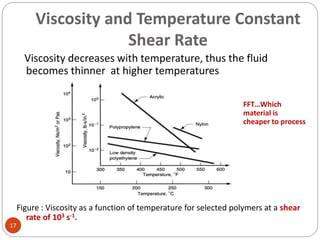
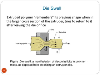
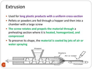
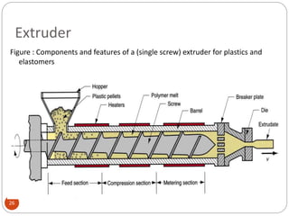
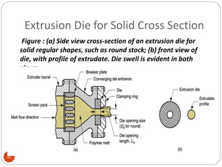
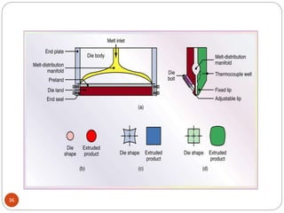
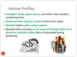
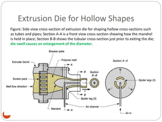
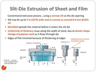
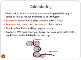
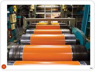
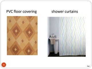
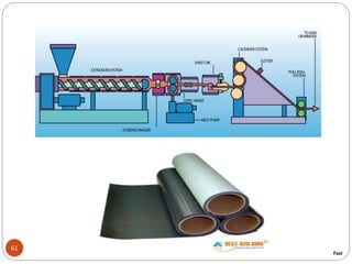
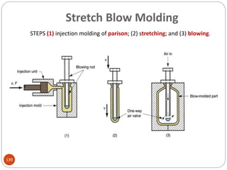
LECTURE # 05
HAFIZ ZAHID NABI
GHULAM MOEEN UDDIN
1
SHAPING PROCESSES FOR PLASTICS
2
Plastics & Polymers
3
 A term plastics has been derived from the Greek word
plastikos which means fit for moulding.defined as
organic,inorganic,natural or synthetic which can be
molded.
 Note that all plastics are polymers while all polymers are
not plastics.
 Polymer is derived from Greek word poly meaning many
and mer meaning part. Defined as a large molecule built
up by repetition of small, simple units held together by
covalent bond.
Plastics Vs Metals Selection Issues
4
 Complex geometries achievable by plastics
 Strength of material related selection issues
 Temeperature, pressure and humidity related
operating conditions of parts
 Part life
 Tolarencing and finishing
 Cost of material
 Cost of part processing i.e., less energy, less material
handling, net shaping processing of plastics i.e., single
step processing
Plastics
5
Advantages
• Light Weight
• High Strength-to-Weight Ratio
• Complex Parts - Net Shape
• Variety of Colors (or Clear)
• Corrosion Resistant
• Electrical Insulation
• Thermal Insulation
• High Damping Coefficient
• “Low” pressures and temp required
Disadvantages
• Creep
• Thermally Unstable-
Can’t withstand
Extreme Heat
• U-V Light Sensitive
• Relatively low stiffness
• Relatively low strength
• Difficult to
Repair/Rework
• Difficult to Sort/Recycle
Origins of Plastics - synthetic plastics.
6
 The main source of synthetic plastics is crude oil.
 Coal and natural gas are also used.
 Petrol, paraffin, lubricating oils and high petroleum gases are
bi-products, produced during the refining of crude oil.
 These gases are broken down into monomers. Monomers are
chemical substances consisting of a single molecule.
 A process called Polymerisation occurs when thousands of
monomers are linked together. The compounds formed as
called polymers.
 Combining the element carbon with one or more other
elements such as oxygen, hydrogen, chlorine, fluorine and
nitrogen makes most polymers.
Types of Polymers and Plastics
7
 There are three main different types of polymers:
thermoplastics, thermosets, and elastomers
 Thermosets once heated and formed permanent
chemical change occurs which cannot be retrived by
reheating.
 Thermoplastics can be reheated and reformed after
curing, i.e., after being heated and shaped earlier . It can
be cast, injected into a mold, or forced into or through
dies to produce a desired shape.
 Elastomers are sufficiently unique. When subjected to
heat & pressure behave first like thermoplastic &
subsequently highly elastic.
Thermoplastics
8
Long chain molecules
Thermosetting plastics
Cross-linked molecules
Plastic Products
9
 Plastics can be shaped into a wide variety of products:
 Molded parts
 Extruded sections
 Films
 Sheets
 Insulation coatings on electrical wires
 Fibers for textiles
 In addition, plastics are often the principal ingredient in other
materials, such as
 Paints and varnishes
 Adhesives
 Various polymer matrix composites
 Many plastic shaping processes can be adapted to produce
items made of rubbers and polymer matrix composites
Classification of Shaping Processes
10
 Extruded products with constant cross-section
 Continuous sheets and films
 Continuous filaments (fibers)
 Molded parts that are mostly solid
 Hollow molded parts with relatively thin walls
 Discrete parts made of formed sheets and films
 Castings
 Foamed products
History of Plastic Processing
11
 Plastic processing genesis was from rubber processing
industry
 Edwin Chaffee 1835 developed two roll steam heated
mixing mill for rubber
 1845 England ram driven rubber continuous coaters
for electric wires
 1879 England first patent for screw driven extruders
 1935 First extrusion machine for plastics
Polymer Melts
12
 To shape a thermoplastic polymer it must be heated
so that it softens to the consistency of a liquid
 In this form, it is called a polymer melt
 Important properties of polymer melts:
 Viscosity
 Viscoelasticity
Viscosity of Polymer Melts
13
Fluid property that relates shear stress to shear rate
during flow
 Due to its high molecular weight, a polymer melt is a
thick fluid with high viscosity
 Most polymer shaping processes involve flow through
small channels or die openings
 Flow rates are often large to increase the productivity,
leading to high shear rates and shear stresses, so
significant pressures are required to accomplish the
processes
Viscosity Relates SHEAR STRESS experienced
during fluid flow to RATE OF SHEAR
Viscosity
14
Section 3.4
Viscosity and Shear Rate Constant
Temp
15
Viscosity of a polymer melt decreases with shear rate, thus the
fluid becomes thinner at higher shear rates
Viscosity relationships for Newtonian fluid and typical polymer melt.
VISCOSITY DECRESES WITH SHEAR RATE AS FLUID BECOME THINNER AT HIGER
RATE OF SHEAR.THIS IS CALLED PSEUDOPLASTICITY.
16
The relationship between shear stress and shear rate:
.
  .


 
Shear stress Viscosity is the
constant of prop..
Shear rate
Newtonian Fluid
n
k )(
.
 
K=a constant corresponding to
the viscosity coefficient
n=flow behavior index
For polymer melts n<1
Pseudoplastic fluid
Viscosity and Shear Rate Const> Temp.
Viscosity and Temperature Constant
Shear Rate
17
Viscosity decreases with temperature, thus the fluid
becomes thinner at higher temperatures
Figure : Viscosity as a function of temperature for selected polymers at a shear
rate of 103 s-1.
FFT…Which
material is
cheaper to process
18
Viscosity
Viscosity of “polymer melt” is a function of temperature
Temperature increases  Viscosity decreases
Viscoelasticity
Polymer melts: an ability of recovering
Like many other liquid
Shear rate increases  Viscosity decreases
Combination of viscosity and elasticity
Possessed by both polymer solids and polymer melts
Example: die swell in extrusion, in which the hot plastic expands when exiting
the die opening
19
Viscoelasticity
Viscoelasticity
Polymer melts: an ability of recovering
Combination of viscosity and elasticity
Possessed by both polymer solids and polymer melts
Example: die swell in extrusion, in which the hot plastic expands when exiting
the die opening
Viscoelasticity is the property of a material that determines the strain it experiences
when subjected to combinations of stress and temperature over time.
Elastic behavior Viscoelastic behavior
20
Shaping Processes For Plastics
Die swell: due to the viscoelasticity
Extruded material “remembers” its former shape and
attempts to return to it after leaving die orifice
Compressive stresses do not relax immediately
when material exits orifice, and the unrelieved stress
causes cross-section to expand
THE AMOUNT OF DIE SWELL DEPENDS ON THE TIME OF THE
POLYMER MELT SPENDS IN DIE CHANNEL.INCRESING THE TIME IN
THE CHANNEL BY MEANS OF LONGER CHANNEL, REDUCES DIE
SWELL.
21
Extruded polymer "remembers" its previous shape when in
the larger cross section of the extruder, tries to return to it
after leaving the die orifice
Figure :Die swell, a manifestation of viscoelasticity in polymer
melts, as depicted here on exiting an extrusion die.
Die Swell
Fabrication of Plastics
23
 Fabrication Processes of Plastics
 Casting
 Blow Molding
 Compression Molding
 Transfer Molding
 Cold Molding
 Injection Molding
 Reaction Injection Molding
 Extrusion
 Thermoforming
 Rotational Molding
 Form Molding
 Other Plastic-Forming Processes
Extrusion … Metals, ceramics and Plastics
24
 Compression process in which material is forced to flow
through a die orifice to provide long continuous product
whose cross-sectional shape is determined by the shape
of the orifice
 Widely used for thermoplastics and elastomers to mass
produce items such as tubing, pipes, hose, structural
shapes, sheet and film, continuous filaments, and coated
electrical wire
 Carried out as a continuous process; extrudate is then cut
into desired lengths
Extrusion
25
 Used for long plastic products with a uniform cross-section
 Pellets or powders are fed through a hopper and then into a
chamber with a large screw
 The screw rotates and propels the material through a
preheating section where it is heated, homogenized, and
compressed
 To preserve its shape, the material is cooled by jets of air or
water spraying
Extruder
26
Figure : Components and features of a (single screw) extruder for plastics and
elastomers
Two Main Components of an Extruder
28
1. Barrel
2. Screw
 Die - not an extruder component. Special tool that must
be fabricated for particular profile to be produced.
Extruder Barrel:
 Internal diameter typically ranges from 25 to 150 mm (1.0 to
6.0 in.)
 L/D ratios usually between 10 and 30: higher ratios for
thermoplastics, lower ratios for elastomers
 Feedstock fed by gravity onto screw whose rotation moves
material through barrel
 Electric heaters melt feedstock; subsequent mixing and
mechanical working adds heat which maintains the melt
Extruder Screw
29
Divided into sections to serve several functions:
 Feed section - feedstock is moved from hopper and preheated
 Compression section - polymer is transformed into fluid, air
mixed with pellets is extracted from melt, and material is
compressed
 Metering section - melt is homogenized and sufficient pressure
developed to pump it through die opening
Wc=width of
channel
dc=diameter of
channel
Die End of Extruder
30
 Progress of polymer melt through barrel leads
ultimately to the die zone
 Before reaching die, the melt passes through a screen
pack - series of wire meshes supported by a stiff plate
containing small axial holes
 Functions of screen pack:
 Filter out contaminants and hard lumps (compact mass)
 Build pressure in metering section
 Straighten flow of polymer melt and remove its
"memory" of circular motion (inertia) from screw
Melt Flow in Extruder
31
 As screw rotates inside barrel, polymer melt is forced to
move forward toward die; as in an Archimedian screw
 Principal transport mechanism is drag flow, Qd, resulting
from friction between the viscous liquid and the rotating
screw
 Compressing the polymer melt through the die creates a
back pressure that reduces drag flow transport (called back
pressure flow, Qb )
 Resulting flow in extruder is Qx = Qd – Qb
Drag Flow Qd →
Back Pressure Flow Qb ←
Flight angle ‘A’? tan A = p / πD
32
The goal of the engineering analysis
Find the flow rate with respect to various parameters
in the system. These parameters include: parameters
of the screw, the clearance between the screw and
the inner surface of the barrel.
Die Configurations and Extruded Products
33
 The shape of the die orifice determines the cross-sectional
shape of the extrudate
 Common die profiles and corresponding extruded shapes:
 Solid profiles
 Hollow profiles, such as tubes
 Wire and cable coating
 Sheet and film
 Filaments
Extrusion of Solid Profiles
34
 Regular shapes such as
 Rounds
 Squares
 Irregular cross sections such as
 Structural shapes
 Door and window moldings
 Automobile trim
 House siding
Extrusion Die for Solid Cross Section
35
Figure : (a) Side view cross-section of an extrusion die for
solid regular shapes, such as round stock; (b) front view of
die, with profile of extrudate. Die swell is evident in both
views.
36
Hollow Profiles
37
 Examples: tubes, pipes, hoses, and other cross-sections
containing holes
 Hollow profiles require mandrel to form the shape
 Mandrel held in place using a spider
 Mandrel often includes an air channel through which air is
blown to maintain hollow form of extrudate during
hardening
Extrusion Die for Hollow Shapes
38
Figure: Side view cross-section of extrusion die for shaping hollow cross-sections such
as tubes and pipes; Section A-A is a front view cross-section showing how the mandrel
is held in place; Section B-B shows the tubular cross-section just prior to exiting the die;
die swell causes an enlargement of the diameter.
Wire and Cable Coating
39
 Polymer melt is applied to bare (not covered) wire as it is
pulled at high speed through a die
 A slight vacuum is drawn between wire and polymer to
promote adhesion of coating
 Wire provides rigidity during cooling - usually aided by
passing coated wire through a water trough
 Product is wound onto large spools at speeds up to 50 m/s
(10,000 ft/min)
Extrusion Die for Coating Wire
40
Figure :Side view cross-section of die for coating of electrical wire by extrusion.
Defects in Extrusion
41
 Melt fracture in which the stresses acting on the melt
before & during its flow through the die are so high as to
cause failure, manifested in the form of a highly irregular
surface on the extrudate.
Defects in Extrusion
42
Sharkskin in which the surface of the product becomes
roughened upon exiting die. As the melt flows through die
opening, friction at the interface results in a velocity profile
across the cross section.
Defects in Extrusion
43
If the velocity gradient become very high prominent marks
occur on the surface giving appearance like bamboo pole
hence name bambooing more severe effects
Do example 13.1 ,
Problems 13.1-13.4 at the end of book
Polymer Sheet and Film
44
 Film - thickness below 0.5 mm (0.020 in.)
 Packaging - product wrapping material, grocery bags, garbage bags
 Stock for photographic film
 Pool covers and liners for irrigation ditches
 Sheet - thickness from 0.5 mm (0.020 in.) to about 12.5 mm (0.5 in.)
 Flat window glazing
 Thermoforming stock
Materials
 All thermoplastic polymers
 Polyethylene, mostly low density PE
 Polypropylene
 Polyvinylchloride
 Cellophane (cellulose)
Sheet and Film Production Processes
45
 Sheet and Film Production Processes include:
 Slit Die Extrusion of Sheet and Film
 Blown Film Extrusion Process
 Calendaring
Slit-Die Extrusion of Sheet and Film
46
Conventional extrusion process , using a narrow slit as the die opening
 Slit may be up to 3 m (10 ft) wide and as narrow as around 0.4 mm (0.015
in)
 Manifold spreads the material before it enters the slit die
 Uniformity of thickness issue along the width of stock, due to drastic shape
change of polymer melt as it flows through die
 Edges of film trimmed because of thickening at edges Manifold Presses the fluid
by diameter change
47
 For high production rates (5 m/s) and address die swell,
an efficient method of cooling and collecting the film.
 This is done by directing extrude in quenching bath of
water or chilled rolls is called chill roll extrusion.
Water quenched Chill Roll Quenching
Blown-Film Extrusion Process
49
Extrusion + Blowing to produce a tube of thin film
 Process sequence:
 Extrusion of tube
 Cooling
 Air is blown into tube to maintain uniform film thickness
 Features
 Less production rate than the slit die method
 Stronger and thinner film
 Can be made into bags
Fast
50
SlSoldification will start
above frost line
Figure : Blown film
process for high
production of thin
tubular film. Pinch rolls
Frost Line
(cooling starts)
Constant air pressure
51
Fast
52
Fast
Calendaring
54
Feedstock (rubbers or rubbery pastes PVC) passed through a
series of rolls to reduce thickness to desired gage
 Expensive equipment, high production rates 2.5 m/s
 Temperature, speed and pressure of rollers, critical
 Good surface finish and high gage accuracy
 Products: PVC floor covering, shower curtains, vinyl table cloths,
pool liners, and inflatable boats and toys
55
Fast
56
PVC floor covering shower curtains
Fast
57
vinyl table cloths pool liners
Fast
58
Fast
59
INFLATABLE BOATS
Fast
60
Inflatable
Toys
Fast
61
Fast
Fiber and Filament Products
62
 Definitions:
 Fiber - a long, thin strand whose length is at least 100 times its
cross-section
 Filament - a fiber of continuous length
 Applications:
 Fibers and filaments for textiles
 Most important application
 Reinforcing materials in polymer composites
 Growing application, but still small compared to textiles
Materials for Fibers and Filaments
63
Fibers can be natural or synthetic
 Natural fibers constitute ~ 25% of total market
 Cotton is by far the most important staple
 Wool production is significantly less than cotton
 Synthetic fibers constitute ~ 75% of total fiber market
 Polyester is the most important
 Others: nylon, acrylics, and rayon
64
Yarn is a long continuous length of interlocked fibers,
suitable for use in the production of textiles,
sewing, knitting, weaving, embroidery and rope
making.
Fast
Fiber and Filament Production - Spinning
65
For synthetic fibers, spinning = extrusion of polymer melt
or solution through a spinneret (a die with multiple small
holes), then drawing and winding onto a bobbin (reel or
cone)
 The term is a holdover from methods used to draw and
twist natural fibers into yarn or thread
 Three variations, depending on polymer :
1. Melt spinning
2. Dry spinning
3. Wet spinning
Melt Spinning
66
Starting polymer is heated to molten state and pumped
through spinneret
 Typical spinneret is 6 mm (0.25 in) thick and contains
approximately 50 holes of diameter 0.25 mm (0.010 in)
 Holes are counter sunk (L/D 5:1)
 Filaments are drawn and air cooled before being
spooled onto bobbin. Air cooling so that fiber can be
extended
 Significant extension and thinning of filaments occur
while polymer is still molten, so final diameter wound
onto bobbin may be only 1/10 of extruded size
 Used for polyester and nylon filaments
Melt Spinning
67
Dry Spinning
69
Starting polymer is in solution and solvent can be
separated by evaporation. So no melting
 First step is extrusion through spinneret
 Extrudate is pulled through a heated chamber which
removes the solvent, leaving the polymer
 Used for filaments of cellulose acetate and acrylics
Wet Spinning
70
Polymer is again in solution form , but the solvent is non-volatile
To separate polymer, extrudate is passed through a liquid
chemical that coagulates or precipitates the polymer into
coherent strands which are then collected onto bobbins
Used to produce filaments of rayon (regenerated cellulose)
Post Processing of Filaments
71
 Filaments produced by any of the three processes are
usually subjected to further cold drawing to align crystal
structure along direction of filament axis
 Extensions has effect is to significantly increase tensile
strength
 Drawing is done by pulling filament between two spools,
where winding spool is driven at a faster speed than
unwinding spool
COATING PROCESS
72
 Plastic coating involves application of a layer of given polymer
on to substrate material (on which something is deposited).
Three categories are distinguished
1. Wire & cable coating:
It is basically done by extrusion process
2. Planer coating:
It is used to coat fabrics,paper,cardboard and metal foil.
 Roll Method: the polymer coating material is squeezed
against the material by means of opposing rolls. Fast settling
materials
 Doctor blade method: a knife edge controls the amount of
polymer melt that is coated on to the material.
73
 COUNTOUR COATING: it is done for three dimensional
objects accomplished by dipping or spraying.
 DIPPING: it involves submersion of the object into a
suitable bath of polymer melt or solution.
 SPRYING: such as spray painting is an alternative method
for applying a polymer coating to a solid object.
COATING PROCESS
Injection Molding
74
Polymer is heated to a highly plastic state and forced to
flow under high pressure into a mold cavity where it
solidifies and the part (molding) is then removed from
cavity
 Discrete components almost always to net shape
 Typical cycle time 10 to 30 sec, but cycles of one
minute or more are not uncommon
 Mold may contain multiple cavities, so multiple
moldings are produced each cycle
 This process is used to form complex plastic parts.
Typical injection molded parts are fittings, containers,
bottle tops, housings, and much more.
Injection Molded Parts
75
 Shape limitations:
 Capability to fabricate a mold whose cavity is the same
geometry as part
 Shape must allow for part removal from mold
 Part size from  50 g (2 oz) up to  25 kg (more than 50
lb), e.g., automobile bumpers
 Injection molding is economical only for large production
quantities due to high cost of molds and machine
operation and maintenance costs
Materials for Injection Molding
76
 Injection molding is the most widely used molding
process for thermoplastics
 Some thermosets and elastomers are injection molded
 Modifications in equipment and operating parameters
must be made to avoid premature cross linking of these
materials before injection
77
Two principal components:
1. Injection unit (melts and homogenize the polymer melt)
Melts and delivers polymer melt
Operates much like an extruder
2. Clamping unit
Opens and closes mold each injection cycle
Reciprocating screw type
more commonly used
Operates in cycles
Injection Unit of Molding Machine
79
Consists of barrel fed from one end by a hopper
containing supply of plastic pellets
 Inside the barrel is a screw which:
1. Rotates for mixing and heating polymer
2. Acts as a ram (i.e., plunger) to inject molten plastic into
mold
 Non return valve near tip of screw prevents melt
flowing backward along screw threads
 Later in molding cycle ram retracts(back in) to its
former position
Clamping Unit of Molding Machine
80
 Functions:
1. Holds two halves of mold in proper alignment with each other
2. Keeps mold closed during injection by applying a clamping
force sufficient to resist injection force
3. Opens and closes mold at the appropriate times in molding
cycle
4. Fixed and movable platens
81
(1) Mold is closed and clamped and sealed
Injection Molding Cycle
82
(2) melt is injected into cavity.
Starts to cool with the cold surface of the cavity
Ram pressure maintained to keep the cavity filled after cooling
contraction
Injection Molding Cycle
83
(3) screw is retracted.
Allows for refilling of the die end of the barrel
Injection Molding Cycle
Cooling lines
84
(4) mold opens and part is ejected.
Injection Molding Cycle
The Mold
89
 The special tool in injection molding
 Custom designed and fabricated for the part to be
produced
 When production run is finished, the mold is replaced
with a new mold for the next part
 Various types of mold for injection molding:
 Two-plate mold
 Three-plate mold
 Hot-runner mold
Two Plate Mold Features
90
 Cavity – geometry of part but slightly oversized to allow for
shrinkage
 Created by machining of mating surfaces of two mold halves
 Could be single or multiple cavities
 Distribution channel through which polymer melt flows
from nozzle into mold cavity
 Sprue – extra space, leads from nozzle into mold
 Runners – channel that lead from sprue to cavity (or cavities)
 Gates - constrict flow of plastic into cavity
91
Figure: Details of a two plate mold for thermoplastic injection molding: (a)
closed. Mold has two cavities to produce two cup shaped parts with
each injection shot.
Two-Plate Mold for Producing Two Cups
92
(b) open
Two-Plate Mold
93
More Two Plate Mold Features
95
 Ejection system – to eject molded part from cavity at
end of molding cycle
 Ejector pins built into moving half of mold usually
accomplish this function
 Cooling system - consists of external pump connected
to passageways in mold, through which water is
circulated to remove heat from the hot plastic
 Air vents – to permit evacuation of air from cavity as
polymer melt rushes in
Three Plate Mold
96
Separate parts from sprue and runner when mold opens
 Advantages over two-plate mold:
 As mold opens, runner and parts disconnect and drop into two
containers under mold
 Allows automatic operation of molding machine
 Seam at the bottom of the part
Hot Runner Mold
98
 Eliminates solidification of sprue and runner by locating
heaters around the corresponding runner channels
 While plastic in mold cavity solidifies, material in sprue
and runner channels remains molten, ready to be injected
into cavity in next cycle
 Advantage:
 Saves material that otherwise would be scrap in the unit
operation
Injection Molding Machines Types
99
 Injection molding machines differ in both injection unit
and clamping unit
 Name of injection molding machine is based on the type
of injection unit used
 Reciprocating-screw injection molding machine
 Plunger-type injection molding machine
 Several clamping designs
 Mechanical (toggle)
 Hydraulic
Plunger Type Injection Molding Press
100
Material is stored (in pellet form) in the hopper
Band heaters heat material through shooting pot
Stroke of the plunger meters the shot size
Screw Plasticizers (Two stage machines)
102
Virtually ALL industrial presses are screw type presses
Added benefits of screw
1) Larger throughput
2) Obtain a more homogeneous melt (better mix)
3) More consistent from shot to shot
4) Added heat to melt- from action of screw
Press Parameters
104
3 parameters commonly used to describe press capacity
1) Clamping force- Force available to hold platens together (tons)
Can be from “In-line” Hydraulic/Pneumatic Cylinder
Mechanical Toggle Clamp
Hydro mechanical- “In-line” cylinder & toggle
2) Shot size- Amount of material that can be transferred to mold in a shot
3) Injection Pressure- Maximum pressure that can be developed at the sprue
to force the plastic into the mold cavity
Clamping Mechanisms
106
“In line” hydraulic cylinder
Good Force control,
but requires large hydraulics, slow
Toggle Clamp
High Productivity,
Poor Force Control
Hydromechancial Clamp
Uses toggle mechanism for most of travel, but
Locking force is provided by an in line cylinder
Shrinkage
Reduction in size during cooling from molding to room
temperature
 Polymers have high thermal expansion coefficients, so
significant shrinkage occurs during solidification and cooling
in mold
 Typical shrinkage values:
107
108
 Dimensions of mold cavity must be larger than specified part
dimensions: Dc = Dp + DpS + DpS2
where Dc = dimension of cavity; Dp = molded part dimension,
and S = shrinkage value and the third term on right hand side corrects
for shrinkage in the shrinkage.
Shrinkage Factors
 Injection pressure – higher pressures force more material into
mold cavity to reduce shrinkage
 Compaction time - similar effect – longer time forces more
material into cavity to reduce shrinkage
 Molding temperature - higher temperatures lower polymer melt
viscosity, allowing more material to be packed into mold to reduce
shrinkage
 Part thickness– thicker parts show more shrinkage
Injection Molding Defects
• Short Shot
• Flashing
• Weld Lines
• Ejector Pin Marks
• Sink Marks
109
Short Shot
• Insufficient material to fill the mold cavity
• Material solidifies too soon.
• Insufficient injection pressure
• Insufficient time allowed during the injection process.
110
Flashing
Part w/ Moderate-Heavy Flash
Flash
• Basically, the material overflows the cavity.
• Too much injection pressure
• Too much injection time
• Insufficient clamping force.
• Poorly designed or machined die that does not
properly seal off the cavity.
111
Sink Marks and Voids
• Sink marks occur at excessively thick wall sections, or where there
are abrupt changes in thickness-
• The surface solidifies too fast but the late contraction of the inner
material forms depressions in the surface
Issue can be addresses by:
Increasing packing pressure
Carefully designing the parts and avoiding thick cross sections
112
Weld Lines
• Weld lines are created when two flow fronts come together in
the mold around a core or convex cavities in the mold
• Weld lines decrease the strength of the part
• Weld lines are more pronounced if melt is cooler when fronts
meet. Also if flow fronts are moving into one another.
113
Thermoplastic Foam Injection Molding
Molding of thermoplastic parts that possess dense outer skin
surrounding lightweight foam center
 Part has high stiffness- to- weight ratio suited to structural
applications
 Produced either by introducing a gas into molten plastic in
injection unit or by mixing a gas producing ingredient with
starting pellets
 A small amount of melt is injected into mold cavity, where it
expands to fill cavity
 Foam in contact with cold mold surface collapses to form dense
skin, while core retains cellular structure
114
Injection Molding of Thermosets
 Equipment and operating procedure must be modified to
avoid premature cross linking of TS polymer
 Reciprocating screw injection unit with shorter barrel length
 Temperatures in barrel are relatively low
 Melt is injected into a heated mold (150_ 230 ◦C), where
cross linking occurs to cure the plastic
 Curing in the mold is the most time-consuming step in the
cycle
 Mold is then opened and part is removed
115
Reaction Injection Molding
Two highly reactive liquid ingredients are mixed and
immediately injected into a mold cavity where chemical
reactions leading to solidification occur
 RIM was developed with polyurethane to produce large
automotive parts such as bumpers and fenders
 RIM polyurethane parts possess a foam internal structure
surrounded by a dense outer skin
 Other materials used in RIM: epoxies, and urea
formaldehyde
116
117
 Two or more liquid reactants are mixed under pressure
 The mixture then flows through a pressure-reducing
chamber and into a mold
 Exothermic reaction causes the thermosets to polymerize
 Curing times are typically less than a minute
 Low processing temperatures and low injection pressures
 Typical for casting large parts
Show Injection Molding Video # 1
120
Compression Molding (Thermosets)
 A widely used molding process for thermosetting
plastics
 Common examples rubber tires and polymer matrix
composite parts
 Molding compound available in several forms:
powders or pellets, liquid, or perform
 Amount of charge must be precisely controlled to
obtain repeatable consistency in the molded product
 Charges can be solid, liquid or preforms
121
Compression Molding Steps
Figure :Compression molding for thermosetting plastics: (1) charge is
loaded, (2) and (3) mold closed charge is compressed and cured, and (4)
part is ejected and removed.
122
Typical for Thermosets`
Molds for Compression Molding
 Simpler than injection molds
 No sprue and runner system in a compression mold
 Process itself generally limited to simpler part geometries due
to lower flow capabilities of TS materials
 Mold must be heated, usually by electric resistance, steam, or
hot oil circulation
 Typical molding materials: phenolics, melamine, epoxies,
urethanes, and elastomers
 Typical compression-molded products:
 Electric plugs, sockets, and housings; pot handles, and
dinnerware plates
124
125
Transfer Molding (Thermosets)
TS charge is loaded into a chamber immediately ahead of
mold cavity, where it is heated;
Pressure is then applied to force soft polymer to flow into
heated mold where it cures
 Two variants:
 Pot transfer molding - charge is injected from a "pot" through
a vertical sprue channel into cavity
 Plunger transfer molding – plunger injects charge from a
heated well through channels into cavity
126
(1) charge is loaded into pot, (2) softened polymer is pressed into mold
cavity and cured, and (3) part is ejected.
Controlled Heating In the Transfer Pot and the Mold for CURING
Pot Transfer Molding
127
wastage
Plunger transfer molding: (1) charge is loaded into heated pot, (2)
softened polymer is pressed into mold cavity and cured, and (3) part is
ejected.
Plunger Transfer Molding
128
Multiple Parts Easier to make, generally lesser scarp
Compression vs. Transfer Molding
 In both TM processes, scrap is produced each cycle as
leftover material, called the cull
 The TS scrap cannot be recovered
 Transfer molding is capable of molding more intricate part
shapes than compression molding but not as intricate as
injection molding
 Transfer molding lends itself to molding with inserts, in
which a metal or ceramic insert is placed into cavity prior
to injection, and the plastic bonds to insert during molding
130
Blow Molding
Molding process in which air pressure is used to inflate(expand
by filling with air or gas) soft plastic into a mold cavity
 Important for making seam less one-piece hollow plastic parts
with thin walls, such as bottles
 High production quantities, large sizes (5ml to 10000 gallons)
 Accomplished in two steps:
1.Fabrication of a starting tube, called a parison
2.Inflation of the tube to desired final shape
 Forming the parison is accomplished by either
 Extrusion or
 Injection molding
132
Blow Molding Types
Based on the formation of PARISON
 Extrusion Blow Molding
 Injection Blow Molding
 Stretch Blow Molding
 Blow Molding Limited to TPs
 Thermoplastics
 HDPE and HMWPE
133
STEPS: (1) extrusion of parison; (2) parison is pinched at the top and sealed
at the bottom around a metal blow pin as the two halves of the mold come
together; (3) the tube is inflated so that it takes the shape of the mold cavity;
and (4) mold is opened to remove the solidified part.
Extrusion Blow Molding
134
135
STEPS (1) parison is injected around a blowing rod; (2) injection mold is
opened and parison is transferred to a blow mold; (3) soft polymer is
inflated to conform to the blow mold; and (4) blow mold is opened and
blown product is removed.
Injection Blow Molding
136
Stretch Blow Molding
Variation of injection blow molding in which blowing rod
stretches the soft parison for a more favorable stressing of
polymer than conventional blow molding
 Resulting structure is more rigid, more transparent, and
more impact resistant
 Most widely used material is polyethylene terephthalate
(PET) which has very low permeability and is strengthened
by stretch blow molding
 Combination of properties makes it ideal as container for
carbonated beverages
138
STEPS (1) injection molding of parison; (2) stretching; and (3) blowing.
Stretch Blow Molding
139
Materials and Products in Blow Molding
 Blow molding is limited to thermoplastics
 Materials: high density polyethylene, polypropylene (PP),
polyvinylchloride (PVC), and polyethylene terephthalate
(PET)
 Products: disposable containers for beverages and other
liquid consumer goods, large shipping drums (55 gallon)
for liquids and powders, large storage tanks (2000 gallon),
gasoline tanks, toys, and hulls for sail boards and small
boats
140
Rotational Molding or Rotomolding
 Typically for complex outer geometries
 Typical products are tanks, bins, refuse containers, doll parts,
footballs, helmets, and boat hulls
 A mold or cavity is filled with a specific amount of
thermoplastic powder or liquid
 The molds are then placed in an oven and rotated
simultaneously about two perpendicular axes
 The resin is evenly distributed across the mold walls
 All of starting material is used in the product, no scrap is
generated.
141
Rotational Molding
142
 Rotational molding is used for large plastic parts.
 The thin-walled metal mold is a split mode made of two pieces
and is designed to be rotated about two perpendicular axes.
 A premeasured quantity of finely ground plastic material is
placed inside a warm mold.
 The mold is then heated, usually in a large oven, while it is
rotated about the two axes.
 The action tumbles(falls suddenly) the powder against the mold
where heating fuses the powder without melting it.
 In some cases, a cross linking agent is added to the powder, and
cross linking occurs after the part is formed in the mold by
continued heating.
 Typical parts are tanks, trash cans, boat hulls, buckets, housings,
toys, carrying cases, and footballs..
143
146
Show Blow Molding Video
Thermoforming
 Flat thermoplastic sheet or film is heated and
deformed into desired shape using a mold
 Thermoplastic sheet material is heated and then
placed over a mold
 A vacuum, pressure, or mechanical tool is applied to
draw the material into the mold
 Heating by radiant electric heaters located on one or
both sides (5 inches) of starting plastic sheet or film
 Widely used in packaging of products and to fabricate
large items such as bathtubs, contoured skylights, and
internal door liners for refrigerators
147
Steps (1) a flat plastic sheet is softened by heating (2) the softened sheet is placed
over a concave mold cavity, (3) a vacuum draws the sheet into the cavity (4)
plastic hardens on contact with the cold mold surface, and the part is removed
and subsequently trimmed from the web
Vacuum Thermoforming with – ve Mold
148
Concave Molds, Negative Vacuum, vacuum holes are very small 0.8mm so the
geometric effect is negligible, limited to 1 atm pressure range
Convex Molds, Negative Vacuum
Vacuum Thermoforming with + ve Mold
149
Pressure Thermoforming
150
 Positive pressure to force the heated plastic into mold
cavity. This is called pressure thermoforming or blow
forming.
 Higher pressure can be developed 3 to 4 atm. The sheet is
pressurized from above into mold cavity.
151
 Preheat and stretch the sheet before draping it over the
convex mold.
Can be utilized alone as a method to produce globe-shaped parts such as skylight
windows and transparent domes.
Improving Unifom Thinning
Mechanical Thermoforming
152
 In the pure mechanical forming method.
 Matching positive and negative molds that are brought
together against the heated plastic sheet, forcing it to
assume their shape
Its advantages are better dimensional control and the opportunity for surface
detailing on both sides of the part. The disadvantage is that two mold halves
are required; the molds for the other two methods are therefore less costly.
Materials for Thermoforming
 Only thermoplastics can be thermoformed,
 Extruded sheets of thermosetting or elastomeric polymers
have already been cross linked and cannot be softened by
reheating
 Common TP polymers: polystyrene, cellulose acetate,
cellulose acetate butyrate, ABS, PVC, acrylic,
polyethylene, and polypropylene
153
Applications of Thermoforming
 Thin films: blister packs and skin packs for packaging
commodity products such as cosmetics, toiletries, small
tools, and fasteners (nails, screws, etc.)
 Thicker sheet stock: boat hulls, shower stalls, advertising
displays and signs, bathtubs, certain toys, contoured
skylights, internal door liners for refrigerators
154
Casting
Pouring liquid resin into a mold, using gravity to fill cavity,
where polymer hardens
 Both thermoplastics and thermosets are cast
 Thermoplastics: acrylics, polystyrene, polyamides (nylons)
and PVC
 Thermosetting polymers: polyurethane, unsaturated
polyesters, phenolics, and epoxies
 Simpler mold
 Suited to low quantities
 Cast item is free from residual stresses
 High degree of flat surface & optical properties
158
Steps in casting
159
1. Heating the thermoplastic to highly fluid state so it can
be poured & filled mould cavity and then permitting it
too cool & solidify.
2. Using a low molecular weight monomer and
polymerizing it in the mold to form a high molecular
weight thermoplastics.
Processes for Plastics and Electrical
Assemblies
Figure : Schematic illustration of (a) casting, (b) potting, and (c) encapsulation processes
for plastics and electrical assemblies, where the surrounding plastic serves as a dielectric.
160
Polymer Foam
A polymer and gas mixture that gives the material a
porous or cellular structure
 Most common polymer foams: polystyrene (Styrofoam, a
trademark), polyurethane
 Other polymers: natural rubber ("foamed rubber") and
polyvinylchloride (PVC)
161
Applications of Polymer Foams
 Characteristic properties of polymer foams, and the ability to control elastic
behavior by selection of base polymer, make these materials suitable for
certain applications
 Applications: hot beverage cups, heat insulating structural materials, cores
for structural panels, packaging materials, cushion materials for furniture and
bedding, padding for automobile dashboards, and products requiring
buoyancy
Figure :Two polymer foam structures: (a) closed cell and (b) open cell.163
Foaming Processes
164
 Common gases in foams are air, nitrogen and Co2 are
introduced. The gases are introduced by several methods,
called foaming processes. it includes
1. Mixing of liquid resins with air by mechanical agitation
then heat or chemical reactions harden it.
2. Mixing a physical blowing agent with polymer
3. Mixing polymer with chemical compounds, called
chemical blowing agent.
The way gas is introduced in polymer matrix
distinguished two basic foam structures. Open & closed
structures.
165
 Closed cell: where gas pores are roughly spherical and
completely separated from each other by polymer
matrix.
 Open Cell: in which pores are interconnected to some
extent, allowing passage of a liquid through foam.
Two polymer foam structures: (a) closed cell
and (b) open cell.
 Polystyrene (PS) is a thermoplastic polymer
 A physical or chemical blowing agent is fed into polymer melt near
die end of extruder barrel; thus, extrudate consists of expanded
polymer
 Products: large sheets and boards that are subsequently cut to size
for heat insulation panels and sections
 Expandable foam molding
 Molding material consists of prefoamed polystyrene beads
 Beads are fed into mold cavity where they are further expanded
and fused together to form the molded product
 Products: hot beverage cups,
Extrusion of Polystyrene Foams
166
Shaping of Polyurethane Foams
 Polyurethane can be thermosetting, elastomer or
thermoplastic (less common)
 Polyurethane foam products are made in a one-step process
in which the two liquid ingredients are mixed and
immediately fed into a mold or other form
 Polymer is synthesized and part geometry is created at the
same time
 Shaping processes for polyurethane foam:
 Spraying
 Pouring
 Cutting
168
Product Design Guidelines
 Strength and stiffness
 Plastics are not as strong or stiff as metals
 Avoid applications where high stresses will be encountered
 Creep resistance is also a limitation
 Strength to weight ratios for some plastics are competitive with
metals in certain applications
 Impact Resistance
 Capacity of plastics to absorb impact is generally good; plastics
compare favorably with most metals
 Service temperatures
 Limited relative to metals and ceramics
 Thermal expansion
 Dimensional changes due to temperature changes much more
significant than for metals
169
170
 Many plastics are subject to degradation from sunlight
and other forms of radiation
 Some plastics degrade in oxygen and ozone
atmospheres
 Plastics are soluble in many common solvents
 Plastics are resistant to conventional corrosion
mechanisms that afflict(pain or suffering) many metals
Wall thickness
 Uniform wall thickness is desirable in an extruded
cross section
 Variations in wall thickness result in non-uniform
plastic flow and uneven cooling which tend to warp
extrudate
171
 Hollow sections
 Hollow sections complicate die design and plastic
flow
 Desirable to use extruded cross-sections that are
not hollow yet satisfy functional requirements
 Corners
 Sharp corners, inside and outside, should be
avoided in extruded cross sections
 They result in uneven flow during processing and
stress concentrations in the final product
Product Design Guidelines: Moldings
 Economic production quantities
 Each part requires a unique mold, and the mold for any
molding process can be costly, particularly for injection
molding
 Minimum production quantities for injection molding are
usually around 10,000 pieces
 For compression molding, minimum quantities are 1000
parts, due to simpler mold designs
 Transfer molding lies between injection molding and
compression molding
172
Product Design Guidelines: Moldings
 Part complexity
 An advantage of plastic molding is that it allows multiple functional
features to be combined into one part
 Although more complex part geometries mean more costly molds, it
may nevertheless be economical to design a complex molding if the
alternative involves many individual components that must be
assembled.
 Wall thickness
 Thick cross sections are wasteful of material, more likely to cause
warping due to shrinkage, and take longer to harden
 Reinforcing ribs
 Achieves increased stiffness without excessive wall thickness
 Ribs should be made thinner than the walls they reinforce to minimize
sink marks on outside wall
173
174
 Corner radii and fillets
 Sharp corners, both external and internal, are undesirable in
molded parts
 They interrupt smooth flow of the melt, tend to create
surface defects, and cause stress concentrations in the part
 Holes
 Holes are quite feasible in plastic moldings, but they
complicate mold design and part removal
 Draft
 A molded part should be designed with a draft on its sides
to facilitate removal from mold
 Especially important on inside wall of a cup shaped part
because plastic contracts against positive mold shape
 Recommended draft:
 For thermosets, ~ 1/2 to 1
 For thermoplastics, ~ 1/8 to 1/2
Product Design Guidelines: Moldings
 Tolerances
 Although shrinkage is predictable under closely controlled
conditions, generous tolerances are desirable for injection
moldings because of
 Variations in process parameters that affect shrinkage
 Diversity of part geometries encountered
175

Shaping processes for plastics

  • 1.
    LECTURE # 05 HAFIZZAHID NABI GHULAM MOEEN UDDIN 1 SHAPING PROCESSES FOR PLASTICS
  • 2.
  • 3.
    Plastics & Polymers 3 A term plastics has been derived from the Greek word plastikos which means fit for moulding.defined as organic,inorganic,natural or synthetic which can be molded.  Note that all plastics are polymers while all polymers are not plastics.  Polymer is derived from Greek word poly meaning many and mer meaning part. Defined as a large molecule built up by repetition of small, simple units held together by covalent bond.
  • 4.
    Plastics Vs MetalsSelection Issues 4  Complex geometries achievable by plastics  Strength of material related selection issues  Temeperature, pressure and humidity related operating conditions of parts  Part life  Tolarencing and finishing  Cost of material  Cost of part processing i.e., less energy, less material handling, net shaping processing of plastics i.e., single step processing
  • 5.
    Plastics 5 Advantages • Light Weight •High Strength-to-Weight Ratio • Complex Parts - Net Shape • Variety of Colors (or Clear) • Corrosion Resistant • Electrical Insulation • Thermal Insulation • High Damping Coefficient • “Low” pressures and temp required Disadvantages • Creep • Thermally Unstable- Can’t withstand Extreme Heat • U-V Light Sensitive • Relatively low stiffness • Relatively low strength • Difficult to Repair/Rework • Difficult to Sort/Recycle
  • 6.
    Origins of Plastics- synthetic plastics. 6  The main source of synthetic plastics is crude oil.  Coal and natural gas are also used.  Petrol, paraffin, lubricating oils and high petroleum gases are bi-products, produced during the refining of crude oil.  These gases are broken down into monomers. Monomers are chemical substances consisting of a single molecule.  A process called Polymerisation occurs when thousands of monomers are linked together. The compounds formed as called polymers.  Combining the element carbon with one or more other elements such as oxygen, hydrogen, chlorine, fluorine and nitrogen makes most polymers.
  • 7.
    Types of Polymersand Plastics 7  There are three main different types of polymers: thermoplastics, thermosets, and elastomers  Thermosets once heated and formed permanent chemical change occurs which cannot be retrived by reheating.  Thermoplastics can be reheated and reformed after curing, i.e., after being heated and shaped earlier . It can be cast, injected into a mold, or forced into or through dies to produce a desired shape.  Elastomers are sufficiently unique. When subjected to heat & pressure behave first like thermoplastic & subsequently highly elastic.
  • 8.
  • 9.
    Plastic Products 9  Plasticscan be shaped into a wide variety of products:  Molded parts  Extruded sections  Films  Sheets  Insulation coatings on electrical wires  Fibers for textiles  In addition, plastics are often the principal ingredient in other materials, such as  Paints and varnishes  Adhesives  Various polymer matrix composites  Many plastic shaping processes can be adapted to produce items made of rubbers and polymer matrix composites
  • 10.
    Classification of ShapingProcesses 10  Extruded products with constant cross-section  Continuous sheets and films  Continuous filaments (fibers)  Molded parts that are mostly solid  Hollow molded parts with relatively thin walls  Discrete parts made of formed sheets and films  Castings  Foamed products
  • 11.
    History of PlasticProcessing 11  Plastic processing genesis was from rubber processing industry  Edwin Chaffee 1835 developed two roll steam heated mixing mill for rubber  1845 England ram driven rubber continuous coaters for electric wires  1879 England first patent for screw driven extruders  1935 First extrusion machine for plastics
  • 12.
    Polymer Melts 12  Toshape a thermoplastic polymer it must be heated so that it softens to the consistency of a liquid  In this form, it is called a polymer melt  Important properties of polymer melts:  Viscosity  Viscoelasticity
  • 13.
    Viscosity of PolymerMelts 13 Fluid property that relates shear stress to shear rate during flow  Due to its high molecular weight, a polymer melt is a thick fluid with high viscosity  Most polymer shaping processes involve flow through small channels or die openings  Flow rates are often large to increase the productivity, leading to high shear rates and shear stresses, so significant pressures are required to accomplish the processes Viscosity Relates SHEAR STRESS experienced during fluid flow to RATE OF SHEAR
  • 14.
  • 15.
    Viscosity and ShearRate Constant Temp 15 Viscosity of a polymer melt decreases with shear rate, thus the fluid becomes thinner at higher shear rates Viscosity relationships for Newtonian fluid and typical polymer melt. VISCOSITY DECRESES WITH SHEAR RATE AS FLUID BECOME THINNER AT HIGER RATE OF SHEAR.THIS IS CALLED PSEUDOPLASTICITY.
  • 16.
    16 The relationship betweenshear stress and shear rate: .   .     Shear stress Viscosity is the constant of prop.. Shear rate Newtonian Fluid n k )( .   K=a constant corresponding to the viscosity coefficient n=flow behavior index For polymer melts n<1 Pseudoplastic fluid Viscosity and Shear Rate Const> Temp.
  • 17.
    Viscosity and TemperatureConstant Shear Rate 17 Viscosity decreases with temperature, thus the fluid becomes thinner at higher temperatures Figure : Viscosity as a function of temperature for selected polymers at a shear rate of 103 s-1. FFT…Which material is cheaper to process
  • 18.
    18 Viscosity Viscosity of “polymermelt” is a function of temperature Temperature increases  Viscosity decreases Viscoelasticity Polymer melts: an ability of recovering Like many other liquid Shear rate increases  Viscosity decreases Combination of viscosity and elasticity Possessed by both polymer solids and polymer melts Example: die swell in extrusion, in which the hot plastic expands when exiting the die opening
  • 19.
    19 Viscoelasticity Viscoelasticity Polymer melts: anability of recovering Combination of viscosity and elasticity Possessed by both polymer solids and polymer melts Example: die swell in extrusion, in which the hot plastic expands when exiting the die opening Viscoelasticity is the property of a material that determines the strain it experiences when subjected to combinations of stress and temperature over time. Elastic behavior Viscoelastic behavior
  • 20.
    20 Shaping Processes ForPlastics Die swell: due to the viscoelasticity Extruded material “remembers” its former shape and attempts to return to it after leaving die orifice Compressive stresses do not relax immediately when material exits orifice, and the unrelieved stress causes cross-section to expand THE AMOUNT OF DIE SWELL DEPENDS ON THE TIME OF THE POLYMER MELT SPENDS IN DIE CHANNEL.INCRESING THE TIME IN THE CHANNEL BY MEANS OF LONGER CHANNEL, REDUCES DIE SWELL.
  • 21.
    21 Extruded polymer "remembers"its previous shape when in the larger cross section of the extruder, tries to return to it after leaving the die orifice Figure :Die swell, a manifestation of viscoelasticity in polymer melts, as depicted here on exiting an extrusion die. Die Swell
  • 22.
    Fabrication of Plastics 23 Fabrication Processes of Plastics  Casting  Blow Molding  Compression Molding  Transfer Molding  Cold Molding  Injection Molding  Reaction Injection Molding  Extrusion  Thermoforming  Rotational Molding  Form Molding  Other Plastic-Forming Processes
  • 23.
    Extrusion … Metals,ceramics and Plastics 24  Compression process in which material is forced to flow through a die orifice to provide long continuous product whose cross-sectional shape is determined by the shape of the orifice  Widely used for thermoplastics and elastomers to mass produce items such as tubing, pipes, hose, structural shapes, sheet and film, continuous filaments, and coated electrical wire  Carried out as a continuous process; extrudate is then cut into desired lengths
  • 24.
    Extrusion 25  Used forlong plastic products with a uniform cross-section  Pellets or powders are fed through a hopper and then into a chamber with a large screw  The screw rotates and propels the material through a preheating section where it is heated, homogenized, and compressed  To preserve its shape, the material is cooled by jets of air or water spraying
  • 25.
    Extruder 26 Figure : Componentsand features of a (single screw) extruder for plastics and elastomers
  • 26.
    Two Main Componentsof an Extruder 28 1. Barrel 2. Screw  Die - not an extruder component. Special tool that must be fabricated for particular profile to be produced. Extruder Barrel:  Internal diameter typically ranges from 25 to 150 mm (1.0 to 6.0 in.)  L/D ratios usually between 10 and 30: higher ratios for thermoplastics, lower ratios for elastomers  Feedstock fed by gravity onto screw whose rotation moves material through barrel  Electric heaters melt feedstock; subsequent mixing and mechanical working adds heat which maintains the melt
  • 27.
    Extruder Screw 29 Divided intosections to serve several functions:  Feed section - feedstock is moved from hopper and preheated  Compression section - polymer is transformed into fluid, air mixed with pellets is extracted from melt, and material is compressed  Metering section - melt is homogenized and sufficient pressure developed to pump it through die opening Wc=width of channel dc=diameter of channel
  • 28.
    Die End ofExtruder 30  Progress of polymer melt through barrel leads ultimately to the die zone  Before reaching die, the melt passes through a screen pack - series of wire meshes supported by a stiff plate containing small axial holes  Functions of screen pack:  Filter out contaminants and hard lumps (compact mass)  Build pressure in metering section  Straighten flow of polymer melt and remove its "memory" of circular motion (inertia) from screw
  • 29.
    Melt Flow inExtruder 31  As screw rotates inside barrel, polymer melt is forced to move forward toward die; as in an Archimedian screw  Principal transport mechanism is drag flow, Qd, resulting from friction between the viscous liquid and the rotating screw  Compressing the polymer melt through the die creates a back pressure that reduces drag flow transport (called back pressure flow, Qb )  Resulting flow in extruder is Qx = Qd – Qb Drag Flow Qd → Back Pressure Flow Qb ← Flight angle ‘A’? tan A = p / πD
  • 30.
    32 The goal ofthe engineering analysis Find the flow rate with respect to various parameters in the system. These parameters include: parameters of the screw, the clearance between the screw and the inner surface of the barrel.
  • 31.
    Die Configurations andExtruded Products 33  The shape of the die orifice determines the cross-sectional shape of the extrudate  Common die profiles and corresponding extruded shapes:  Solid profiles  Hollow profiles, such as tubes  Wire and cable coating  Sheet and film  Filaments
  • 32.
    Extrusion of SolidProfiles 34  Regular shapes such as  Rounds  Squares  Irregular cross sections such as  Structural shapes  Door and window moldings  Automobile trim  House siding
  • 33.
    Extrusion Die forSolid Cross Section 35 Figure : (a) Side view cross-section of an extrusion die for solid regular shapes, such as round stock; (b) front view of die, with profile of extrudate. Die swell is evident in both views.
  • 34.
  • 35.
    Hollow Profiles 37  Examples:tubes, pipes, hoses, and other cross-sections containing holes  Hollow profiles require mandrel to form the shape  Mandrel held in place using a spider  Mandrel often includes an air channel through which air is blown to maintain hollow form of extrudate during hardening
  • 36.
    Extrusion Die forHollow Shapes 38 Figure: Side view cross-section of extrusion die for shaping hollow cross-sections such as tubes and pipes; Section A-A is a front view cross-section showing how the mandrel is held in place; Section B-B shows the tubular cross-section just prior to exiting the die; die swell causes an enlargement of the diameter.
  • 37.
    Wire and CableCoating 39  Polymer melt is applied to bare (not covered) wire as it is pulled at high speed through a die  A slight vacuum is drawn between wire and polymer to promote adhesion of coating  Wire provides rigidity during cooling - usually aided by passing coated wire through a water trough  Product is wound onto large spools at speeds up to 50 m/s (10,000 ft/min)
  • 38.
    Extrusion Die forCoating Wire 40 Figure :Side view cross-section of die for coating of electrical wire by extrusion.
  • 39.
    Defects in Extrusion 41 Melt fracture in which the stresses acting on the melt before & during its flow through the die are so high as to cause failure, manifested in the form of a highly irregular surface on the extrudate.
  • 40.
    Defects in Extrusion 42 Sharkskinin which the surface of the product becomes roughened upon exiting die. As the melt flows through die opening, friction at the interface results in a velocity profile across the cross section.
  • 41.
    Defects in Extrusion 43 Ifthe velocity gradient become very high prominent marks occur on the surface giving appearance like bamboo pole hence name bambooing more severe effects Do example 13.1 , Problems 13.1-13.4 at the end of book
  • 42.
    Polymer Sheet andFilm 44  Film - thickness below 0.5 mm (0.020 in.)  Packaging - product wrapping material, grocery bags, garbage bags  Stock for photographic film  Pool covers and liners for irrigation ditches  Sheet - thickness from 0.5 mm (0.020 in.) to about 12.5 mm (0.5 in.)  Flat window glazing  Thermoforming stock Materials  All thermoplastic polymers  Polyethylene, mostly low density PE  Polypropylene  Polyvinylchloride  Cellophane (cellulose)
  • 43.
    Sheet and FilmProduction Processes 45  Sheet and Film Production Processes include:  Slit Die Extrusion of Sheet and Film  Blown Film Extrusion Process  Calendaring
  • 44.
    Slit-Die Extrusion ofSheet and Film 46 Conventional extrusion process , using a narrow slit as the die opening  Slit may be up to 3 m (10 ft) wide and as narrow as around 0.4 mm (0.015 in)  Manifold spreads the material before it enters the slit die  Uniformity of thickness issue along the width of stock, due to drastic shape change of polymer melt as it flows through die  Edges of film trimmed because of thickening at edges Manifold Presses the fluid by diameter change
  • 45.
    47  For highproduction rates (5 m/s) and address die swell, an efficient method of cooling and collecting the film.  This is done by directing extrude in quenching bath of water or chilled rolls is called chill roll extrusion. Water quenched Chill Roll Quenching
  • 46.
    Blown-Film Extrusion Process 49 Extrusion+ Blowing to produce a tube of thin film  Process sequence:  Extrusion of tube  Cooling  Air is blown into tube to maintain uniform film thickness  Features  Less production rate than the slit die method  Stronger and thinner film  Can be made into bags Fast
  • 47.
    50 SlSoldification will start abovefrost line Figure : Blown film process for high production of thin tubular film. Pinch rolls Frost Line (cooling starts) Constant air pressure
  • 48.
  • 49.
  • 50.
    Calendaring 54 Feedstock (rubbers orrubbery pastes PVC) passed through a series of rolls to reduce thickness to desired gage  Expensive equipment, high production rates 2.5 m/s  Temperature, speed and pressure of rollers, critical  Good surface finish and high gage accuracy  Products: PVC floor covering, shower curtains, vinyl table cloths, pool liners, and inflatable boats and toys
  • 51.
  • 52.
    56 PVC floor coveringshower curtains Fast
  • 53.
    57 vinyl table clothspool liners Fast
  • 54.
  • 55.
  • 56.
  • 57.
  • 58.
    Fiber and FilamentProducts 62  Definitions:  Fiber - a long, thin strand whose length is at least 100 times its cross-section  Filament - a fiber of continuous length  Applications:  Fibers and filaments for textiles  Most important application  Reinforcing materials in polymer composites  Growing application, but still small compared to textiles
  • 59.
    Materials for Fibersand Filaments 63 Fibers can be natural or synthetic  Natural fibers constitute ~ 25% of total market  Cotton is by far the most important staple  Wool production is significantly less than cotton  Synthetic fibers constitute ~ 75% of total fiber market  Polyester is the most important  Others: nylon, acrylics, and rayon
  • 60.
    64 Yarn is along continuous length of interlocked fibers, suitable for use in the production of textiles, sewing, knitting, weaving, embroidery and rope making. Fast
  • 61.
    Fiber and FilamentProduction - Spinning 65 For synthetic fibers, spinning = extrusion of polymer melt or solution through a spinneret (a die with multiple small holes), then drawing and winding onto a bobbin (reel or cone)  The term is a holdover from methods used to draw and twist natural fibers into yarn or thread  Three variations, depending on polymer : 1. Melt spinning 2. Dry spinning 3. Wet spinning
  • 62.
    Melt Spinning 66 Starting polymeris heated to molten state and pumped through spinneret  Typical spinneret is 6 mm (0.25 in) thick and contains approximately 50 holes of diameter 0.25 mm (0.010 in)  Holes are counter sunk (L/D 5:1)  Filaments are drawn and air cooled before being spooled onto bobbin. Air cooling so that fiber can be extended  Significant extension and thinning of filaments occur while polymer is still molten, so final diameter wound onto bobbin may be only 1/10 of extruded size  Used for polyester and nylon filaments
  • 63.
  • 64.
    Dry Spinning 69 Starting polymeris in solution and solvent can be separated by evaporation. So no melting  First step is extrusion through spinneret  Extrudate is pulled through a heated chamber which removes the solvent, leaving the polymer  Used for filaments of cellulose acetate and acrylics
  • 65.
    Wet Spinning 70 Polymer isagain in solution form , but the solvent is non-volatile To separate polymer, extrudate is passed through a liquid chemical that coagulates or precipitates the polymer into coherent strands which are then collected onto bobbins Used to produce filaments of rayon (regenerated cellulose)
  • 66.
    Post Processing ofFilaments 71  Filaments produced by any of the three processes are usually subjected to further cold drawing to align crystal structure along direction of filament axis  Extensions has effect is to significantly increase tensile strength  Drawing is done by pulling filament between two spools, where winding spool is driven at a faster speed than unwinding spool
  • 67.
    COATING PROCESS 72  Plasticcoating involves application of a layer of given polymer on to substrate material (on which something is deposited). Three categories are distinguished 1. Wire & cable coating: It is basically done by extrusion process 2. Planer coating: It is used to coat fabrics,paper,cardboard and metal foil.  Roll Method: the polymer coating material is squeezed against the material by means of opposing rolls. Fast settling materials  Doctor blade method: a knife edge controls the amount of polymer melt that is coated on to the material.
  • 68.
    73  COUNTOUR COATING:it is done for three dimensional objects accomplished by dipping or spraying.  DIPPING: it involves submersion of the object into a suitable bath of polymer melt or solution.  SPRYING: such as spray painting is an alternative method for applying a polymer coating to a solid object. COATING PROCESS
  • 69.
    Injection Molding 74 Polymer isheated to a highly plastic state and forced to flow under high pressure into a mold cavity where it solidifies and the part (molding) is then removed from cavity  Discrete components almost always to net shape  Typical cycle time 10 to 30 sec, but cycles of one minute or more are not uncommon  Mold may contain multiple cavities, so multiple moldings are produced each cycle  This process is used to form complex plastic parts. Typical injection molded parts are fittings, containers, bottle tops, housings, and much more.
  • 70.
    Injection Molded Parts 75 Shape limitations:  Capability to fabricate a mold whose cavity is the same geometry as part  Shape must allow for part removal from mold  Part size from  50 g (2 oz) up to  25 kg (more than 50 lb), e.g., automobile bumpers  Injection molding is economical only for large production quantities due to high cost of molds and machine operation and maintenance costs
  • 71.
    Materials for InjectionMolding 76  Injection molding is the most widely used molding process for thermoplastics  Some thermosets and elastomers are injection molded  Modifications in equipment and operating parameters must be made to avoid premature cross linking of these materials before injection
  • 72.
    77 Two principal components: 1.Injection unit (melts and homogenize the polymer melt) Melts and delivers polymer melt Operates much like an extruder 2. Clamping unit Opens and closes mold each injection cycle Reciprocating screw type more commonly used Operates in cycles
  • 73.
    Injection Unit ofMolding Machine 79 Consists of barrel fed from one end by a hopper containing supply of plastic pellets  Inside the barrel is a screw which: 1. Rotates for mixing and heating polymer 2. Acts as a ram (i.e., plunger) to inject molten plastic into mold  Non return valve near tip of screw prevents melt flowing backward along screw threads  Later in molding cycle ram retracts(back in) to its former position
  • 74.
    Clamping Unit ofMolding Machine 80  Functions: 1. Holds two halves of mold in proper alignment with each other 2. Keeps mold closed during injection by applying a clamping force sufficient to resist injection force 3. Opens and closes mold at the appropriate times in molding cycle 4. Fixed and movable platens
  • 75.
    81 (1) Mold isclosed and clamped and sealed Injection Molding Cycle
  • 76.
    82 (2) melt isinjected into cavity. Starts to cool with the cold surface of the cavity Ram pressure maintained to keep the cavity filled after cooling contraction Injection Molding Cycle
  • 77.
    83 (3) screw isretracted. Allows for refilling of the die end of the barrel Injection Molding Cycle Cooling lines
  • 78.
    84 (4) mold opensand part is ejected. Injection Molding Cycle
  • 79.
    The Mold 89  Thespecial tool in injection molding  Custom designed and fabricated for the part to be produced  When production run is finished, the mold is replaced with a new mold for the next part  Various types of mold for injection molding:  Two-plate mold  Three-plate mold  Hot-runner mold
  • 80.
    Two Plate MoldFeatures 90  Cavity – geometry of part but slightly oversized to allow for shrinkage  Created by machining of mating surfaces of two mold halves  Could be single or multiple cavities  Distribution channel through which polymer melt flows from nozzle into mold cavity  Sprue – extra space, leads from nozzle into mold  Runners – channel that lead from sprue to cavity (or cavities)  Gates - constrict flow of plastic into cavity
  • 81.
    91 Figure: Details ofa two plate mold for thermoplastic injection molding: (a) closed. Mold has two cavities to produce two cup shaped parts with each injection shot. Two-Plate Mold for Producing Two Cups
  • 82.
  • 83.
  • 84.
    More Two PlateMold Features 95  Ejection system – to eject molded part from cavity at end of molding cycle  Ejector pins built into moving half of mold usually accomplish this function  Cooling system - consists of external pump connected to passageways in mold, through which water is circulated to remove heat from the hot plastic  Air vents – to permit evacuation of air from cavity as polymer melt rushes in
  • 85.
    Three Plate Mold 96 Separateparts from sprue and runner when mold opens  Advantages over two-plate mold:  As mold opens, runner and parts disconnect and drop into two containers under mold  Allows automatic operation of molding machine  Seam at the bottom of the part
  • 86.
    Hot Runner Mold 98 Eliminates solidification of sprue and runner by locating heaters around the corresponding runner channels  While plastic in mold cavity solidifies, material in sprue and runner channels remains molten, ready to be injected into cavity in next cycle  Advantage:  Saves material that otherwise would be scrap in the unit operation
  • 87.
    Injection Molding MachinesTypes 99  Injection molding machines differ in both injection unit and clamping unit  Name of injection molding machine is based on the type of injection unit used  Reciprocating-screw injection molding machine  Plunger-type injection molding machine  Several clamping designs  Mechanical (toggle)  Hydraulic
  • 88.
    Plunger Type InjectionMolding Press 100 Material is stored (in pellet form) in the hopper Band heaters heat material through shooting pot Stroke of the plunger meters the shot size
  • 89.
    Screw Plasticizers (Twostage machines) 102 Virtually ALL industrial presses are screw type presses Added benefits of screw 1) Larger throughput 2) Obtain a more homogeneous melt (better mix) 3) More consistent from shot to shot 4) Added heat to melt- from action of screw
  • 90.
    Press Parameters 104 3 parameterscommonly used to describe press capacity 1) Clamping force- Force available to hold platens together (tons) Can be from “In-line” Hydraulic/Pneumatic Cylinder Mechanical Toggle Clamp Hydro mechanical- “In-line” cylinder & toggle 2) Shot size- Amount of material that can be transferred to mold in a shot 3) Injection Pressure- Maximum pressure that can be developed at the sprue to force the plastic into the mold cavity
  • 91.
    Clamping Mechanisms 106 “In line”hydraulic cylinder Good Force control, but requires large hydraulics, slow Toggle Clamp High Productivity, Poor Force Control Hydromechancial Clamp Uses toggle mechanism for most of travel, but Locking force is provided by an in line cylinder
  • 92.
    Shrinkage Reduction in sizeduring cooling from molding to room temperature  Polymers have high thermal expansion coefficients, so significant shrinkage occurs during solidification and cooling in mold  Typical shrinkage values: 107
  • 93.
    108  Dimensions ofmold cavity must be larger than specified part dimensions: Dc = Dp + DpS + DpS2 where Dc = dimension of cavity; Dp = molded part dimension, and S = shrinkage value and the third term on right hand side corrects for shrinkage in the shrinkage. Shrinkage Factors  Injection pressure – higher pressures force more material into mold cavity to reduce shrinkage  Compaction time - similar effect – longer time forces more material into cavity to reduce shrinkage  Molding temperature - higher temperatures lower polymer melt viscosity, allowing more material to be packed into mold to reduce shrinkage  Part thickness– thicker parts show more shrinkage
  • 94.
    Injection Molding Defects •Short Shot • Flashing • Weld Lines • Ejector Pin Marks • Sink Marks 109
  • 95.
    Short Shot • Insufficientmaterial to fill the mold cavity • Material solidifies too soon. • Insufficient injection pressure • Insufficient time allowed during the injection process. 110
  • 96.
    Flashing Part w/ Moderate-HeavyFlash Flash • Basically, the material overflows the cavity. • Too much injection pressure • Too much injection time • Insufficient clamping force. • Poorly designed or machined die that does not properly seal off the cavity. 111
  • 97.
    Sink Marks andVoids • Sink marks occur at excessively thick wall sections, or where there are abrupt changes in thickness- • The surface solidifies too fast but the late contraction of the inner material forms depressions in the surface Issue can be addresses by: Increasing packing pressure Carefully designing the parts and avoiding thick cross sections 112
  • 98.
    Weld Lines • Weldlines are created when two flow fronts come together in the mold around a core or convex cavities in the mold • Weld lines decrease the strength of the part • Weld lines are more pronounced if melt is cooler when fronts meet. Also if flow fronts are moving into one another. 113
  • 99.
    Thermoplastic Foam InjectionMolding Molding of thermoplastic parts that possess dense outer skin surrounding lightweight foam center  Part has high stiffness- to- weight ratio suited to structural applications  Produced either by introducing a gas into molten plastic in injection unit or by mixing a gas producing ingredient with starting pellets  A small amount of melt is injected into mold cavity, where it expands to fill cavity  Foam in contact with cold mold surface collapses to form dense skin, while core retains cellular structure 114
  • 100.
    Injection Molding ofThermosets  Equipment and operating procedure must be modified to avoid premature cross linking of TS polymer  Reciprocating screw injection unit with shorter barrel length  Temperatures in barrel are relatively low  Melt is injected into a heated mold (150_ 230 ◦C), where cross linking occurs to cure the plastic  Curing in the mold is the most time-consuming step in the cycle  Mold is then opened and part is removed 115
  • 101.
    Reaction Injection Molding Twohighly reactive liquid ingredients are mixed and immediately injected into a mold cavity where chemical reactions leading to solidification occur  RIM was developed with polyurethane to produce large automotive parts such as bumpers and fenders  RIM polyurethane parts possess a foam internal structure surrounded by a dense outer skin  Other materials used in RIM: epoxies, and urea formaldehyde 116
  • 102.
    117  Two ormore liquid reactants are mixed under pressure  The mixture then flows through a pressure-reducing chamber and into a mold  Exothermic reaction causes the thermosets to polymerize  Curing times are typically less than a minute  Low processing temperatures and low injection pressures  Typical for casting large parts
  • 103.
  • 104.
    Compression Molding (Thermosets) A widely used molding process for thermosetting plastics  Common examples rubber tires and polymer matrix composite parts  Molding compound available in several forms: powders or pellets, liquid, or perform  Amount of charge must be precisely controlled to obtain repeatable consistency in the molded product  Charges can be solid, liquid or preforms 121
  • 105.
    Compression Molding Steps Figure:Compression molding for thermosetting plastics: (1) charge is loaded, (2) and (3) mold closed charge is compressed and cured, and (4) part is ejected and removed. 122 Typical for Thermosets`
  • 106.
    Molds for CompressionMolding  Simpler than injection molds  No sprue and runner system in a compression mold  Process itself generally limited to simpler part geometries due to lower flow capabilities of TS materials  Mold must be heated, usually by electric resistance, steam, or hot oil circulation  Typical molding materials: phenolics, melamine, epoxies, urethanes, and elastomers  Typical compression-molded products:  Electric plugs, sockets, and housings; pot handles, and dinnerware plates 124
  • 107.
  • 108.
    Transfer Molding (Thermosets) TScharge is loaded into a chamber immediately ahead of mold cavity, where it is heated; Pressure is then applied to force soft polymer to flow into heated mold where it cures  Two variants:  Pot transfer molding - charge is injected from a "pot" through a vertical sprue channel into cavity  Plunger transfer molding – plunger injects charge from a heated well through channels into cavity 126
  • 109.
    (1) charge isloaded into pot, (2) softened polymer is pressed into mold cavity and cured, and (3) part is ejected. Controlled Heating In the Transfer Pot and the Mold for CURING Pot Transfer Molding 127 wastage
  • 110.
    Plunger transfer molding:(1) charge is loaded into heated pot, (2) softened polymer is pressed into mold cavity and cured, and (3) part is ejected. Plunger Transfer Molding 128 Multiple Parts Easier to make, generally lesser scarp
  • 111.
    Compression vs. TransferMolding  In both TM processes, scrap is produced each cycle as leftover material, called the cull  The TS scrap cannot be recovered  Transfer molding is capable of molding more intricate part shapes than compression molding but not as intricate as injection molding  Transfer molding lends itself to molding with inserts, in which a metal or ceramic insert is placed into cavity prior to injection, and the plastic bonds to insert during molding 130
  • 112.
    Blow Molding Molding processin which air pressure is used to inflate(expand by filling with air or gas) soft plastic into a mold cavity  Important for making seam less one-piece hollow plastic parts with thin walls, such as bottles  High production quantities, large sizes (5ml to 10000 gallons)  Accomplished in two steps: 1.Fabrication of a starting tube, called a parison 2.Inflation of the tube to desired final shape  Forming the parison is accomplished by either  Extrusion or  Injection molding 132
  • 113.
    Blow Molding Types Basedon the formation of PARISON  Extrusion Blow Molding  Injection Blow Molding  Stretch Blow Molding  Blow Molding Limited to TPs  Thermoplastics  HDPE and HMWPE 133
  • 114.
    STEPS: (1) extrusionof parison; (2) parison is pinched at the top and sealed at the bottom around a metal blow pin as the two halves of the mold come together; (3) the tube is inflated so that it takes the shape of the mold cavity; and (4) mold is opened to remove the solidified part. Extrusion Blow Molding 134
  • 115.
  • 116.
    STEPS (1) parisonis injected around a blowing rod; (2) injection mold is opened and parison is transferred to a blow mold; (3) soft polymer is inflated to conform to the blow mold; and (4) blow mold is opened and blown product is removed. Injection Blow Molding 136
  • 117.
    Stretch Blow Molding Variationof injection blow molding in which blowing rod stretches the soft parison for a more favorable stressing of polymer than conventional blow molding  Resulting structure is more rigid, more transparent, and more impact resistant  Most widely used material is polyethylene terephthalate (PET) which has very low permeability and is strengthened by stretch blow molding  Combination of properties makes it ideal as container for carbonated beverages 138
  • 118.
    STEPS (1) injectionmolding of parison; (2) stretching; and (3) blowing. Stretch Blow Molding 139
  • 119.
    Materials and Productsin Blow Molding  Blow molding is limited to thermoplastics  Materials: high density polyethylene, polypropylene (PP), polyvinylchloride (PVC), and polyethylene terephthalate (PET)  Products: disposable containers for beverages and other liquid consumer goods, large shipping drums (55 gallon) for liquids and powders, large storage tanks (2000 gallon), gasoline tanks, toys, and hulls for sail boards and small boats 140
  • 120.
    Rotational Molding orRotomolding  Typically for complex outer geometries  Typical products are tanks, bins, refuse containers, doll parts, footballs, helmets, and boat hulls  A mold or cavity is filled with a specific amount of thermoplastic powder or liquid  The molds are then placed in an oven and rotated simultaneously about two perpendicular axes  The resin is evenly distributed across the mold walls  All of starting material is used in the product, no scrap is generated. 141
  • 121.
    Rotational Molding 142  Rotationalmolding is used for large plastic parts.  The thin-walled metal mold is a split mode made of two pieces and is designed to be rotated about two perpendicular axes.  A premeasured quantity of finely ground plastic material is placed inside a warm mold.  The mold is then heated, usually in a large oven, while it is rotated about the two axes.  The action tumbles(falls suddenly) the powder against the mold where heating fuses the powder without melting it.  In some cases, a cross linking agent is added to the powder, and cross linking occurs after the part is formed in the mold by continued heating.  Typical parts are tanks, trash cans, boat hulls, buckets, housings, toys, carrying cases, and footballs..
  • 122.
  • 123.
  • 124.
    Thermoforming  Flat thermoplasticsheet or film is heated and deformed into desired shape using a mold  Thermoplastic sheet material is heated and then placed over a mold  A vacuum, pressure, or mechanical tool is applied to draw the material into the mold  Heating by radiant electric heaters located on one or both sides (5 inches) of starting plastic sheet or film  Widely used in packaging of products and to fabricate large items such as bathtubs, contoured skylights, and internal door liners for refrigerators 147
  • 125.
    Steps (1) aflat plastic sheet is softened by heating (2) the softened sheet is placed over a concave mold cavity, (3) a vacuum draws the sheet into the cavity (4) plastic hardens on contact with the cold mold surface, and the part is removed and subsequently trimmed from the web Vacuum Thermoforming with – ve Mold 148 Concave Molds, Negative Vacuum, vacuum holes are very small 0.8mm so the geometric effect is negligible, limited to 1 atm pressure range
  • 126.
    Convex Molds, NegativeVacuum Vacuum Thermoforming with + ve Mold 149
  • 127.
    Pressure Thermoforming 150  Positivepressure to force the heated plastic into mold cavity. This is called pressure thermoforming or blow forming.  Higher pressure can be developed 3 to 4 atm. The sheet is pressurized from above into mold cavity.
  • 128.
    151  Preheat andstretch the sheet before draping it over the convex mold. Can be utilized alone as a method to produce globe-shaped parts such as skylight windows and transparent domes. Improving Unifom Thinning
  • 129.
    Mechanical Thermoforming 152  Inthe pure mechanical forming method.  Matching positive and negative molds that are brought together against the heated plastic sheet, forcing it to assume their shape Its advantages are better dimensional control and the opportunity for surface detailing on both sides of the part. The disadvantage is that two mold halves are required; the molds for the other two methods are therefore less costly.
  • 130.
    Materials for Thermoforming Only thermoplastics can be thermoformed,  Extruded sheets of thermosetting or elastomeric polymers have already been cross linked and cannot be softened by reheating  Common TP polymers: polystyrene, cellulose acetate, cellulose acetate butyrate, ABS, PVC, acrylic, polyethylene, and polypropylene 153
  • 131.
    Applications of Thermoforming Thin films: blister packs and skin packs for packaging commodity products such as cosmetics, toiletries, small tools, and fasteners (nails, screws, etc.)  Thicker sheet stock: boat hulls, shower stalls, advertising displays and signs, bathtubs, certain toys, contoured skylights, internal door liners for refrigerators 154
  • 132.
    Casting Pouring liquid resininto a mold, using gravity to fill cavity, where polymer hardens  Both thermoplastics and thermosets are cast  Thermoplastics: acrylics, polystyrene, polyamides (nylons) and PVC  Thermosetting polymers: polyurethane, unsaturated polyesters, phenolics, and epoxies  Simpler mold  Suited to low quantities  Cast item is free from residual stresses  High degree of flat surface & optical properties 158
  • 133.
    Steps in casting 159 1.Heating the thermoplastic to highly fluid state so it can be poured & filled mould cavity and then permitting it too cool & solidify. 2. Using a low molecular weight monomer and polymerizing it in the mold to form a high molecular weight thermoplastics.
  • 134.
    Processes for Plasticsand Electrical Assemblies Figure : Schematic illustration of (a) casting, (b) potting, and (c) encapsulation processes for plastics and electrical assemblies, where the surrounding plastic serves as a dielectric. 160
  • 135.
    Polymer Foam A polymerand gas mixture that gives the material a porous or cellular structure  Most common polymer foams: polystyrene (Styrofoam, a trademark), polyurethane  Other polymers: natural rubber ("foamed rubber") and polyvinylchloride (PVC) 161
  • 136.
    Applications of PolymerFoams  Characteristic properties of polymer foams, and the ability to control elastic behavior by selection of base polymer, make these materials suitable for certain applications  Applications: hot beverage cups, heat insulating structural materials, cores for structural panels, packaging materials, cushion materials for furniture and bedding, padding for automobile dashboards, and products requiring buoyancy Figure :Two polymer foam structures: (a) closed cell and (b) open cell.163
  • 137.
    Foaming Processes 164  Commongases in foams are air, nitrogen and Co2 are introduced. The gases are introduced by several methods, called foaming processes. it includes 1. Mixing of liquid resins with air by mechanical agitation then heat or chemical reactions harden it. 2. Mixing a physical blowing agent with polymer 3. Mixing polymer with chemical compounds, called chemical blowing agent. The way gas is introduced in polymer matrix distinguished two basic foam structures. Open & closed structures.
  • 138.
    165  Closed cell:where gas pores are roughly spherical and completely separated from each other by polymer matrix.  Open Cell: in which pores are interconnected to some extent, allowing passage of a liquid through foam. Two polymer foam structures: (a) closed cell and (b) open cell.
  • 139.
     Polystyrene (PS)is a thermoplastic polymer  A physical or chemical blowing agent is fed into polymer melt near die end of extruder barrel; thus, extrudate consists of expanded polymer  Products: large sheets and boards that are subsequently cut to size for heat insulation panels and sections  Expandable foam molding  Molding material consists of prefoamed polystyrene beads  Beads are fed into mold cavity where they are further expanded and fused together to form the molded product  Products: hot beverage cups, Extrusion of Polystyrene Foams 166
  • 140.
    Shaping of PolyurethaneFoams  Polyurethane can be thermosetting, elastomer or thermoplastic (less common)  Polyurethane foam products are made in a one-step process in which the two liquid ingredients are mixed and immediately fed into a mold or other form  Polymer is synthesized and part geometry is created at the same time  Shaping processes for polyurethane foam:  Spraying  Pouring  Cutting 168
  • 141.
    Product Design Guidelines Strength and stiffness  Plastics are not as strong or stiff as metals  Avoid applications where high stresses will be encountered  Creep resistance is also a limitation  Strength to weight ratios for some plastics are competitive with metals in certain applications  Impact Resistance  Capacity of plastics to absorb impact is generally good; plastics compare favorably with most metals  Service temperatures  Limited relative to metals and ceramics  Thermal expansion  Dimensional changes due to temperature changes much more significant than for metals 169
  • 142.
    170  Many plasticsare subject to degradation from sunlight and other forms of radiation  Some plastics degrade in oxygen and ozone atmospheres  Plastics are soluble in many common solvents  Plastics are resistant to conventional corrosion mechanisms that afflict(pain or suffering) many metals Wall thickness  Uniform wall thickness is desirable in an extruded cross section  Variations in wall thickness result in non-uniform plastic flow and uneven cooling which tend to warp extrudate
  • 143.
    171  Hollow sections Hollow sections complicate die design and plastic flow  Desirable to use extruded cross-sections that are not hollow yet satisfy functional requirements  Corners  Sharp corners, inside and outside, should be avoided in extruded cross sections  They result in uneven flow during processing and stress concentrations in the final product
  • 144.
    Product Design Guidelines:Moldings  Economic production quantities  Each part requires a unique mold, and the mold for any molding process can be costly, particularly for injection molding  Minimum production quantities for injection molding are usually around 10,000 pieces  For compression molding, minimum quantities are 1000 parts, due to simpler mold designs  Transfer molding lies between injection molding and compression molding 172
  • 145.
    Product Design Guidelines:Moldings  Part complexity  An advantage of plastic molding is that it allows multiple functional features to be combined into one part  Although more complex part geometries mean more costly molds, it may nevertheless be economical to design a complex molding if the alternative involves many individual components that must be assembled.  Wall thickness  Thick cross sections are wasteful of material, more likely to cause warping due to shrinkage, and take longer to harden  Reinforcing ribs  Achieves increased stiffness without excessive wall thickness  Ribs should be made thinner than the walls they reinforce to minimize sink marks on outside wall 173
  • 146.
    174  Corner radiiand fillets  Sharp corners, both external and internal, are undesirable in molded parts  They interrupt smooth flow of the melt, tend to create surface defects, and cause stress concentrations in the part  Holes  Holes are quite feasible in plastic moldings, but they complicate mold design and part removal  Draft  A molded part should be designed with a draft on its sides to facilitate removal from mold  Especially important on inside wall of a cup shaped part because plastic contracts against positive mold shape  Recommended draft:  For thermosets, ~ 1/2 to 1  For thermoplastics, ~ 1/8 to 1/2
  • 147.
    Product Design Guidelines:Moldings  Tolerances  Although shrinkage is predictable under closely controlled conditions, generous tolerances are desirable for injection moldings because of  Variations in process parameters that affect shrinkage  Diversity of part geometries encountered 175