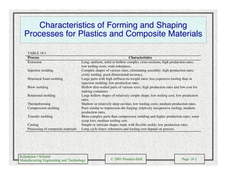
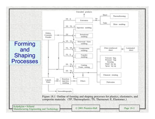
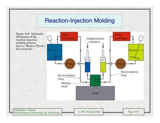
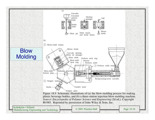
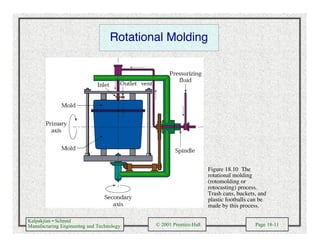
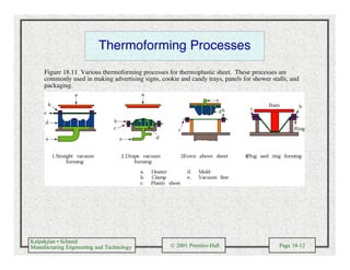
More Related Content
Similar to Forming and shaping plastics and composite materials (20)
Forming and shaping plastics and composite materials
- 2. Kalpakjian • Schmid
Manufacturing Engineering and Technology © 2001 Prentice-Hall Page 18-2
Characteristics of Forming and Shaping
Processes for Plastics and Composite Materials
TABLE 18.1
Process Characteristics
Extrusion Long, uniform, solid or hollow complex cross-sections; high production rates;
low tooling costs; wide tolerances.
Injection molding Complex shapes of various sizes, eliminating assembly; high production rates;
costly tooling; good dimensional accuracy.
Structural foam molding Large parts with high stiffness-to-weight ratio; less expensive tooling than in
injection molding; low production rates.
Blow molding Hollow thin-walled parts of various sizes; high production rates and low cost for
making containers.
Rotational molding Large hollow shapes of relatively simple shape; low tooling cost; low production
rates.
Thermoforming Shallow or relatively deep cavities; low tooling costs; medium production rates.
Compression molding Parts similar to impression-die forging; relatively inexpensive tooling; medium
production rates.
Transfer molding More complex parts than compression molding and higher production rates; some
scrap loss; medium tooling cost.
Casting Simple or intricate shapes made with flexible molds; low production rates.
Processing of composite materials Long cycle times; tolerances and tooling cost depend on process.
- 3. Kalpakjian • Schmid
Manufacturing Engineering and Technology © 2001 Prentice-Hall Page 18-3
Forming
and
Shaping
Processes
Figure 18.1 Outline of forming and shaping processes for plastics, elastomers, and
composite materials. (TP, Thermoplastic; TS, Thermoset; E, Elastomer.)
- 4. Kalpakjian • Schmid
Manufacturing Engineering and Technology © 2001 Prentice-Hall Page 18-4
Extruder
Figure 18.2 Schematic illustration of a typical extruder. Source: Encyclopedia of Polymer Science
and Engineering (2nd ed.). Copyright © 1985. Reprinted by permission of John Wiley & Sons, Inc.
- 5. Kalpakjian • Schmid
Manufacturing Engineering and Technology © 2001 Prentice-Hall Page 18-5
Sheet and Film Extrusion
Figure 18.3 Die geometry (coat-hanger die) for extruding sheet.
Source: Encyclopedia of Polymer Science and Engineering (2d ed.).
Copyright © 1985. Reprinted by permission of John Wiley & Sons, Inc.
Figure 18.4 Schematic illustration of the production of thin film and
plastic bags from tube first produced by an extruder and then blown by
air. Source: D.C. Miles and J.H. Briston, Polymer Technology, 1979.
Reproduced by permission of Chemical Publishing Co., Inc.
- 6. Kalpakjian • Schmid
Manufacturing Engineering and Technology © 2001 Prentice-Hall Page 18-6
Injection Molding
(c)
Figure 18.5 Injection molding with (a) plunger, (b) reciprocating rotating screw, (c) a typical part made from an
injection molding machine cavity, showing a number of parts made from one shot; note also mold features such as
sprues, runners, and gates.
- 7. Kalpakjian • Schmid
Manufacturing Engineering and Technology © 2001 Prentice-Hall Page 18-7
Examples of Injection Molding
Figure 18.6 Typical products made by
injection molding, including examples
of insert molding. Source: Plainfield
Molding Inc.
- 8. Kalpakjian • Schmid
Manufacturing Engineering and Technology © 2001 Prentice-Hall Page 18-8
Injection-Molding Machine
Figure 18.7 A 2.2-MN (250-ton) injection-molding machine. The tonnage is the force
applied to keep the dies closed during injection of molten plastic into the mold cavities.
Source: Courtesy of Cincinnati Milacron, Plastics Machinery Division.
- 9. Kalpakjian • Schmid
Manufacturing Engineering and Technology © 2001 Prentice-Hall Page 18-9
Reaction-Injection Molding
Figure 18.8 Schematic
illustration of the
reaction-injection
molding process.
Source: Modern Plastics
Encyclopedia.
- 10. Kalpakjian • Schmid
Manufacturing Engineering and Technology © 2001 Prentice-Hall Page 18-10
Blow
Molding
Figure 18.9 Schematic illustrations of (a) the blow-molding process for making
plastic beverage bottles, and (b) a three-station injection blow-molding machine.
Source: Encyclopedia of Polymer Science and Engineering (2d ed.). Copyright
©1985. Reprinted by permission of John Wiley & Sons, Inc.
- 11. Kalpakjian • Schmid
Manufacturing Engineering and Technology © 2001 Prentice-Hall Page 18-11
Rotational Molding
Figure 18.10 The
rotational molding
(rotomolding or
rotocasting) process.
Trash cans, buckets, and
plastic footballs can be
made by this process.
- 12. Kalpakjian • Schmid
Manufacturing Engineering and Technology © 2001 Prentice-Hall Page 18-12
Thermoforming Processes
Figure 18.11 Various thermoforming processes for thermoplastic sheet. These processes are
commonly used in making advertising signs, cookie and candy trays, panels for shower stalls, and
packaging.
- 13. Kalpakjian • Schmid
Manufacturing Engineering and Technology © 2001 Prentice-Hall Page 18-13
Compression Molding
Figure 18.12 Types of compression
molding, a process similar to forging: (a)
positive, (b) semipositive, and (c) flash.
The flash in part (c) has to be trimmed off.
(d) Die design for making a compression-
molded part with undercuts.
- 14. Kalpakjian • Schmid
Manufacturing Engineering and Technology © 2001 Prentice-Hall Page 18-14
Transfer Molding
Figure 18.13 Sequence of operations in transfer molding for thermosetting plastics. This process
is particularly suitable for intricate parts with varying wall thickness.
- 15. Kalpakjian • Schmid
Manufacturing Engineering and Technology © 2001 Prentice-Hall Page 18-15
Casting, Potting and Encapsulation
Figure 18.14 Schematic
illustration of (a) casting, (b)
potting, (c) encapsulation of
plastics.
- 16. Kalpakjian • Schmid
Manufacturing Engineering and Technology © 2001 Prentice-Hall Page 18-16
Calendering and Examples of Reinforced
Plastics
Figure 18.15 Schematic illustration
of calendering. Sheets produced by
this process are subsequently used
in thermoforming.
Figure 18.16 Reinforced- plastic
components for a Honda motorcycle.
The parts shown are front and rear
forks, a rear swingarm, a wheel, and
brake disks.
- 17. Kalpakjian • Schmid
Manufacturing Engineering and Technology © 2001 Prentice-Hall Page 18-17
Prepegs
Figure 18.17 (a) Manufacturing process for polymer-matrix composite. Source: T.W. Chou, R.L.
McCullough, and R.B. Pipes. (b) Boron-epoxy prepreg tape. Source: Avco Specialty
Materials/Textron.
(b)(a)
- 18. Kalpakjian • Schmid
Manufacturing Engineering and Technology © 2001 Prentice-Hall Page 18-18
Tape Laying
Figure 18.18 (a) Single-ply layup of
boron-epoxy tape for the horizontal
stabilizer for F-14 fighter aircraft. Source:
Grumman Aircraft Corporation. (b) A 10
axis computer-numerical-controlled tape-
laying system. This machine is capable of
laying up 75 mm and 150 mm (3 in. and 6
in.) wide tapes, on contours of up to ±30°
and at speeds of up to 0.5 m/s (1.7 ft/s).
Source: Courtesy of The Ingersoll Milling
Machine Company.
(a)
(b)
- 19. Kalpakjian • Schmid
Manufacturing Engineering and Technology © 2001 Prentice-Hall Page 18-19
Sheet Molding
Figure 18.19 The manufacturing
process for producing reinforced-
plastic sheets. The sheet is still
viscous at this stage; it can later be
shaped into various products. Source:
T. W. Chou, R. L. McCullough, and R.
B. Pipes.
- 20. Kalpakjian • Schmid
Manufacturing Engineering and Technology © 2001 Prentice-Hall Page 18-20
Examples of Molding Processes
Figure 18.20 (a) Vacuum-bag forming. (b) Pressure-bag forming. Source: T. H. Meister.
Figure 18.21 Manual
methods of processing
reinforced plastics: (a)
hand lay-up and (b)
spray-up. These
methods are also
called open-mold
processing.
- 21. Kalpakjian • Schmid
Manufacturing Engineering and Technology © 2001 Prentice-Hall Page 18-21
Filament Winding
(b)(a)
Figure 18.22 (a) Schematic illustration of the filament-winding process. (b) Fiberglass
being wound over aluminum liners, for slide-raft inflation vessels for the Boeing 767
aircraft. Source: Brunswick Corporation, Defense Division.
- 22. Kalpakjian • Schmid
Manufacturing Engineering and Technology © 2001 Prentice-Hall Page 18-22
Pultrusion
Figure 18.23 Schematic
illustration of the pultrusion
process.
- 23. Kalpakjian • Schmid
Manufacturing Engineering and Technology © 2001 Prentice-Hall Page 18-23
Design Modifications to Minimize Distortion
Figure 18.24 Examples of design
modifications to eliminate or
minimize distortion of plastic parts.
(a) Suggested design changes to
minimize distortion. Source: F.
Strasser. (b) Die design
(exaggerated) for extrusion of
square sections. Without this
design, product cross-sections
swell because of the recovery of
the material; this effect is known as
die swell. (c) Design change in a
rib, to minimize pull-in caused by
shrinkage during cooling. (d)
Stiffening the bottoms of thin
plastic containers by the bottoms of
thin plastic containers by doming-
this technique is similar to the
process used to make the bottoms
of aluminum beverage cans.
- 24. Kalpakjian • Schmid
Manufacturing Engineering and Technology © 2001 Prentice-Hall Page 18-24
Comparative Costs and Production Volumes
for Processing of Plastics
TABLE 18.2
Typical production volume, number of parts
Equipment
capital cost
Production
rate
Tooling
cost 10 10
2
10
3
10
4
10
5
10
6
10
7
Machining Medium Medium Low
Compression molding High Medium High
Transfer molding High Medium High
Injection molding High High High
Extrusion Medium High Low *
Rotational molding Low Low Low
Blow molding Medium Medium Medium
Thermoforming Low Low Low
Casting Low Very low Low
Forging High Low Medium
Foam molding High Medium Medium
Source: After R.L.E. Brown, Design and Manufacture of Plastic Parts. Copyright (c) 1980 by John Wiley & Sons, Inc.
Reprinted by permission of John Wiley & Sons, Inc.
*Continuous process.
- 25. Kalpakjian • Schmid
Manufacturing Engineering and Technology © 2001 Prentice-Hall Page 18-25
Economic Production Quantities for Various
Molding Methods
TABLE 18.3
Relative investment
required Relative Economic
Molding method Equipment Tooling
production
rate
production
quantity
Hand lay-up
Spray-up
Casting
Vacuum-bag molding
Compression-molded BMC
SIVIC and preform
Pressure-bag molding
Centrifugal casting
Filament winding
Pultrusion
Rotational molding
Injection molding
VL
L
M
M
H
H
H
H
H
H
H
VH
L
L
L
L
VH
VH
H
H
H
H
H
VH
L
L
L
VL
H
H
L
M
L
H
L
VH
VL
L
L
VL
H
H
L
M
L
H
M
VH