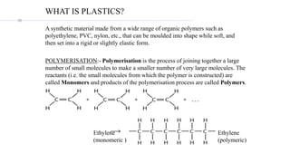
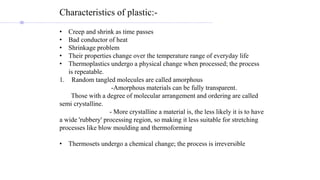
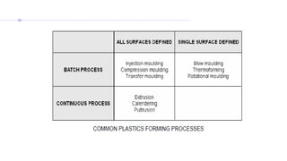
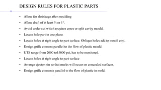
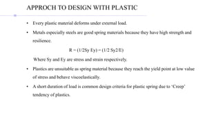
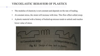
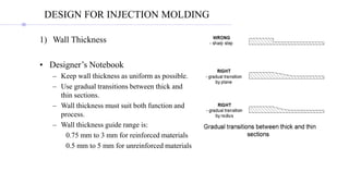
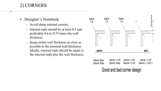
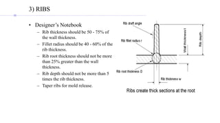
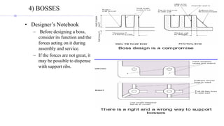
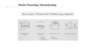
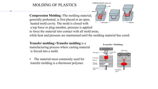
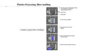
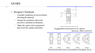
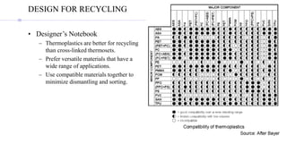
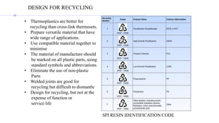
The document discusses various aspects of plastics design and manufacturing. It defines plastics and the polymerization process used to create them. It describes the main types of plastics as thermoplastics and thermosets, providing examples of each. It outlines key considerations for designing plastic parts, such as allowing for shrinkage, drafting angles, and hole placement. Finally, it discusses different plastic molding and forming processes like injection molding, blow molding, compression molding, and transfer molding.
2. WHAT IS PLASTICS?
A synthetic material made from a wide range of organic polymers such as
polyethylene, PVC, nylon, etc., that can be moulded into shape while soft, and
then set into a rigid or slightly elastic form.
POLYMERISATION:- Polymerisation is the process of joining together a large
number of small molecules to make a smaller number of very large molecules. The
reactants (i.e. the small molecules from which the polymer is constructed) are
called Monomers and products of the polymerisation process are called Polymers.
Ethylene
(monomeric )
Ethylene
(polymeric)
3.
4. • THERMOPLASTICS:- Describes a substance which becomes flexible when
heated and hardens on cooling with no change in its properties.
Example:-
Polyethylene: packaging, electrical insulation, milk and bottles, packaging film
Polypropylene: carpet fibers, automotive bumpers, microwave containers,
Polyvinyl chloride (PVC): electrical cables cover, credit cards, car panels.
Polystyrene: disposable spoons, forks, Styrofoam™
Acrylics (PMMA: polymethyl methacrylate): paints, fake fur, Flexiglass
Polyamide (nylon): textiles and fabrics, gears, bushing and washers, bearings
PET (polyethylene terephthalate): bottles for acidic foods like juices, food trays
PTFE (polytetrafluoroethylene): non-stick coating, Gore-Tex™ (raincoats), dental
floss
TYPES OF THERMOPLASTICS
5. • THERMOSETTING:-Thermosetting plastics are polymer materials which
are liquid or malleable at low temperatures, but which change irreversibly to
become hard at high temperatures.
Examples:
Polyurethanes: mattress, cushion, insulation, toys
Silicones: surgical gloves, oxygen masks in medical applications
joint seals
6. Characteristics of plastic:-
• Creep and shrink as time passes
• Bad conductor of heat
• Shrinkage problem
• Their properties change over the temperature range of everyday life
• Thermoplastics undergo a physical change when processed; the process
is repeatable.
1. Random tangled molecules are called amorphous
-Amorphous materials can be fully transparent.
Those with a degree of molecular arrangement and ordering are called
semi crystalline.
- More crystalline a material is, the less likely it is to have
a wide 'rubbery' processing region, so making it less suitable for stretching
processes like blow moulding and thermoforming
• Thermosets undergo a chemical change; the process is irreversible
7.
8. DESIGN RULES FOR PLASTIC PARTS
• Allow for shrinkage after moulding
• Allow draft of at least ½ or 1°.
• Avoid under cut which requires cores or split cavity mould.
• Locate hole part in one plane
• Locate holes at right angle to part surface. Oblique holes add to mould cost.
• Design grille element parallel to the flow of plastic mould
• UTS range from 2000 to15000 psi, has to be monitored.
• Locate holes at right angle to part surface
• Arrange ejector pin so that marks will occur on concealed surfaces.
• Design grille elements parallel to the flow of plastic in mold.
9. • Every plastic material deforms under external load.
• Metals especially steels are good spring materials because they have high strength and
resilience.
R = (1/2Sy Ey) = (1/2 Sy2/E)
Where Sy and Ey are stress and strain respectively.
• Plastics are unsuitable as spring material because they reach the yield point at low value
of stress and behave viscoelastically.
• A short duration of load is common design criteria for plastic spring due to ‘Creep’
tendency of plastics.
APPROCH TO DESIGN WITH PLASTIC
10. VISCOELASTIC BEHAVIOR OF PLASTICS
• The modulus of elasticity is not constant and depends on the rate of loading.
• At constant stress, the strain will increase with time. This flow effect called creep.
• A plastic material with a history of locked-up stresses tends to unlock and reaches
lower value of stress.
11. DESIGN FOR INJECTION MOLDING
1) Wall Thickness
• Designer’s Notebook
– Keep wall thickness as uniform as possible.
– Use gradual transitions between thick and
thin sections.
– Wall thickness must suit both function and
process.
– Wall thickness guide range is:
0.75 mm to 3 mm for reinforced materials
0.5 mm to 5 mm for unreinforced materials
12. 2) CORNERS
• Designer’s Notebook
– Avoid sharp internal corners.
– Internal radii should be at least 0.5 and
preferably 0.6 to 0.75 times the wall
thickness.
– Keep corner wall thickness as close as
possible to the nominal wall thickness.
Ideally, external radii should be equal to
the internal radii plus the wall thickness.
13. 3) RIBS
• Designer’s Notebook
– Rib thickness should be 50 - 75% of
the wall thickness.
– Fillet radius should be 40 - 60% of the
rib thickness.
– Rib root thickness should not be more
than 25% greater than the wall
thickness.
– Rib depth should not be more than 5
times the rib thickness.
– Taper ribs for mold release.
14. 4) BOSSES
• Designer’s Notebook
– Before designing a boss,
consider its function and the
forces acting on it during
assembly and service.
– If the forces are not great, it
may be possible to dispense
with support ribs.
16. MOLDING OF PLASTICS
Compression Molding:-The molding material,
generally preheated, is first placed in an open,
heated mold cavity. The mold is closed with
a top force or plug member, pressure is applied
to force the material into contact with all mold areas,
while heat and pressure are maintained until the molding material has cured.
Transfer molding:-Transfer molding is a
manufacturing process where casting material
is forced into a mold.
• The material most commonly used for
transfer molding is a thermoset polymer.
17. Plastics Processing: Blow molding
heated glass
3-piece mold
(a) The hollow piece of heated glass (parison)
is first created by a blow mold
(see text-book Fig 17.25)
(b) The mold is put together
(c) Plunger and hot air push the
glass up
(d) Hot air blows the glass out towards
the mold surface
(e) Mold comes apart, bottle is removed
heated glass
3-piece mold
(a) The hollow piece of heated glass (parison)
is first created by a blow mold
(see text-book Fig 17.25)
(b) The mold is put together
(c) Plunger and hot air push the
glass up
(d) Hot air blows the glass out towards
the mold surface
(e) Mold comes apart, bottle is removed
- similar to glass blow-molding -
19. Injection Molding: designing injection molds
1. molding directions number of inserts/cams required, if any
2. parting lines
3. parting planes by extending the parting line outwards
4. gating design where to locate the gate(s) ?
5. multiple cavity mold fix relative positions of the multiple parts
6. runners: flow of plastic into the cavity
7. sprue located:
8. functional parts of the mold
- ejection system: to eject the molded part
- systems to eject the solidified runners
- alignment rods: to keep all mold components aligned
20. LIVING HINGES
• Designer’s Notebook
– Gate position is all important.
– Flow must take place across the hinge.
– Beware of hesitation effects, weld lines, and
over packing.
– Provide a separate hinge cooling circuit.
– Flex the hinge immediately after ejection.
21. BEARINGS
• Designer’s Notebook
– For metal shafts, the harder and
smoother the better.
– Keep within the PV limit.
– Use specific grade data for K-
factor and PV limit.
– Except for slow-running and
lightly loaded bearings, verify
the design by testing prototypes.
22. GEARS
• Designer’s Notebook
– Consider conditions of service before
selecting the material.
– Design for symmetry and avoid
excessive variations in thickness.
– Make the center web symmetrical
and avoid ribs, spokes and holes.
23. DESIGN FOR RECYCLING
• Designer’s Notebook
– Thermoplastics are better for recycling
than cross-linked thermosets.
– Prefer versatile materials that have a
wide range of applications.
– Use compatible materials together to
minimize dismantling and sorting.
24. DESIGN FOR RECYCLING
• Thermoplastics are better for
recycling than cross-link thermosets.
• Prepare versatile material that have
wide range of applications.
• Use compatible material together to
minimise
• The material of manufacture should
be marked on all plastic parts, using
standard symbols and abbreviations
• Eliminate the use of non-plastic
Parts
• Welded joints are good for
recycling but difficult to dismantle
• Design for recycling, but not at the
expense of function or
service life
SPI RESIN IDENTIFICATION CODE