The document provides an overview of the casting process, including:
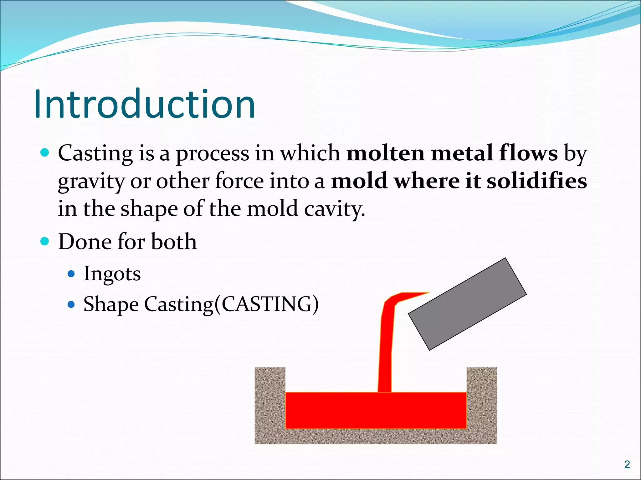
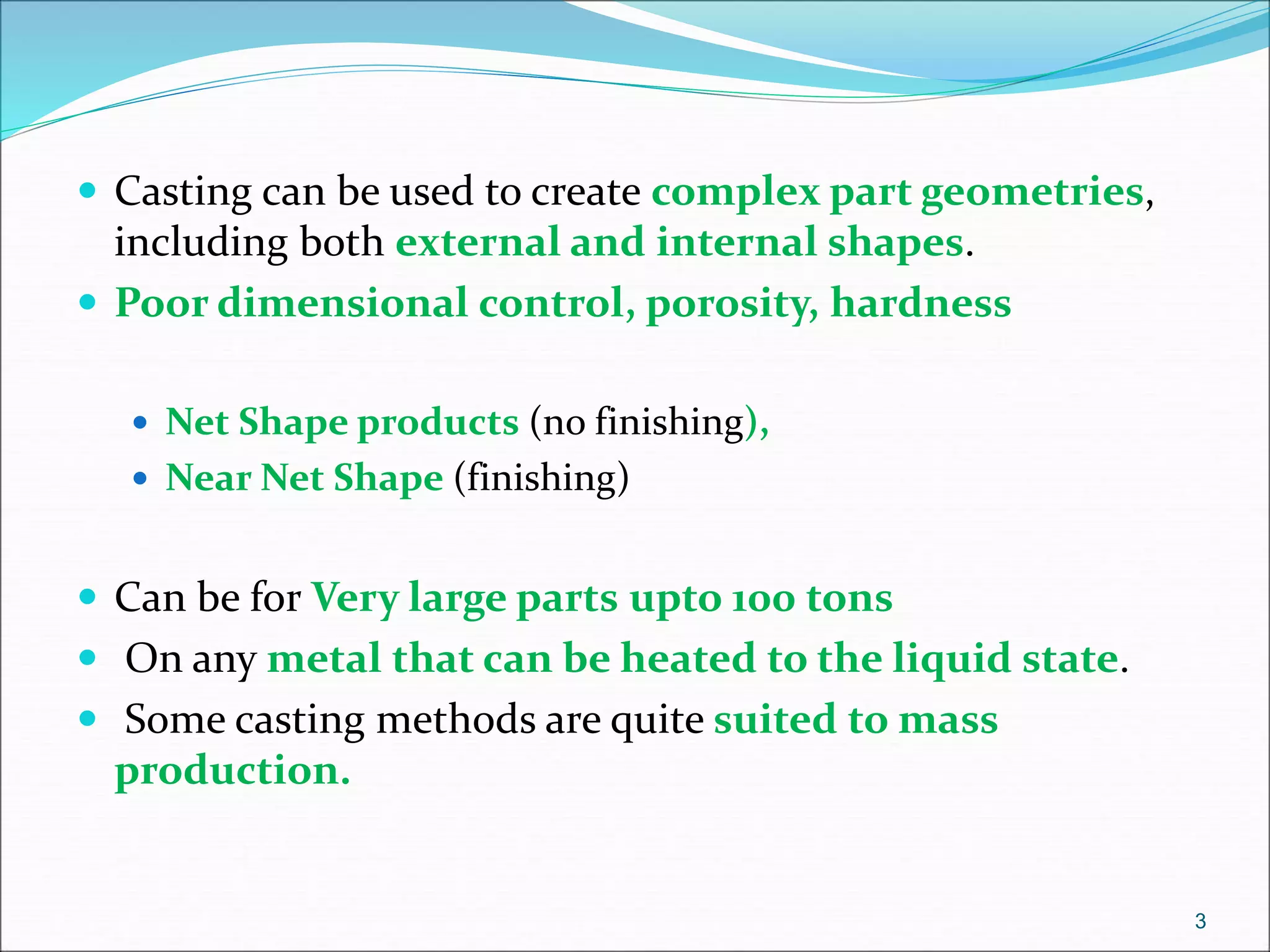
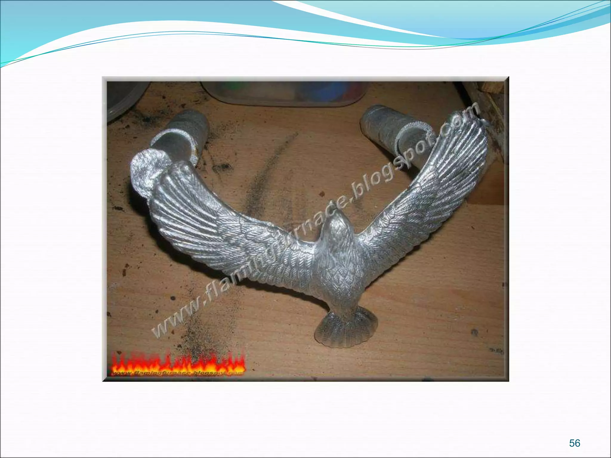
1. Casting involves pouring molten metal into a mold to solidify into the shape of the mold cavity. It can be used to create complex internal and external geometries.
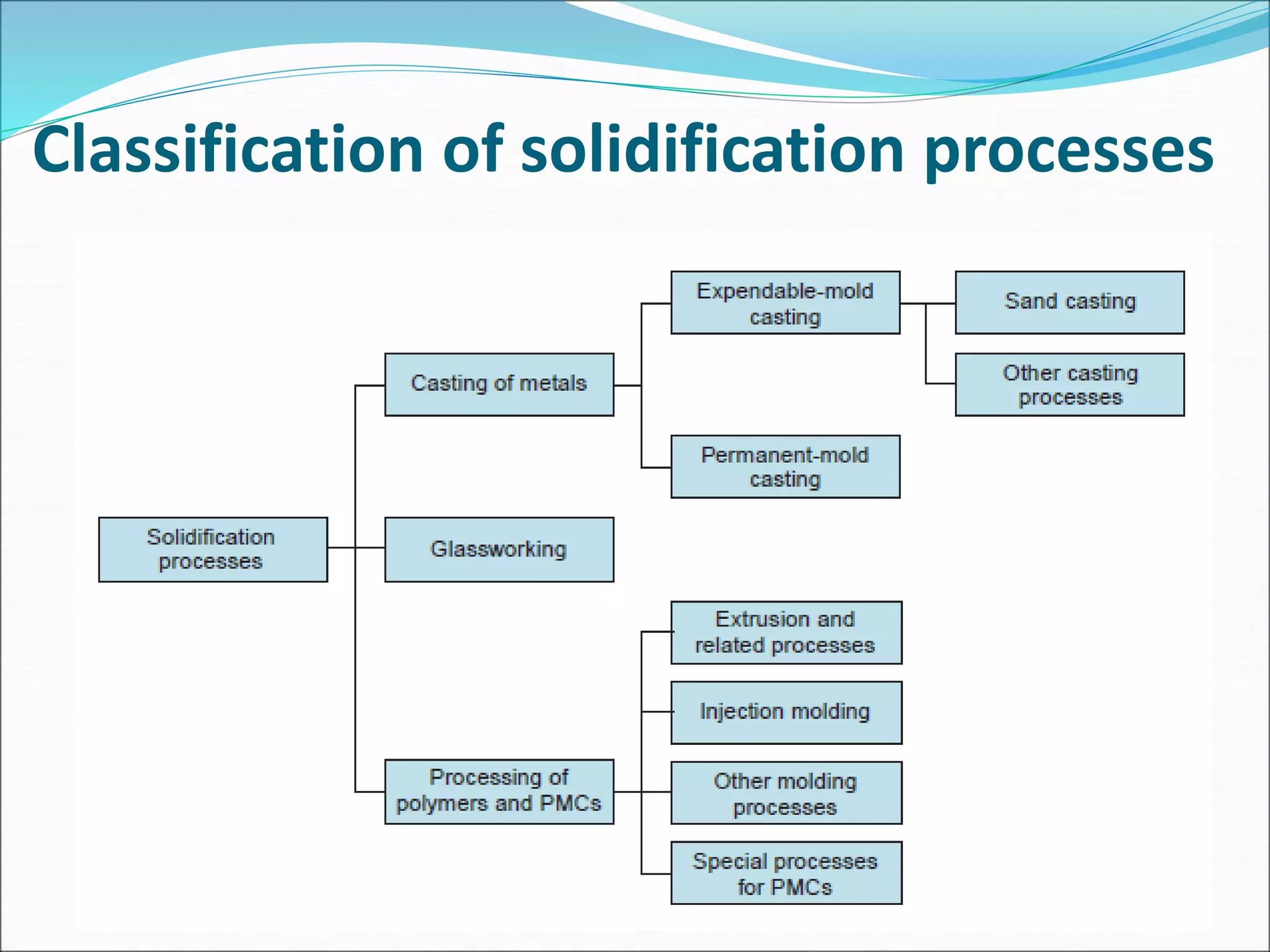
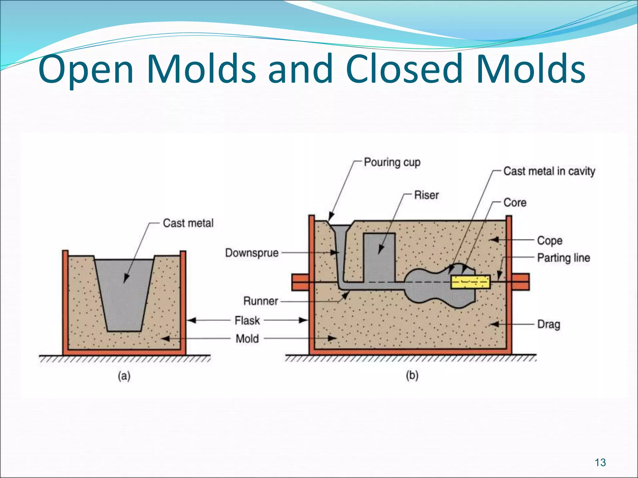
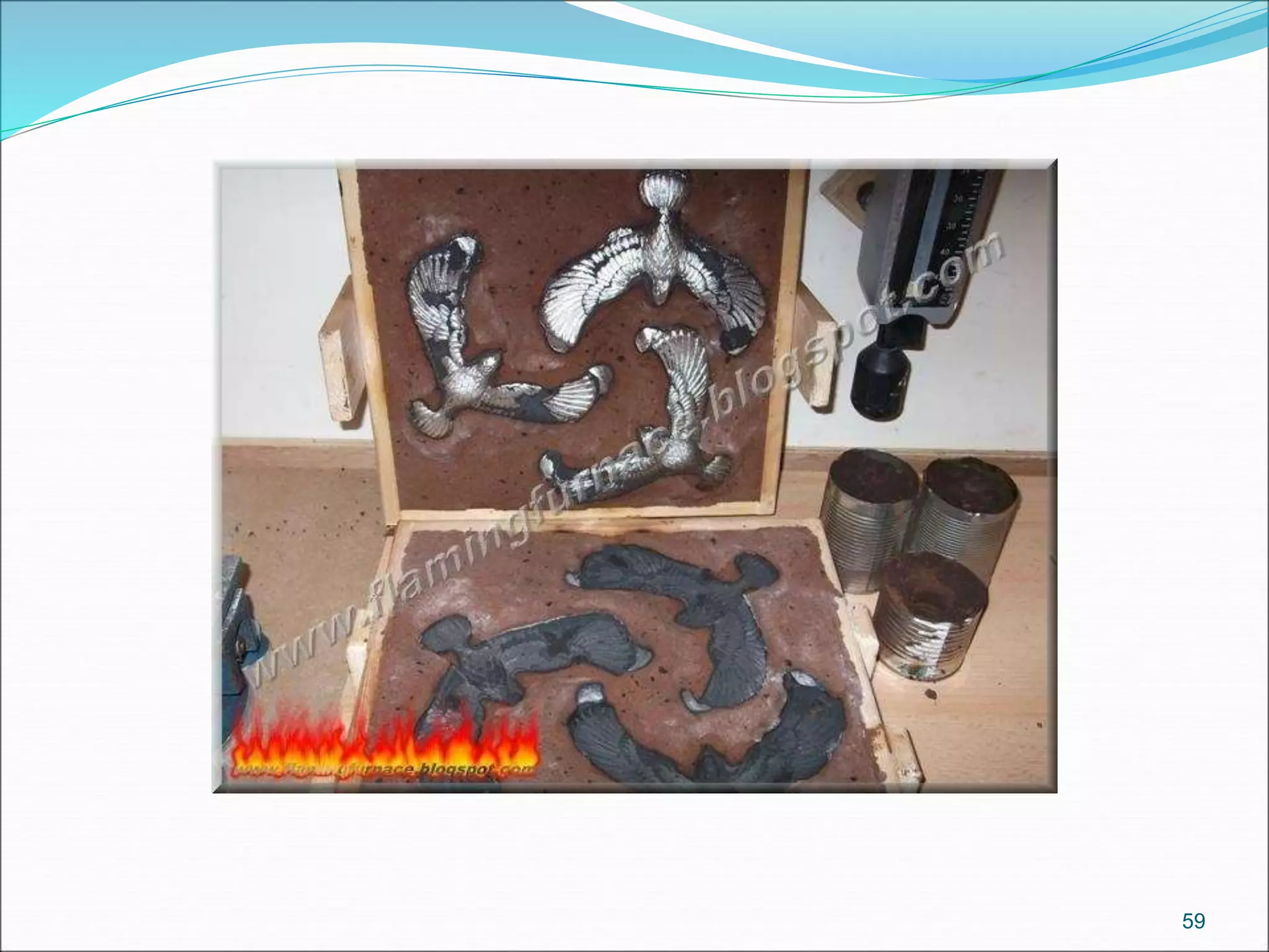
2. There are two main categories of casting processes - expendable mold processes using materials like sand, and permanent mold processes using reusable metal molds.
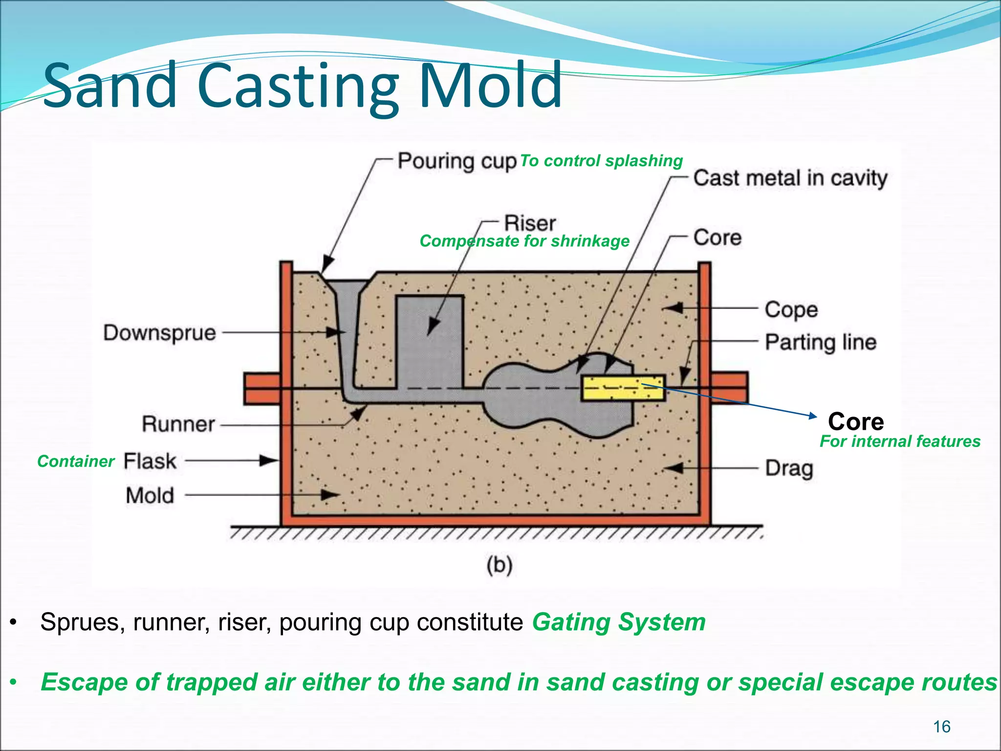
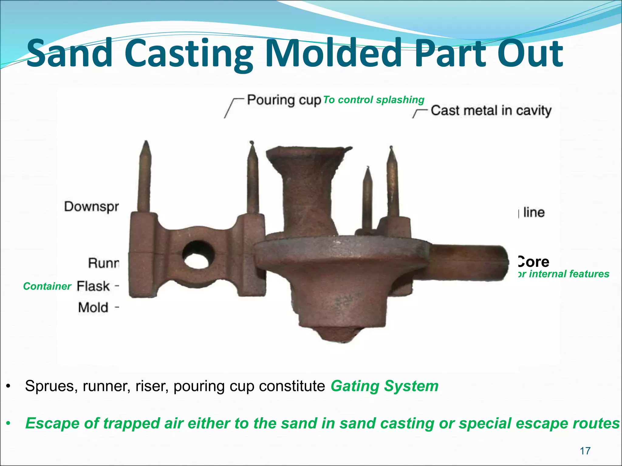
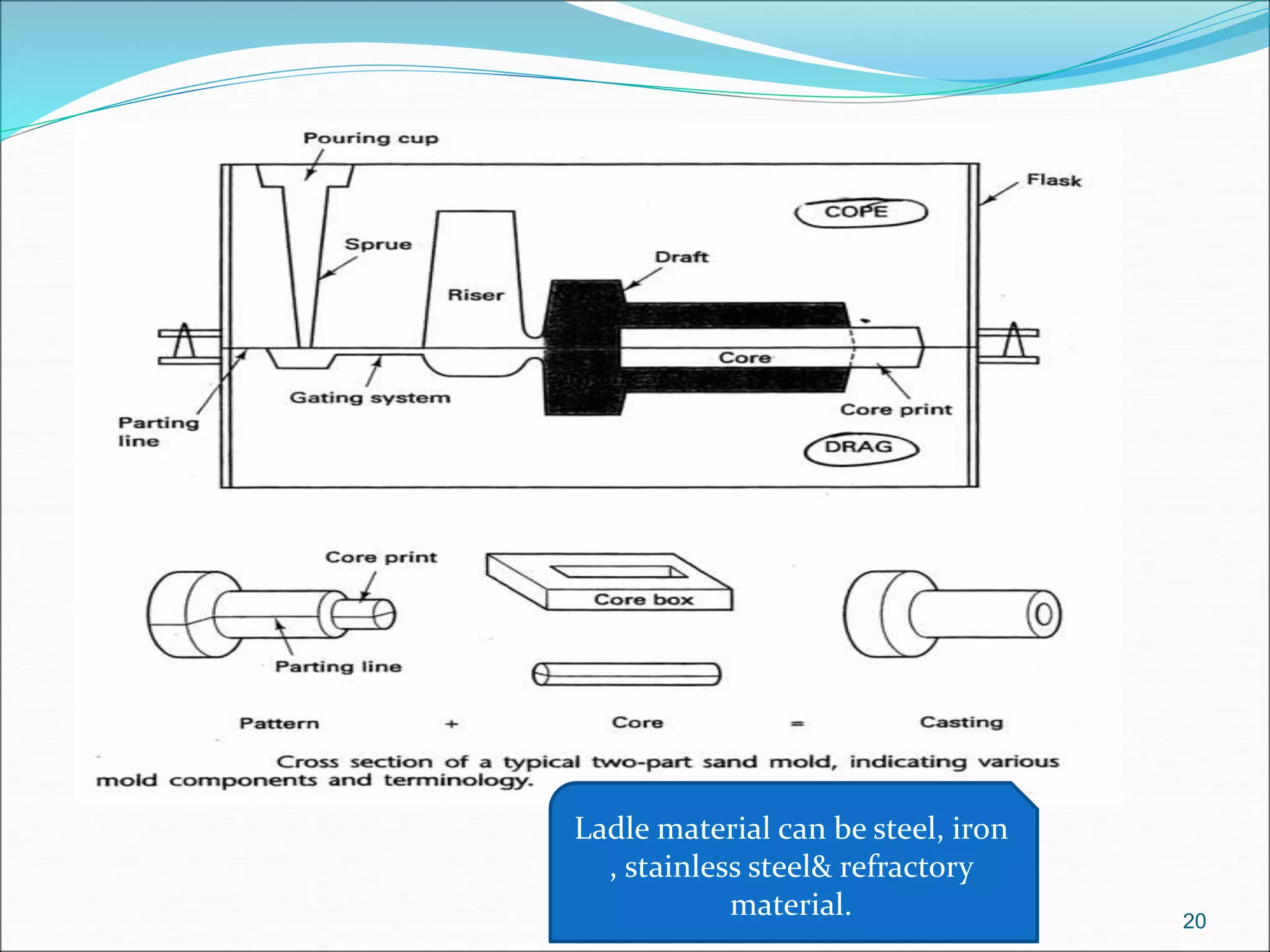
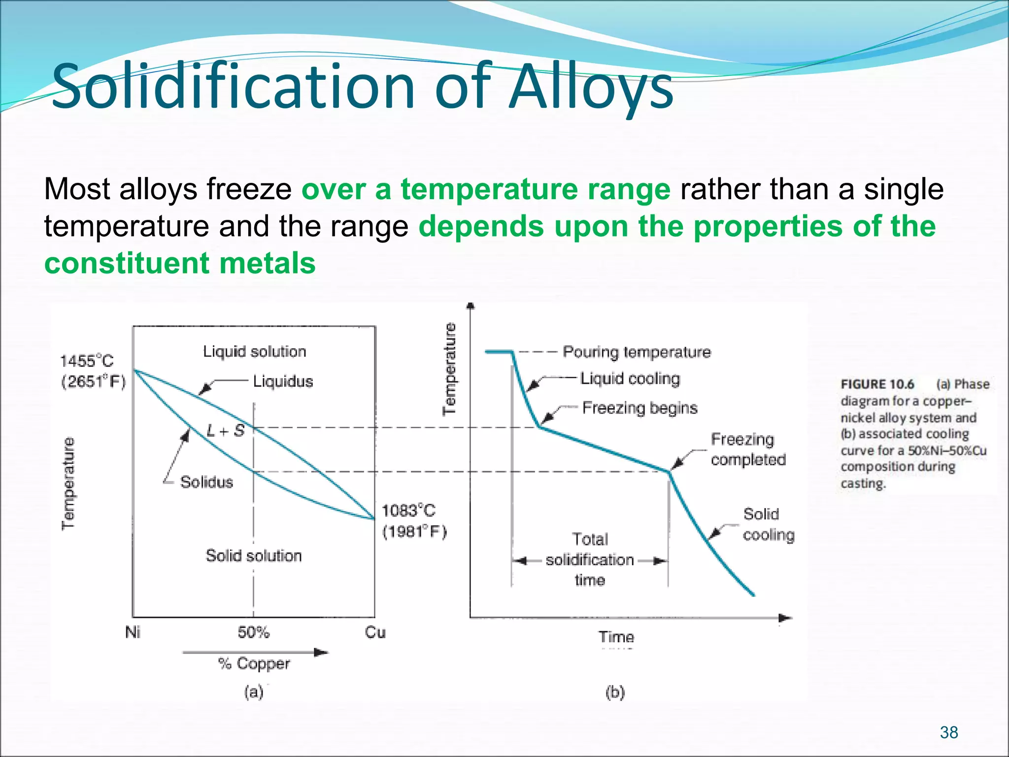
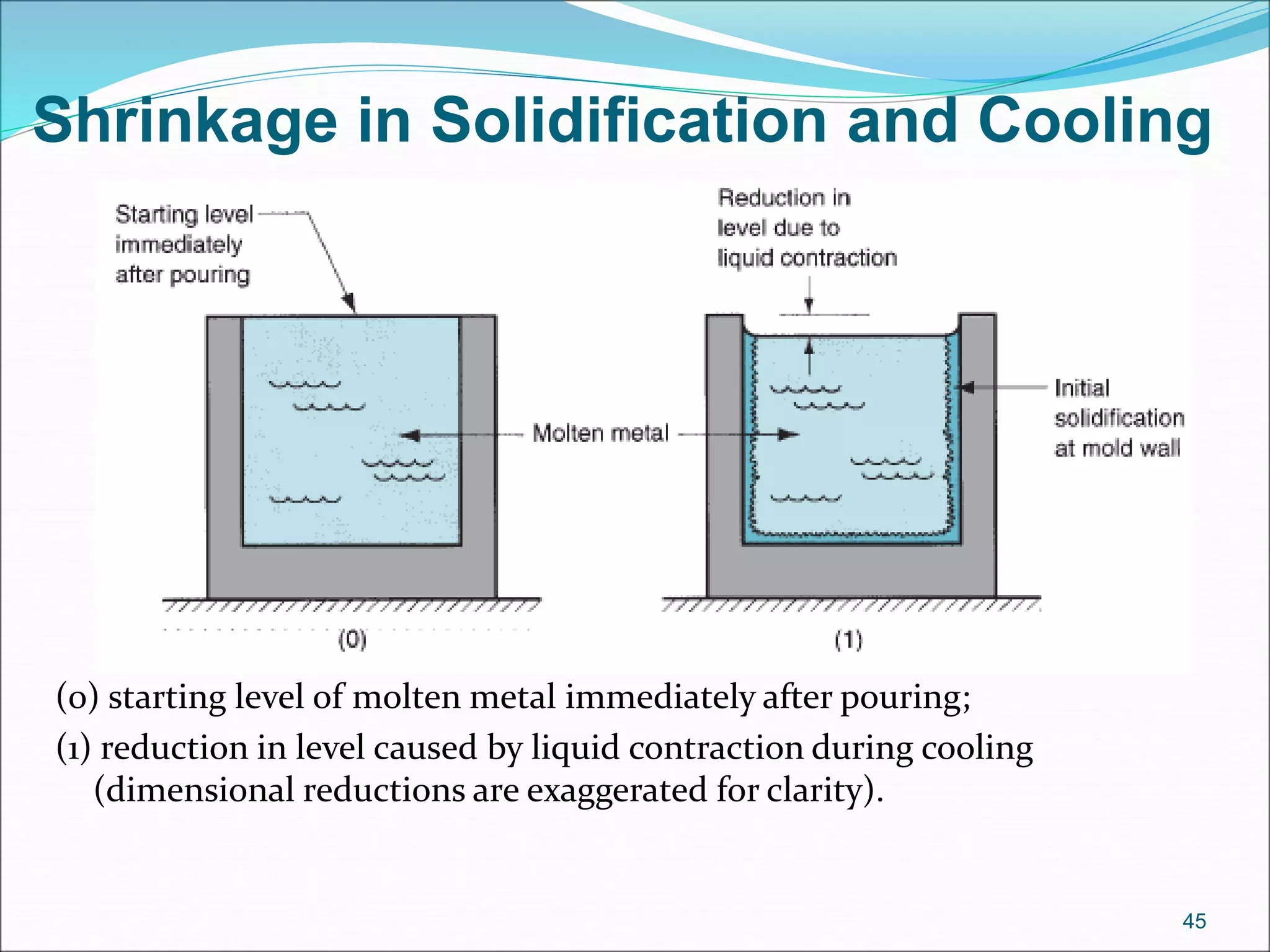
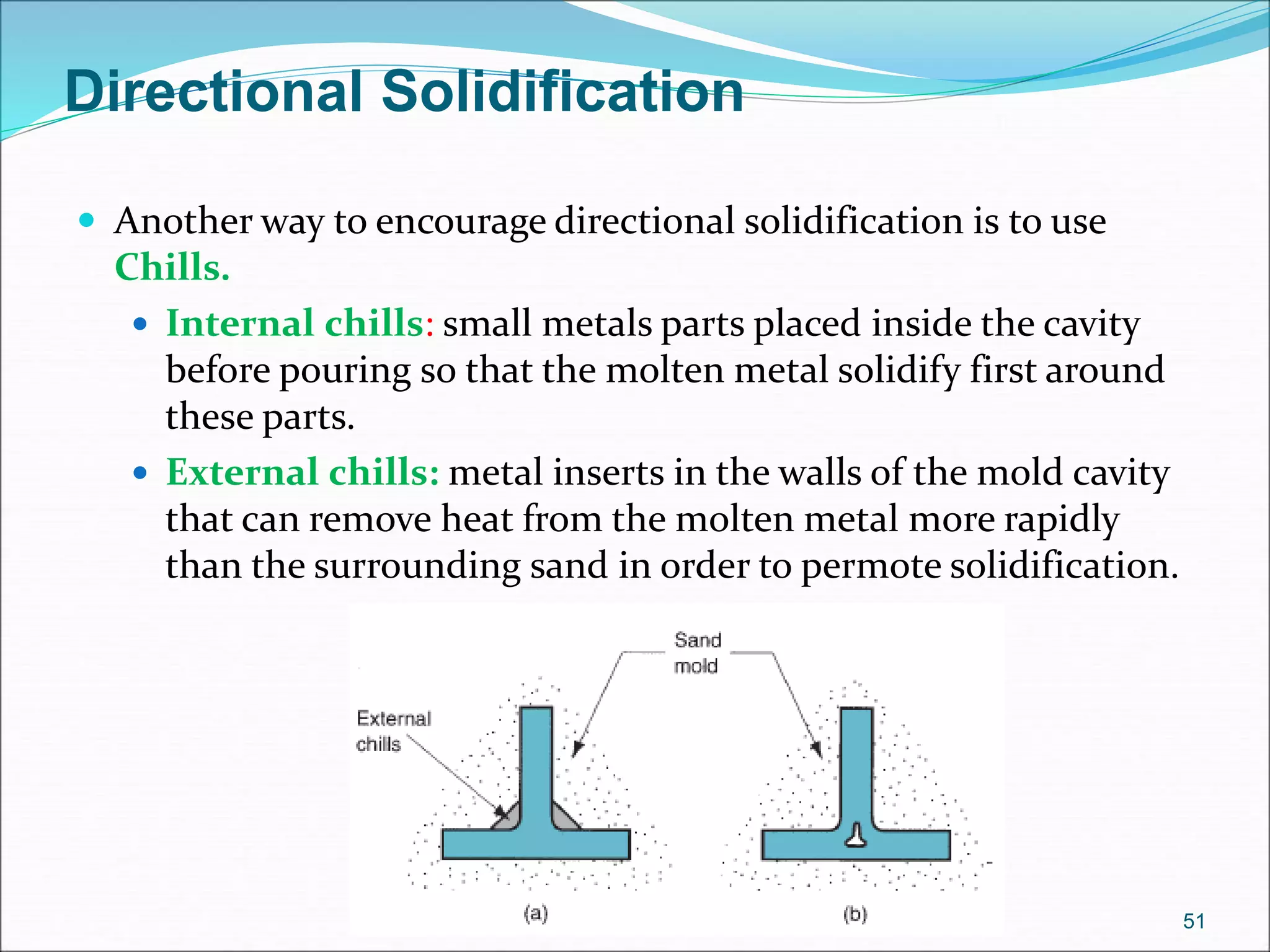
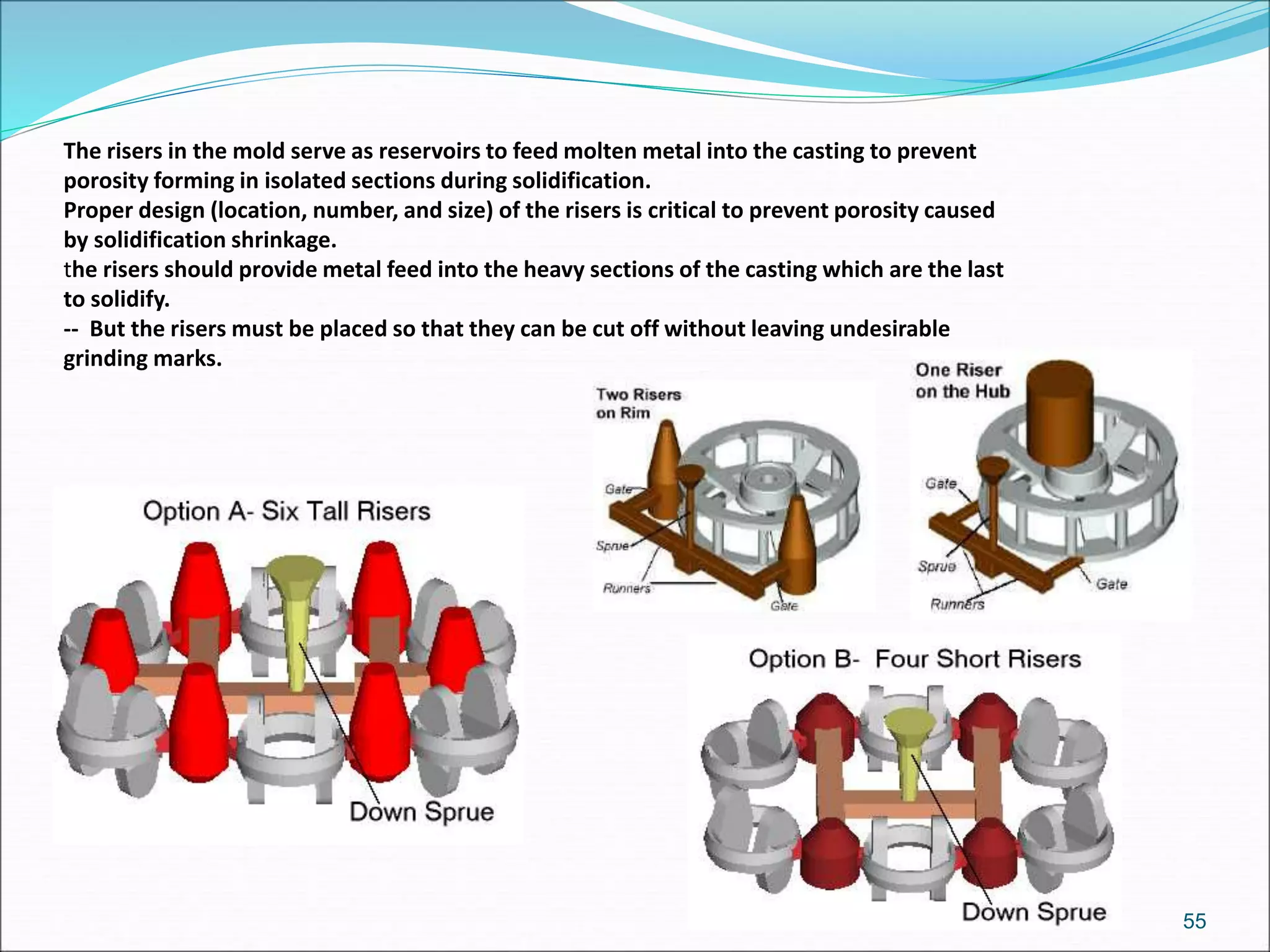
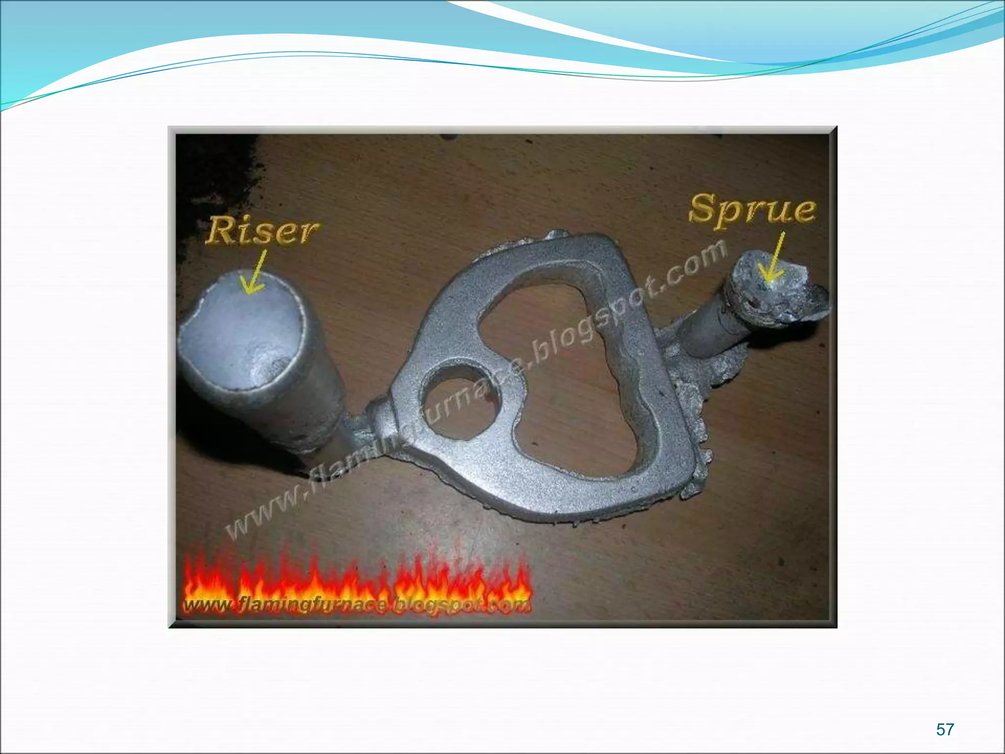
3. Key steps in casting include preparing the mold, pouring the molten metal, solidification as it cools and shrinks, and removing the finished casting from the mold. Proper design of gating, risers, and directional solidification is important to prevent defects.