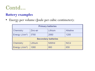
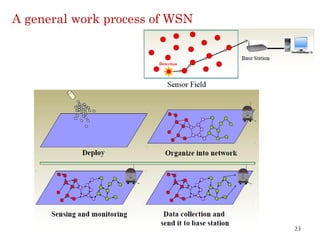
This document provides an overview of sensor networks and wireless sensor network architectures. It begins with an introduction to wireless sensor networks and their components. It then discusses the topics, challenges, and enabling technologies for WSNs. The document outlines the architecture of a sensor node and its goals. It provides examples of WSN applications and discusses sensor network deployment considerations. Finally, it addresses the design challenges, operational challenges, and required mechanisms for WSNs to meet their requirements.


![Contd…
• Out of band emission
– The inverse to adjacent channel suppression is the out of band
emission of a transmitter.
– To limit disturbance of other systems, or of the WSN itself in a
multichannel setup, the transmitter should produce little
transmission power
• Carrier sense and RSSI
– The precise semantics of this carrier sense signal depends on the
implementation.
– For example, the IEEE 802.15.4 standard [468] distinguishes the
following modes:
60](https://image.slidesharecdn.com/unitii-wsn21-210221101548/85/Sensor-Networks-Introduction-and-Architecture-60-320.jpg)
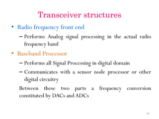
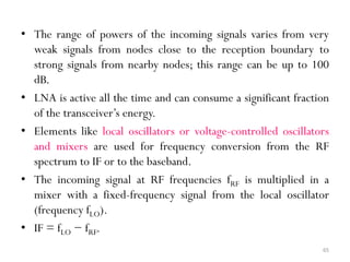
![• The Power Amplifier (PA) accepts upconverted signals from the IF or
baseband part and amplifies them for transmission over the antenna.
The Low Noise Amplifier (LNA) amplifies incoming signals up to
levels suitable for further processing without significantly reducing
the SNR [470].
64](https://image.slidesharecdn.com/unitii-wsn21-210221101548/85/Sensor-Networks-Introduction-and-Architecture-64-320.jpg)