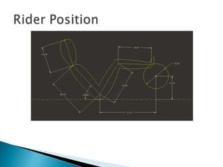
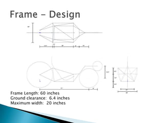
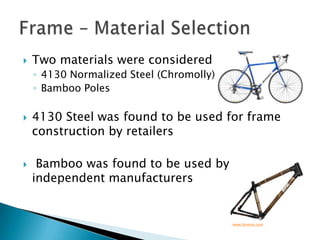
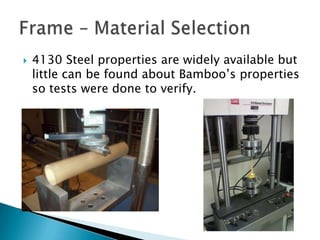
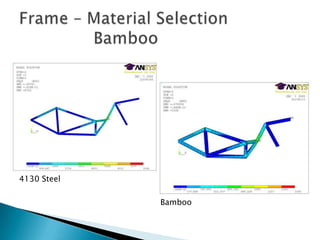
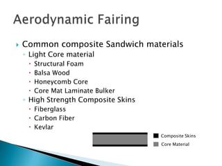
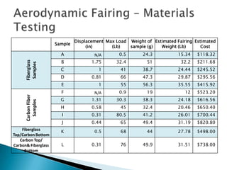
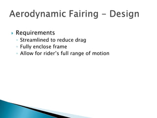
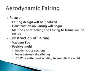
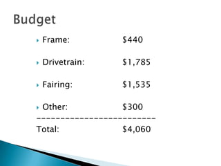
Single Rider Human Powered Vehicle Senior Project 1 Presentation
Design and construct,			  respective of constraints,  a single-rider recumbent fully faired human  powered vehicle.  Compete and win the 2010 ASME East Human Powered Vehicle Challenge.  Objective
Matthew Wright Team Manager/Seating Position/SteeringJames VanBiervlietFrameDante MucaroDrivetrain/Frame IntegrationsRich NelsonFairing Advisor:  		Dr. Lisa GregaCo-Advisors:  	Dr. Norman Asper				Dr. Manish PaliwalTeam Members
2010 ASME East Human Powered Vehicle Challenge“to provide an opportunity for engineering students to demonstrate application of sound engineering design principles toward the development of efficient, sustainable, and practical human-powered vehicles” May 7-9, 2010Central Connecticut State University
2010 ASME East Human Powered Vehicle ChallengeDesign EventSubmission of design report and presentationDrag EventDouble elimination tournament.6-.8 km trackEndurance Event2 ½ hoursMultiple Drivers
Design ConstraintsGoalsRoll Bar LoadingTop:						600 lbSide:						300 lbTurning Radius:				25 ftBraking Distance (15 mph-0 mph):	20 ftIncorporate Shoulder HarnessTop Speed in Drag Competition:	50 mphEndurance Average Speed:		30 mph
Project ManagementMatthew Wright
Ensure that the project team completes the task at handDevelop the plan with the team and manages the team’s performance of tasksMake sure the project is delivered in budget, on schedule, and is practical Project Management
Google CalendarCoordinate schedules for meetingsInform team members of project deadlinesProject Management
DropboxOnline file storage serviceAll team members and advisorsProject websitetcnjhumanpowered.blogspot.comEnable public to be informed and track progress of the projectProject Management
Project Management
Rider Position & Steering SystemMatthew Wright
Be secured safely within the vehicleComfortableProvide power to the crankRider Position
Rider Position
Rider Position
Above Seat Steering vs. Under Seat Steering			              (rps.info)Steering System
Above seat steering system chosenHead tube too far away from rider for standard straight bicycle handlebarsSolid bent handlebars (Tiller steering)Universal Joint with steering column to handlebarsEnables easy entrance and    exit of vehicleSteering System
Steering System
Frame James VanBiervliet
Withstand a 600 lb top load at a 12 degree angle towards rear of vehicleSupport 300 lb loading directly to the side of the vehicleAll team membersmust fit insideFrame - Constraintshttp://www.wind-water.nl/rec_build_n.html
Original designs included one under seat support and two converging supports on the side of the seatPedals were located behind the front wheel Frame - Designhttp://bikemart.com
Frame - DesignFrame Length:  75 inchesTotal width:  20 inchesGround clearance:  5 inches
Second frame design incorporated a tub like styleProvides anchor points for fairingUsed a pedal set above the front wheel to reduce overall length lengthFrame - Design
Frame - DesignFrame Length: 60 inchesGround clearance:  6.4 inchesMaximum width:  20 inches
Ultimately chose the second designKept length to a minimumProvided better support for the fairingGave driver the most leg roomFrame - Design
Needs to be strong and durableSince the goal is speed, lightweight materials are essentialWanted a material that would minimize cost without sacrificing safetyFrame - Material Selection
Two materials were considered4130 Normalized Steel (Chromolly)Bamboo Poles4130 Steel was found to be used for frame construction by retailers Bamboo was found to be used by independent manufacturersFrame – Material Selectionwww.bmeres.com
4130 Steel properties are widely available but little can be found about Bamboo’s properties so tests were done to verify.Frame – Material Selection
Frame – Material Selectionhttp://bambus.rwth-aachen.de/http://www.tropicaltikis.com/
Frame – Material Selection		  Side Loading4130 SteelBamboo
Frame – Material Selection		  Bamboo4130 SteelBamboo
Frame – Material Selectionhttp://www.engineersedge.com/Bamboo was ultimately chosen based on the significant difference in cost and weight.
Drivetrain& Frame Integrations Dante Mucaro
Drivetrain RequirementsHigh range of gears for acceleration runs and endurance testingDurableEasily servicedUtilize standard bicycle drivetrain components for cost2 wheel layoutMinimize weight
Wheel Choices2 wheeled vehicleFront or rear drive wheel:Image Sourced: http://www.rose-hulman.edu/hpv/Image Sourced: http://img.alibaba.com/photo/10798856/Recumbent_Bike.jpg
Wheel selection	Rear drive wheel system selectedWheel selection:Maximize acceleration and overall speed20” front wheelCompactLightweight26” drive wheelMaximize developmentAdaptable hubs
Drivetrain System SelectionRequirements:Wide gear rangeDurableInexpensiveAdaptableEasily servicedThree optionsChain driveShaft driveBelt drive
Option 1: Chain DriveCranksetcrank arms chainringsbottom bracketCassetteDerailleurCassetteChainImage Sourced: http://en.wikipedia.org/wiki/File:Derailleur_Bicycle_Drivetrain.svg
Option 2: Shaft DriveBevel gear replaces chainringsDriveshaft replaces chainRear bevel	gearHub GearsScreen Capture Source: http://www.dynamicbicycles.com/
Option 3: Belt DriveSingle front gearSingle rear gearToothed belt 	replaces chainGearing through hubImage Source: http://paketabike.files.wordpress.com/2009/08/wac_corp_beltdrive2.jpg
Decision: Chain DriveGearing:Top speed and accelerationMany available gearsHigh speed: High front-to-rear ratioQuick start: Low front-to-rear ratioAcceleration: Proper gear ratio spacing
Sprocket optionsStandard road bike drivetrainTen speed cassetteTwo speed cranksetModify to achieve proper gear spacing while getting a higher top gear ratioUse two speed crankIntegrate second chain system with a high to low sprocket for higher overall ratios pedal-to-crank20 overall speeds
Layout
Selected SprocketsFront crank chainring: 55TDrive chainring: 40TDriven chainrings: 34/50TCassette: 11-28T11, 12, 13, 14, 15, 17, 19, 22, 25, 28
Gear rangesHighest overall gear ratio:55T-40T translated to 50T-11T43.5mph at a pedaling rate of 90RPM42.542ft of development/ revolutionDrive ratio: 6.25:1Lowest overall gear ratio:55T-40T translated to 34T-28T11.6mph at a pedaling rate of 90RPM11.365ft of development/ revolutionDrive ratio: 1.67:1
Braking System15-0 mph braking distance:<20ftStopping more mass than in typical bicycle applicationOptionsRim BrakesDisc BrakesHydraulic DiscMechanical DiscStrong consideration to DH brakes
Brake SelectionMechanical disc brakesAdvantages:Provide greater stopping power than most competitively priced rim brakesMuch less expensive than hydraulic disc brakesNo risk of boiling in high heat applicationsCan be adapted well to a 26” wheel hubDisadvantages:Front 20” wheel must be custom built with a disc brake compatible hub
Front Crank Arm DesignAdjustable for different ridersWithstand both torsional and axial cyclic loading with minimal deflectionHouse bottom bracket for cranksetHouse headset for steering systemIntegrate into bamboo frameLightweight
Front Crank Adjustable Arm
Goals for Senior Project IIConstruct adjustable crank armDetermine ideal method to mount drive and driven sprockets beneath rider seatObtain all necessary drivetrain componentsConstruct custom front wheelConstruct chain guides for 55-40T chain extensionDevelop lightweight kickstand to be integrated into fairing/ tub frame assembly
Aerodynamic FairingRich Nelson
RulesRequire frontal fairing, tail box, or full fairingPurpose:To Reduce aero dynamic dragWhen riding over 18 mph, drag accounts for over 80% of the forces acting to slow an unfaired bike. 1GoalsReduce Aerodynamic DragFully Encompass Frame and RiderStiffLightMinimize CostAerodynamic FairingGross, Albert C., Chester R. Kyle, and Douglas J. Malewiki. Aerodynamics of human-powered land vehicles. Rep. Professional Engineering, 2004.
Composite Sandwich ConstructionHigh stiffness-to-weight ratio compared to standard coreless composite laminate 2Acts similarly to an I-beamAerodynamic FairingVinson, Jack R. Behavior of sandwich structures of isotropic and composite materials. Lancaster, Pa: Technomic Pub. Co., 1999.
Common composite Sandwich materialsLight Core materialStructural FoamBalsa WoodHoneycomb CoreCore Mat Laminate BulkerHigh Strength Composite SkinsFiberglassCarbon FiberKevlarAerodynamic FairingComposite SkinsCore Material
Aerodynamic Fairing – Materials Testing
Construction of Samples12”x3.5” with positive camberVacuum Bag ConstructionCreates strong bond between core and skinRemoves excess resinPresses samples onto the formAerodynamic Fairing – Materials Testing
Vacuum Bag LayupAerodynamic Fairing – Materials Testing
Samples in Vacuum BagAerodynamic Fairing – Materials TestingUntrimmed Completed Samples
Wetted out with epoxy resin.Samples Tested as simply supported beamsInformation RecordedMaximum DeflectionMaximum Load SupportedWeight of SamplesAerodynamic Fairing – Materials Testing
Aerodynamic Fairing – Materials Testing
ConclusionsCore¼” Diviney Cell Foam (2x1/8” for tight contoured areas)$50 more expensive Than 1/8” Foam for the whole fairingHeld the most weight in all cases22-30% Heavier than 1/8” Foam but 60-77% StrongerCompositeFiberglassheld 10-20% less weight than Carbon Fiber~4lb heavier for whole fairing.Able to Deflect 40%-60% more than Carbon Before Breaking2-3 time less expensive then Carbon FiberAerodynamic Fairing – Materials Testing
RequirementsStreamlined to reduce dragFully enclose frameAllow for rider’s full range of motionAerodynamic Fairing - Design
2-D Sketch of Fairing DesignAerodynamic Fairing - Design
3-D Model Made from 2-D SketchAerodynamic Fairing - Design
Aerodynamic Fairing - DesignDesigns will be tested using
Computational Fluid Dynamics
Wind Tunnel Testing
Used to analyze
Aerodynamic Drag

Senior Project1presentation

  • 1.
    Single Rider HumanPowered Vehicle Senior Project 1 Presentation
  • 2.
    Design and construct, respective of constraints, a single-rider recumbent fully faired human powered vehicle. Compete and win the 2010 ASME East Human Powered Vehicle Challenge. Objective
  • 3.
    Matthew Wright TeamManager/Seating Position/SteeringJames VanBiervlietFrameDante MucaroDrivetrain/Frame IntegrationsRich NelsonFairing Advisor: Dr. Lisa GregaCo-Advisors: Dr. Norman Asper Dr. Manish PaliwalTeam Members
  • 4.
    2010 ASME EastHuman Powered Vehicle Challenge“to provide an opportunity for engineering students to demonstrate application of sound engineering design principles toward the development of efficient, sustainable, and practical human-powered vehicles” May 7-9, 2010Central Connecticut State University
  • 5.
    2010 ASME EastHuman Powered Vehicle ChallengeDesign EventSubmission of design report and presentationDrag EventDouble elimination tournament.6-.8 km trackEndurance Event2 ½ hoursMultiple Drivers
  • 6.
    Design ConstraintsGoalsRoll BarLoadingTop: 600 lbSide: 300 lbTurning Radius: 25 ftBraking Distance (15 mph-0 mph): 20 ftIncorporate Shoulder HarnessTop Speed in Drag Competition: 50 mphEndurance Average Speed: 30 mph
  • 7.
  • 8.
    Ensure that theproject team completes the task at handDevelop the plan with the team and manages the team’s performance of tasksMake sure the project is delivered in budget, on schedule, and is practical Project Management
  • 9.
    Google CalendarCoordinate schedulesfor meetingsInform team members of project deadlinesProject Management
  • 10.
    DropboxOnline file storageserviceAll team members and advisorsProject websitetcnjhumanpowered.blogspot.comEnable public to be informed and track progress of the projectProject Management
  • 11.
  • 12.
    Rider Position &Steering SystemMatthew Wright
  • 13.
    Be secured safelywithin the vehicleComfortableProvide power to the crankRider Position
  • 14.
  • 15.
  • 16.
    Above Seat Steeringvs. Under Seat Steering (rps.info)Steering System
  • 17.
    Above seat steeringsystem chosenHead tube too far away from rider for standard straight bicycle handlebarsSolid bent handlebars (Tiller steering)Universal Joint with steering column to handlebarsEnables easy entrance and exit of vehicleSteering System
  • 18.
  • 19.
  • 20.
    Withstand a 600lb top load at a 12 degree angle towards rear of vehicleSupport 300 lb loading directly to the side of the vehicleAll team membersmust fit insideFrame - Constraintshttp://www.wind-water.nl/rec_build_n.html
  • 21.
    Original designs includedone under seat support and two converging supports on the side of the seatPedals were located behind the front wheel Frame - Designhttp://bikemart.com
  • 22.
    Frame - DesignFrameLength: 75 inchesTotal width: 20 inchesGround clearance: 5 inches
  • 23.
    Second frame designincorporated a tub like styleProvides anchor points for fairingUsed a pedal set above the front wheel to reduce overall length lengthFrame - Design
  • 24.
    Frame - DesignFrameLength: 60 inchesGround clearance: 6.4 inchesMaximum width: 20 inches
  • 25.
    Ultimately chose thesecond designKept length to a minimumProvided better support for the fairingGave driver the most leg roomFrame - Design
  • 26.
    Needs to bestrong and durableSince the goal is speed, lightweight materials are essentialWanted a material that would minimize cost without sacrificing safetyFrame - Material Selection
  • 27.
    Two materials wereconsidered4130 Normalized Steel (Chromolly)Bamboo Poles4130 Steel was found to be used for frame construction by retailers Bamboo was found to be used by independent manufacturersFrame – Material Selectionwww.bmeres.com
  • 28.
    4130 Steel propertiesare widely available but little can be found about Bamboo’s properties so tests were done to verify.Frame – Material Selection
  • 29.
    Frame – MaterialSelectionhttp://bambus.rwth-aachen.de/http://www.tropicaltikis.com/
  • 30.
    Frame – MaterialSelection Side Loading4130 SteelBamboo
  • 31.
    Frame – MaterialSelection Bamboo4130 SteelBamboo
  • 32.
    Frame – MaterialSelectionhttp://www.engineersedge.com/Bamboo was ultimately chosen based on the significant difference in cost and weight.
  • 33.
  • 34.
    Drivetrain RequirementsHigh rangeof gears for acceleration runs and endurance testingDurableEasily servicedUtilize standard bicycle drivetrain components for cost2 wheel layoutMinimize weight
  • 35.
    Wheel Choices2 wheeledvehicleFront or rear drive wheel:Image Sourced: http://www.rose-hulman.edu/hpv/Image Sourced: http://img.alibaba.com/photo/10798856/Recumbent_Bike.jpg
  • 36.
    Wheel selection Rear drivewheel system selectedWheel selection:Maximize acceleration and overall speed20” front wheelCompactLightweight26” drive wheelMaximize developmentAdaptable hubs
  • 37.
    Drivetrain System SelectionRequirements:Widegear rangeDurableInexpensiveAdaptableEasily servicedThree optionsChain driveShaft driveBelt drive
  • 38.
    Option 1: ChainDriveCranksetcrank arms chainringsbottom bracketCassetteDerailleurCassetteChainImage Sourced: http://en.wikipedia.org/wiki/File:Derailleur_Bicycle_Drivetrain.svg
  • 39.
    Option 2: ShaftDriveBevel gear replaces chainringsDriveshaft replaces chainRear bevel gearHub GearsScreen Capture Source: http://www.dynamicbicycles.com/
  • 40.
    Option 3: BeltDriveSingle front gearSingle rear gearToothed belt replaces chainGearing through hubImage Source: http://paketabike.files.wordpress.com/2009/08/wac_corp_beltdrive2.jpg
  • 41.
    Decision: Chain DriveGearing:Topspeed and accelerationMany available gearsHigh speed: High front-to-rear ratioQuick start: Low front-to-rear ratioAcceleration: Proper gear ratio spacing
  • 42.
    Sprocket optionsStandard roadbike drivetrainTen speed cassetteTwo speed cranksetModify to achieve proper gear spacing while getting a higher top gear ratioUse two speed crankIntegrate second chain system with a high to low sprocket for higher overall ratios pedal-to-crank20 overall speeds
  • 43.
  • 44.
    Selected SprocketsFront crankchainring: 55TDrive chainring: 40TDriven chainrings: 34/50TCassette: 11-28T11, 12, 13, 14, 15, 17, 19, 22, 25, 28
  • 45.
    Gear rangesHighest overallgear ratio:55T-40T translated to 50T-11T43.5mph at a pedaling rate of 90RPM42.542ft of development/ revolutionDrive ratio: 6.25:1Lowest overall gear ratio:55T-40T translated to 34T-28T11.6mph at a pedaling rate of 90RPM11.365ft of development/ revolutionDrive ratio: 1.67:1
  • 46.
    Braking System15-0 mphbraking distance:<20ftStopping more mass than in typical bicycle applicationOptionsRim BrakesDisc BrakesHydraulic DiscMechanical DiscStrong consideration to DH brakes
  • 47.
    Brake SelectionMechanical discbrakesAdvantages:Provide greater stopping power than most competitively priced rim brakesMuch less expensive than hydraulic disc brakesNo risk of boiling in high heat applicationsCan be adapted well to a 26” wheel hubDisadvantages:Front 20” wheel must be custom built with a disc brake compatible hub
  • 48.
    Front Crank ArmDesignAdjustable for different ridersWithstand both torsional and axial cyclic loading with minimal deflectionHouse bottom bracket for cranksetHouse headset for steering systemIntegrate into bamboo frameLightweight
  • 49.
  • 50.
    Goals for SeniorProject IIConstruct adjustable crank armDetermine ideal method to mount drive and driven sprockets beneath rider seatObtain all necessary drivetrain componentsConstruct custom front wheelConstruct chain guides for 55-40T chain extensionDevelop lightweight kickstand to be integrated into fairing/ tub frame assembly
  • 51.
  • 52.
    RulesRequire frontal fairing,tail box, or full fairingPurpose:To Reduce aero dynamic dragWhen riding over 18 mph, drag accounts for over 80% of the forces acting to slow an unfaired bike. 1GoalsReduce Aerodynamic DragFully Encompass Frame and RiderStiffLightMinimize CostAerodynamic FairingGross, Albert C., Chester R. Kyle, and Douglas J. Malewiki. Aerodynamics of human-powered land vehicles. Rep. Professional Engineering, 2004.
  • 53.
    Composite Sandwich ConstructionHighstiffness-to-weight ratio compared to standard coreless composite laminate 2Acts similarly to an I-beamAerodynamic FairingVinson, Jack R. Behavior of sandwich structures of isotropic and composite materials. Lancaster, Pa: Technomic Pub. Co., 1999.
  • 54.
    Common composite SandwichmaterialsLight Core materialStructural FoamBalsa WoodHoneycomb CoreCore Mat Laminate BulkerHigh Strength Composite SkinsFiberglassCarbon FiberKevlarAerodynamic FairingComposite SkinsCore Material
  • 55.
    Aerodynamic Fairing –Materials Testing
  • 56.
    Construction of Samples12”x3.5”with positive camberVacuum Bag ConstructionCreates strong bond between core and skinRemoves excess resinPresses samples onto the formAerodynamic Fairing – Materials Testing
  • 57.
    Vacuum Bag LayupAerodynamicFairing – Materials Testing
  • 58.
    Samples in VacuumBagAerodynamic Fairing – Materials TestingUntrimmed Completed Samples
  • 59.
    Wetted out withepoxy resin.Samples Tested as simply supported beamsInformation RecordedMaximum DeflectionMaximum Load SupportedWeight of SamplesAerodynamic Fairing – Materials Testing
  • 60.
    Aerodynamic Fairing –Materials Testing
  • 61.
    Aerodynamic Fairing –Materials Testing
  • 62.
    Aerodynamic Fairing –Materials Testing
  • 63.
    ConclusionsCore¼” Diviney CellFoam (2x1/8” for tight contoured areas)$50 more expensive Than 1/8” Foam for the whole fairingHeld the most weight in all cases22-30% Heavier than 1/8” Foam but 60-77% StrongerCompositeFiberglassheld 10-20% less weight than Carbon Fiber~4lb heavier for whole fairing.Able to Deflect 40%-60% more than Carbon Before Breaking2-3 time less expensive then Carbon FiberAerodynamic Fairing – Materials Testing
  • 64.
    RequirementsStreamlined to reducedragFully enclose frameAllow for rider’s full range of motionAerodynamic Fairing - Design
  • 65.
    2-D Sketch ofFairing DesignAerodynamic Fairing - Design
  • 66.
    3-D Model Madefrom 2-D SketchAerodynamic Fairing - Design
  • 67.
    Aerodynamic Fairing -DesignDesigns will be tested using
  • 68.
  • 69.
  • 70.
  • 71.