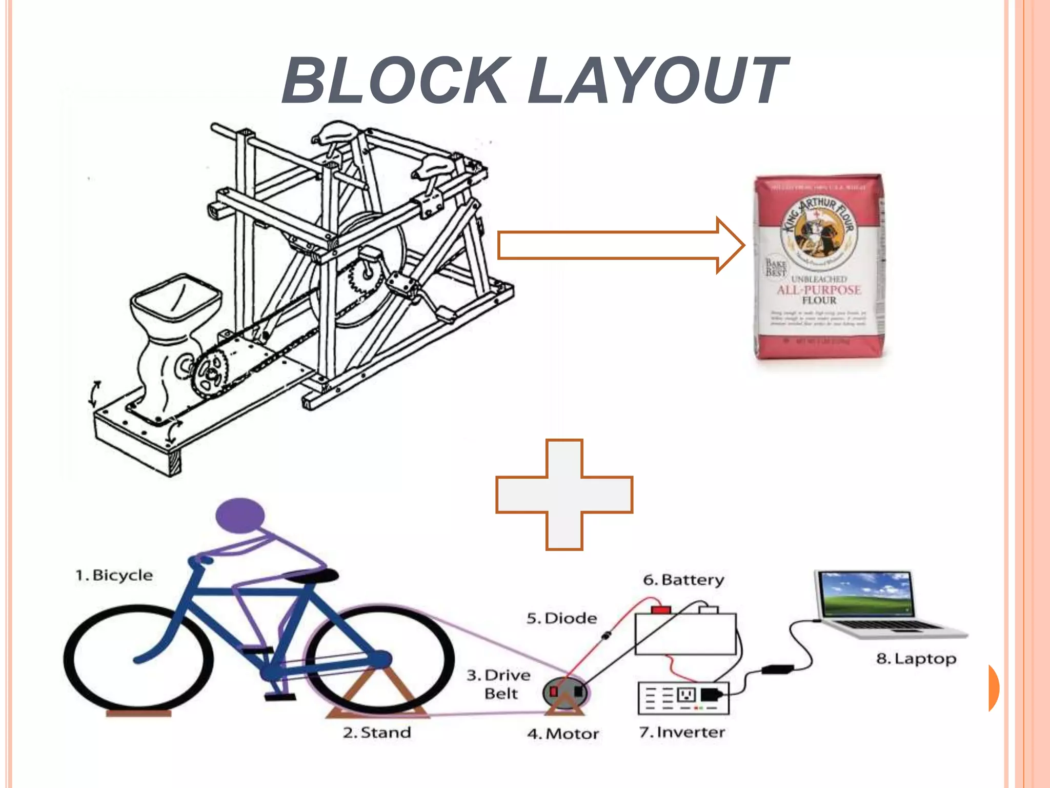
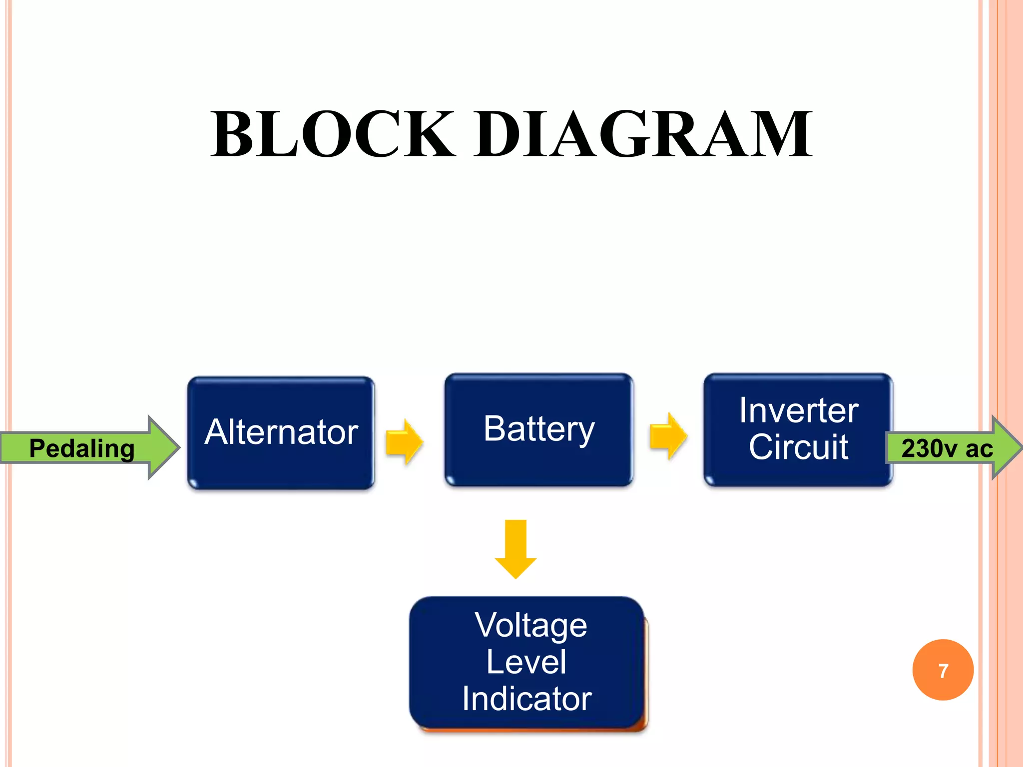
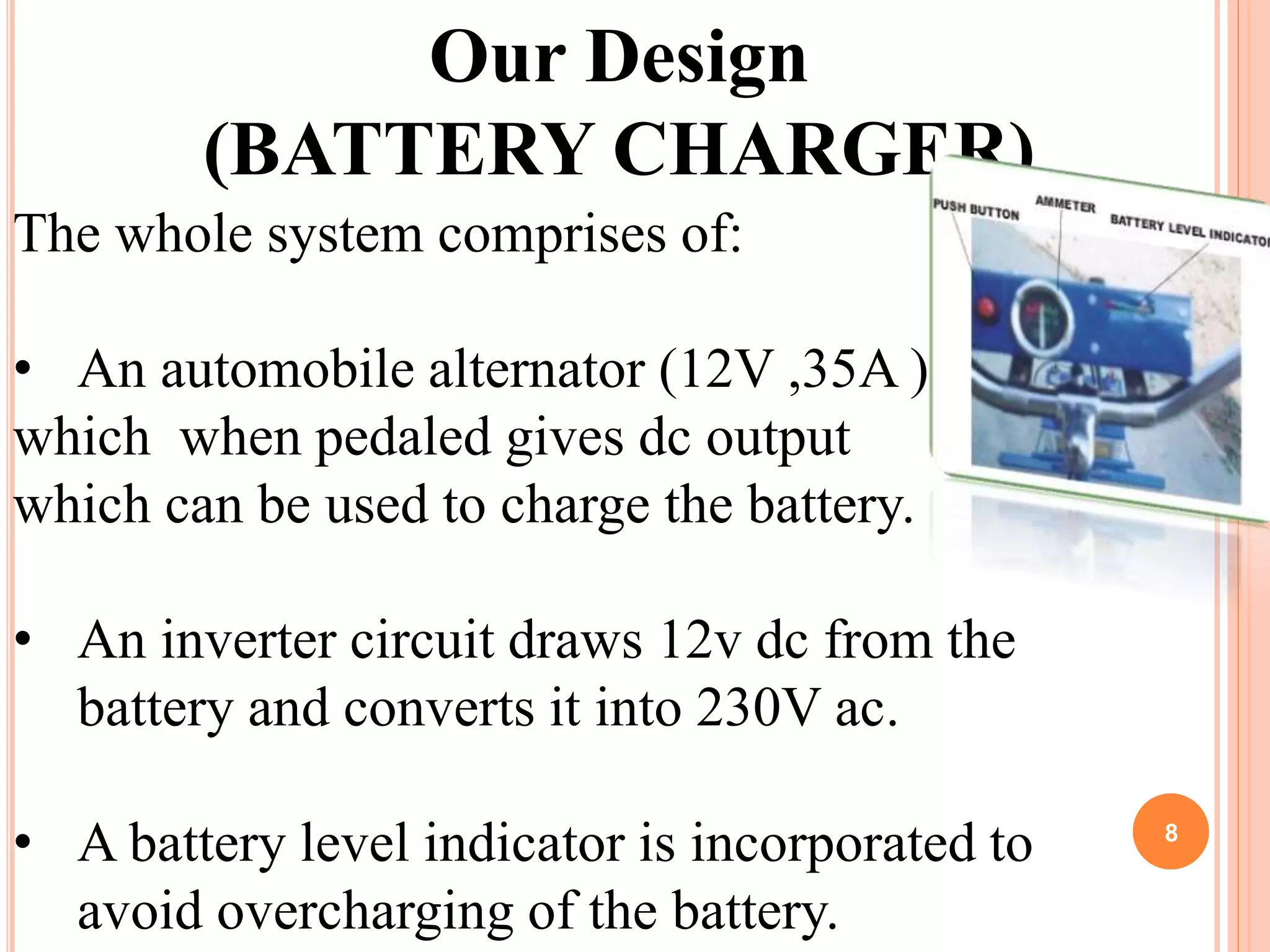
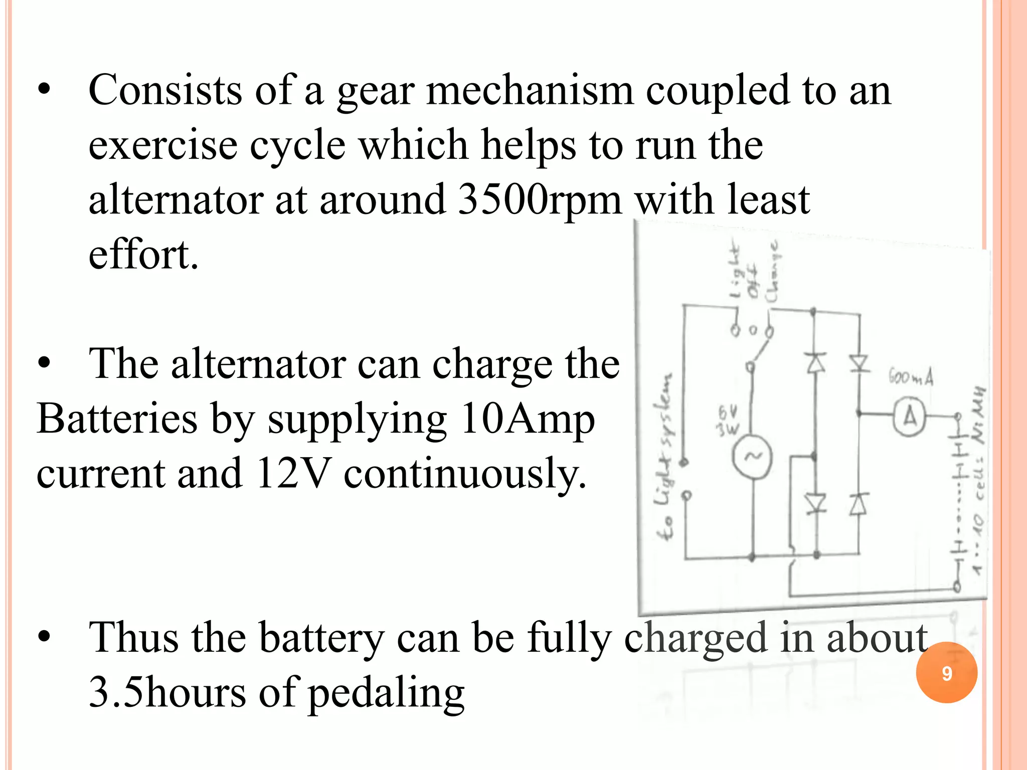
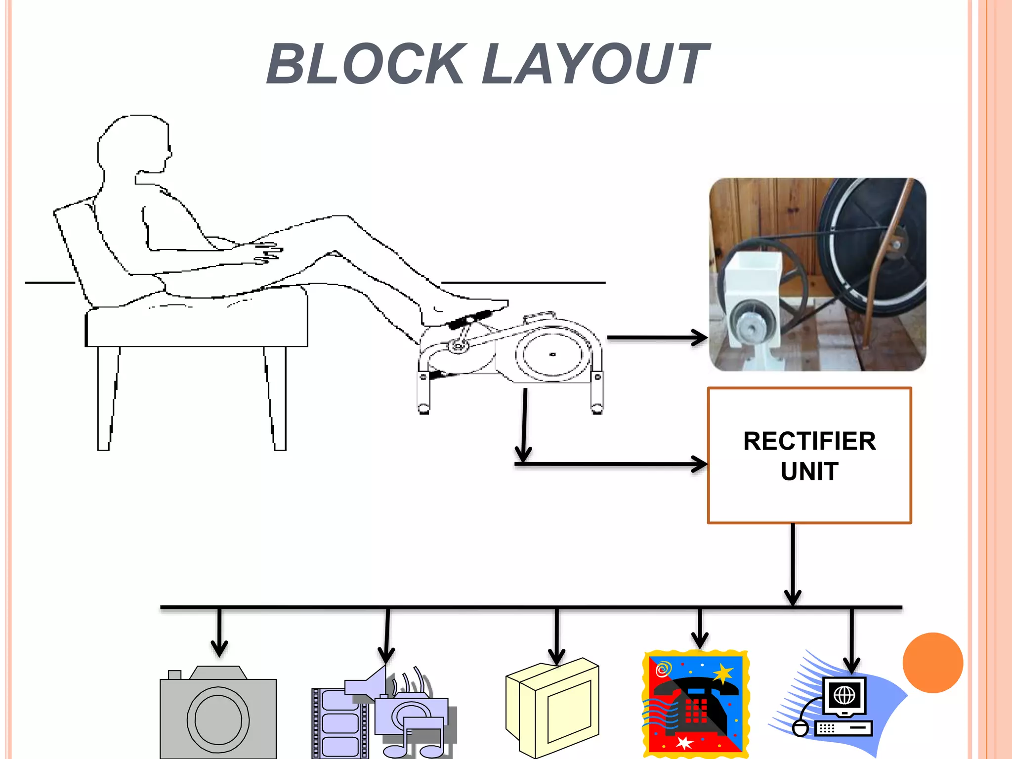
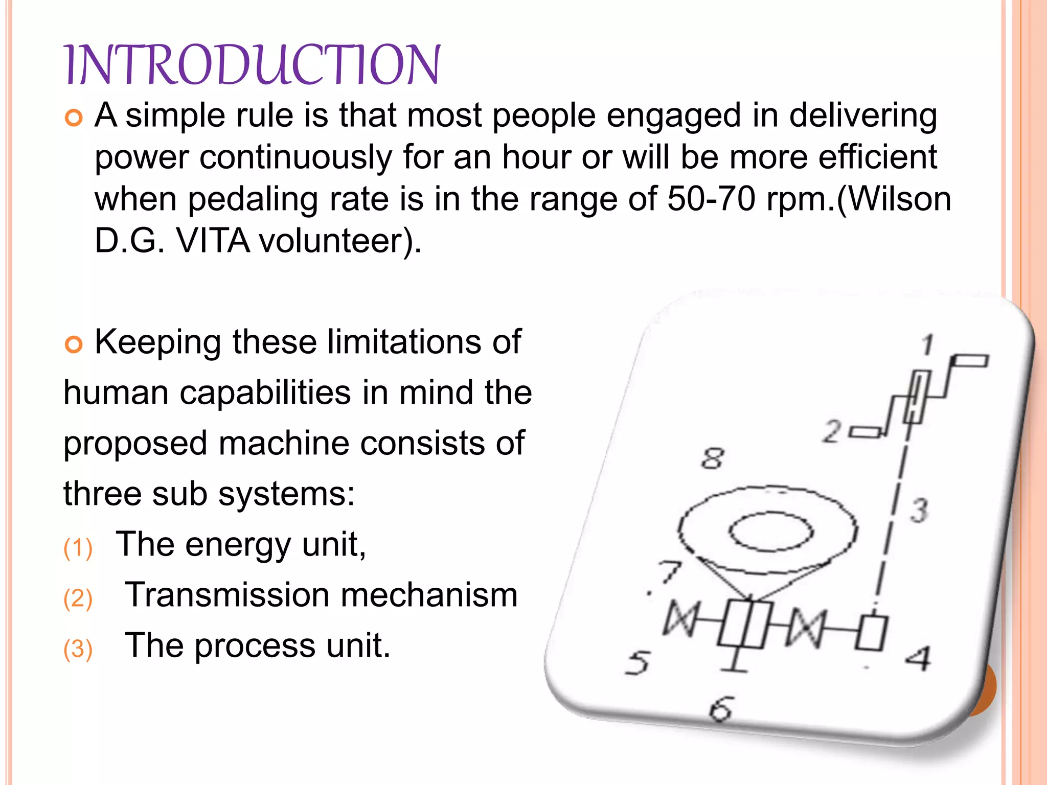
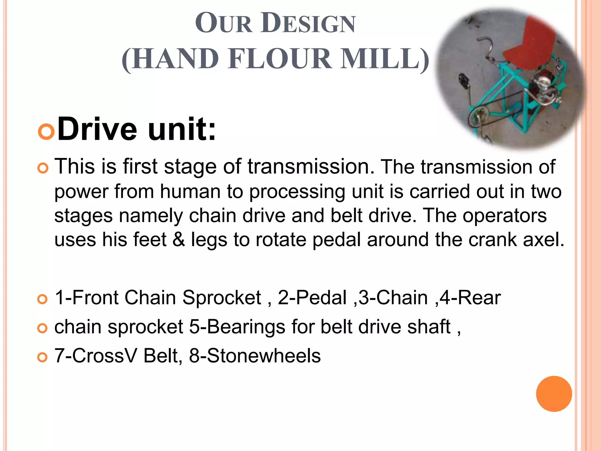
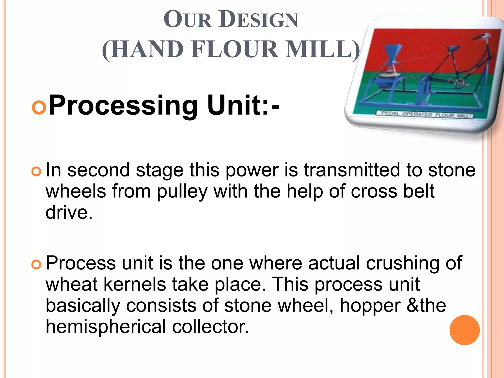
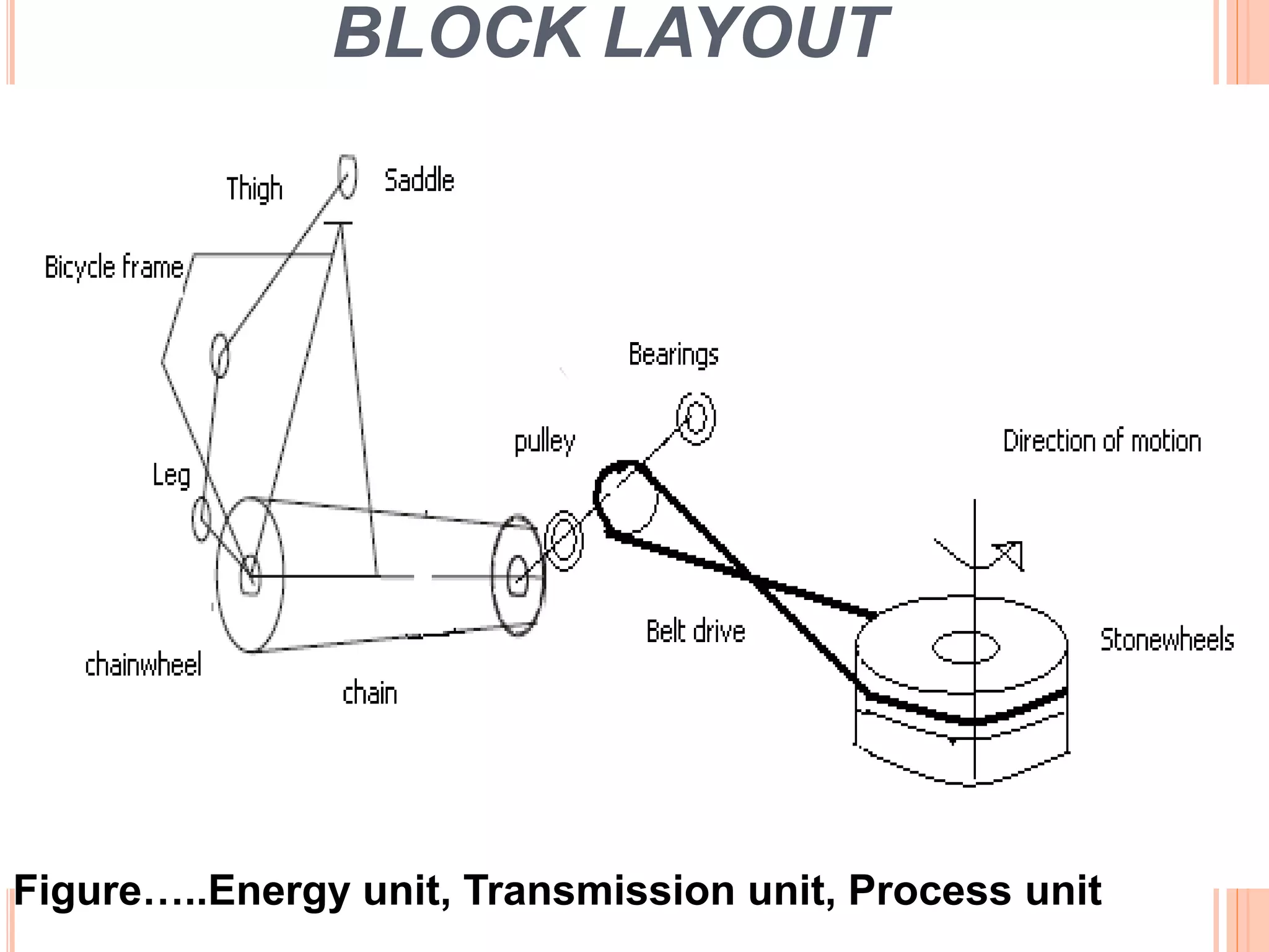
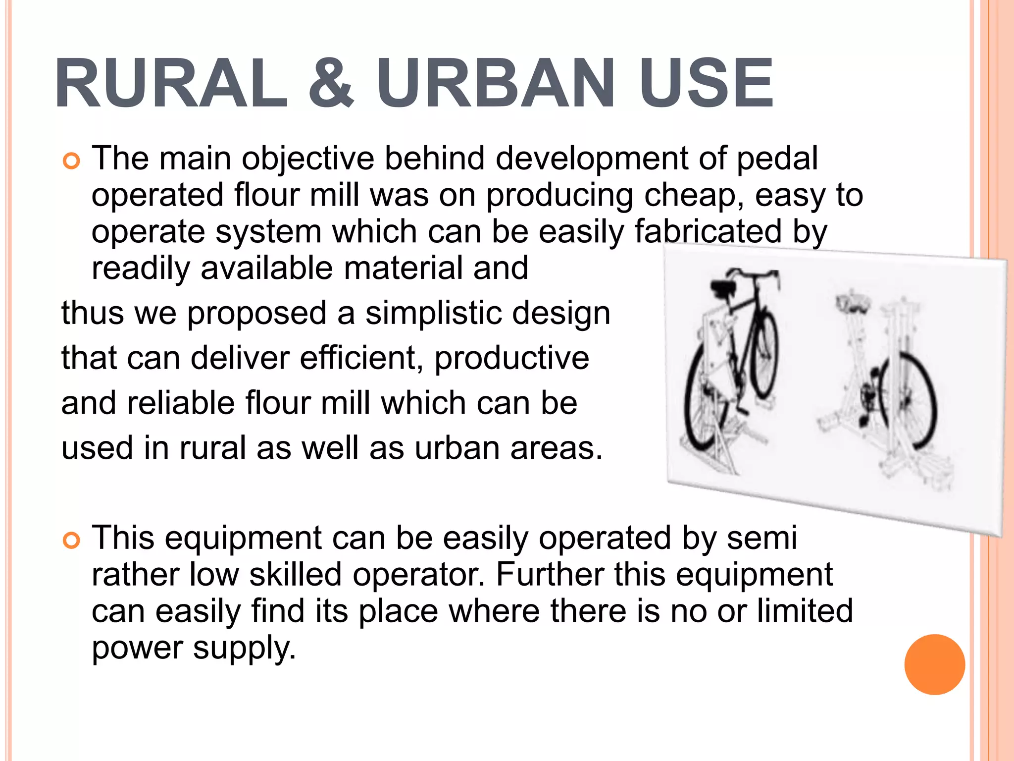
MADE BY :-------
PUSHPENDRA SINGH
2
AIM OF THE PROJECT
• Producing our own electricity by pedaling an
exercise cycle.
• Saves energy which is used for charging the
batteries in conventional inverter system.
• Reduction in electricity bill.
• stationary pedal powered flour mill
• Provides a method for physical exercise
besides serving its main purpose.
BLOCK LAYOUT
INTRODUCTION
 The present design relates to very compact and
easily portable power-generating unit,
 which besides being used as a power generator.
 The power-generating unit is pedal operated.
 As per the suitability of individual user the height of
the present design can be adjusted. The design
enables hands free operation and simultaneously the
user can engage himself in other activities like
reading, watching TV etc. The user can relax
intermittently without stopping the motion of the rotor
unit abruptly.
COMPONENTS
(POWER GENERATION)
 DC Motor
 (capable of producing enough V to charge battery)
 Rubber Belt
 (capable of being fixed to rotor)
 Old Bicycle Rim
 Nails
 Scrap Wood
 NiMH Battery (4.8 V, 150 mAh)
 Copper Wire
 Diode
 Resistor (120 Ohm)
 Lengths of wire
 Alligator clips
7
Alternator Battery
Inverter
CircuitPedaling 230v ac
BLOCK DIAGRAM
Voltage
Level
Indicator
8
Our Design
(BATTERY CHARGER)
The whole system comprises of:
• An automobile alternator (12V ,35A )
which when pedaled gives dc output
which can be used to charge the battery.
• An inverter circuit draws 12v dc from the
battery and converts it into 230V ac.
• A battery level indicator is incorporated to
avoid overcharging of the battery.
9
• Consists of a gear mechanism coupled to an
exercise cycle which helps to run the
alternator at around 3500rpm with least
effort.
• The alternator can charge the
Batteries by supplying 10Amp
current and 12V continuously.
• Thus the battery can be fully charged in about
3.5hours of pedaling
BLOCK LAYOUT
RECTIFIER
UNIT
WORKING CONCEPT
 The force applied to the pedals gets transmitted to the
rotor unit of power generating device (D.C MOTOR)
through chain-sprocket and gear train. The sizes of
sprockets and gears are so chosen to achieve suitable
rotating speed of the rotor for power generation.
 The shape and size of rotor is chosen to act as a flywheel
and impart suitable moment of inertia. The electrical power
so produced can be fed to a rectifier unit and plurality of
electrical connectors in the rectifier unit provides electrical
power to various electrical devices.
 A DC motor is generally used in applications that require
accurate speed control. The motor is connected to a power
supply which provides electrical current to the windings (coils) in
the rotor. When a current is passed through windings, a
magnetic field is produced. This magnetic field causes the rotor
to spin therefore creating useful mechanical work.
 These windings may also be used to
induce a voltage if the reverse action is
taken (rotor is manually spun and the
DC motor acts as a generator).
 This can be explained by Faraday’s Law of Induction which in
short states that a voltage is induced by a changing magnetic
field. The presence of the magnetic fields makes it possible to
produce an electric current and generate power.
RURAL USE
 For schools (especially boarding schools),
meetings, NGO and movement offices, there will be many
people who can easily share the pedaling at night. Put
each CFL in a different room or region and people can
take turns pedaling. The lights will be ON only when you
pedal.
 Put one 11 W CFL in each house and connect all of
them in parallel to the pedal generator. At night each
family or household can take 30 minutes or 45 minutes
turns pedaling, lighting all houses as they pedal. If 3
houses are sharing a generator then 3 x 45 Minutes = 2
Hours, 15 Minutes lights for everyone, say from 7-9:15
PM.
URBAN USE
 If the usage is solely as an exercise cycle and to
demonstrate the principle of alternate energy in
urban schools, then instead of the more expensive
CFLs you can connect in parallel a few (say 3-4),
12 V, 20-30 W bulbs (that you can get from any
auto shop for a few rupees each).
 The ammeter indicates the current you are
supplying or the rate at which calories are being
burnt. You can also connect some CFLs in parallel
with the auto bulbs if you wish.
4C: OTHER USES OF PEDAL
GENERATOR
 You can run any 12 V device such as mike system,
radio, tape recorder, laptop through 12 V adapter
and TV (of 12 V).
 If you want to run lower voltage
equipment (such as 6 V radio) then use
your hands to turn the pedals and do
not use the 12 V battery.
 To charge lower voltage batteries, use your hand
and turn the pedals slowly.
INTRODUCTION
 A simple rule is that most people engaged in delivering
power continuously for an hour or will be more efficient
when pedaling rate is in the range of 50-70 rpm.(Wilson
D.G. VITA volunteer).
 Keeping these limitations of
human capabilities in mind the
proposed machine consists of
three sub systems:
(1) The energy unit,
(2) Transmission mechanism
(3) The process unit.
INTRODUCTION
 The energy unit basically consists of conventional
bicycle mechanism; the transmission mechanism
consists of chain drive running over a pair of
sprockets and belt drive running over pulley and
stone wheels.
 The process unit is a pair of stone wheels mounted
over one another where the wheat gets crushed
into powered form to produce wheat flour. All these
units are assembled on bicycle like structure(seat,
saddle, handle etc).
COMPONENT
(FLOUR MILL)
 Bicycle chain -one and a half
 V-belting
 Cardboard
 Mortar (16kgs sand and 8kgs cement)
 Rim tape (rubber strip or tape)
 Cotter pins (6)
 The Chain Assembles
 Flywheel
 Chassis OF STEEL
Hand Mill
OUR DESIGN
(HAND FLOUR MILL)
Drive unit:
 This is first stage of transmission. The transmission of
power from human to processing unit is carried out in two
stages namely chain drive and belt drive. The operators
uses his feet & legs to rotate pedal around the crank axel.
 1-Front Chain Sprocket , 2-Pedal ,3-Chain ,4-Rear
 chain sprocket 5-Bearings for belt drive shaft ,
 7-CrossV Belt, 8-Stonewheels
OUR DESIGN
(HAND FLOUR MILL)
Processing Unit:-
 In second stage this power is transmitted to stone
wheels from pulley with the help of cross belt
drive.
 Process unit is the one where actual crushing of
wheat kernels take place. This process unit
basically consists of stone wheel, hopper &the
hemispherical collector.
BLOCK LAYOUT
Figure…..Energy unit, Transmission unit, Process unit
WORKING CONCEPT
 In conventional stone wheel mechanism
the intermittent flow is required to get fine
output. The same type of arrangements of
flow is made in Pedal operated flour mill.
 It consists of Hopper mechanism in which the grains are
stored. It is having a flow control unit, which is connected by
means of mechanical spring to the left hand brakes.
 By breaking, the flow may control. The output of the stone
wheel mechanism is collected between a hemispherical
collector which is located below the stone wheel mechanism.
RURAL & URBAN USE
 The main objective behind development of pedal
operated flour mill was on producing cheap, easy to
operate system which can be easily fabricated by
readily available material and
thus we proposed a simplistic design
that can deliver efficient, productive
and reliable flour mill which can be
used in rural as well as urban areas.
 This equipment can be easily operated by semi
rather low skilled operator. Further this equipment
can easily find its place where there is no or limited
power supply.
25
ATTRACTIONS OF OUR PROJECT
• Can be used in rural areas where electricity is out of
reach
• Any time charging, even during power failure
• Power Saving
• Reduces electricity bill
• Modified versions can be used for running house hold
applications like television and other appliances.
• Low cost
• Simple in construction
• Easily operated HAND FLOUR-MILL.
26
CONCLUSION
The above proposed project named “THE PEDAL POWERED
GENERATION ” & “THE PEDAL POWERED FLOUR
MILL” has been designed and materialized on the objective of
providing an alternative source of electricity as well as an
effective mode of FLOUR MILLING. We believe that this
project, if effectively used may be considered as an innovative
and a good solution for the energy crisis as far as a developing
nation like India is concerned.
Presentation2

Presentation2

  • 1.
  • 2.
    2 AIM OF THEPROJECT • Producing our own electricity by pedaling an exercise cycle. • Saves energy which is used for charging the batteries in conventional inverter system. • Reduction in electricity bill. • stationary pedal powered flour mill • Provides a method for physical exercise besides serving its main purpose.
  • 3.
  • 5.
    INTRODUCTION  The presentdesign relates to very compact and easily portable power-generating unit,  which besides being used as a power generator.  The power-generating unit is pedal operated.  As per the suitability of individual user the height of the present design can be adjusted. The design enables hands free operation and simultaneously the user can engage himself in other activities like reading, watching TV etc. The user can relax intermittently without stopping the motion of the rotor unit abruptly.
  • 6.
    COMPONENTS (POWER GENERATION)  DCMotor  (capable of producing enough V to charge battery)  Rubber Belt  (capable of being fixed to rotor)  Old Bicycle Rim  Nails  Scrap Wood  NiMH Battery (4.8 V, 150 mAh)  Copper Wire  Diode  Resistor (120 Ohm)  Lengths of wire  Alligator clips
  • 7.
    7 Alternator Battery Inverter CircuitPedaling 230vac BLOCK DIAGRAM Voltage Level Indicator
  • 8.
    8 Our Design (BATTERY CHARGER) Thewhole system comprises of: • An automobile alternator (12V ,35A ) which when pedaled gives dc output which can be used to charge the battery. • An inverter circuit draws 12v dc from the battery and converts it into 230V ac. • A battery level indicator is incorporated to avoid overcharging of the battery.
  • 9.
    9 • Consists ofa gear mechanism coupled to an exercise cycle which helps to run the alternator at around 3500rpm with least effort. • The alternator can charge the Batteries by supplying 10Amp current and 12V continuously. • Thus the battery can be fully charged in about 3.5hours of pedaling
  • 10.
  • 11.
    WORKING CONCEPT  Theforce applied to the pedals gets transmitted to the rotor unit of power generating device (D.C MOTOR) through chain-sprocket and gear train. The sizes of sprockets and gears are so chosen to achieve suitable rotating speed of the rotor for power generation.  The shape and size of rotor is chosen to act as a flywheel and impart suitable moment of inertia. The electrical power so produced can be fed to a rectifier unit and plurality of electrical connectors in the rectifier unit provides electrical power to various electrical devices.
  • 12.
     A DCmotor is generally used in applications that require accurate speed control. The motor is connected to a power supply which provides electrical current to the windings (coils) in the rotor. When a current is passed through windings, a magnetic field is produced. This magnetic field causes the rotor to spin therefore creating useful mechanical work.  These windings may also be used to induce a voltage if the reverse action is taken (rotor is manually spun and the DC motor acts as a generator).  This can be explained by Faraday’s Law of Induction which in short states that a voltage is induced by a changing magnetic field. The presence of the magnetic fields makes it possible to produce an electric current and generate power.
  • 13.
    RURAL USE  Forschools (especially boarding schools), meetings, NGO and movement offices, there will be many people who can easily share the pedaling at night. Put each CFL in a different room or region and people can take turns pedaling. The lights will be ON only when you pedal.  Put one 11 W CFL in each house and connect all of them in parallel to the pedal generator. At night each family or household can take 30 minutes or 45 minutes turns pedaling, lighting all houses as they pedal. If 3 houses are sharing a generator then 3 x 45 Minutes = 2 Hours, 15 Minutes lights for everyone, say from 7-9:15 PM.
  • 14.
    URBAN USE  Ifthe usage is solely as an exercise cycle and to demonstrate the principle of alternate energy in urban schools, then instead of the more expensive CFLs you can connect in parallel a few (say 3-4), 12 V, 20-30 W bulbs (that you can get from any auto shop for a few rupees each).  The ammeter indicates the current you are supplying or the rate at which calories are being burnt. You can also connect some CFLs in parallel with the auto bulbs if you wish.
  • 15.
    4C: OTHER USESOF PEDAL GENERATOR  You can run any 12 V device such as mike system, radio, tape recorder, laptop through 12 V adapter and TV (of 12 V).  If you want to run lower voltage equipment (such as 6 V radio) then use your hands to turn the pedals and do not use the 12 V battery.  To charge lower voltage batteries, use your hand and turn the pedals slowly.
  • 17.
    INTRODUCTION  A simplerule is that most people engaged in delivering power continuously for an hour or will be more efficient when pedaling rate is in the range of 50-70 rpm.(Wilson D.G. VITA volunteer).  Keeping these limitations of human capabilities in mind the proposed machine consists of three sub systems: (1) The energy unit, (2) Transmission mechanism (3) The process unit.
  • 18.
    INTRODUCTION  The energyunit basically consists of conventional bicycle mechanism; the transmission mechanism consists of chain drive running over a pair of sprockets and belt drive running over pulley and stone wheels.  The process unit is a pair of stone wheels mounted over one another where the wheat gets crushed into powered form to produce wheat flour. All these units are assembled on bicycle like structure(seat, saddle, handle etc).
  • 19.
    COMPONENT (FLOUR MILL)  Bicyclechain -one and a half  V-belting  Cardboard  Mortar (16kgs sand and 8kgs cement)  Rim tape (rubber strip or tape)  Cotter pins (6)  The Chain Assembles  Flywheel  Chassis OF STEEL Hand Mill
  • 20.
    OUR DESIGN (HAND FLOURMILL) Drive unit:  This is first stage of transmission. The transmission of power from human to processing unit is carried out in two stages namely chain drive and belt drive. The operators uses his feet & legs to rotate pedal around the crank axel.  1-Front Chain Sprocket , 2-Pedal ,3-Chain ,4-Rear  chain sprocket 5-Bearings for belt drive shaft ,  7-CrossV Belt, 8-Stonewheels
  • 21.
    OUR DESIGN (HAND FLOURMILL) Processing Unit:-  In second stage this power is transmitted to stone wheels from pulley with the help of cross belt drive.  Process unit is the one where actual crushing of wheat kernels take place. This process unit basically consists of stone wheel, hopper &the hemispherical collector.
  • 22.
    BLOCK LAYOUT Figure…..Energy unit,Transmission unit, Process unit
  • 23.
    WORKING CONCEPT  Inconventional stone wheel mechanism the intermittent flow is required to get fine output. The same type of arrangements of flow is made in Pedal operated flour mill.  It consists of Hopper mechanism in which the grains are stored. It is having a flow control unit, which is connected by means of mechanical spring to the left hand brakes.  By breaking, the flow may control. The output of the stone wheel mechanism is collected between a hemispherical collector which is located below the stone wheel mechanism.
  • 24.
    RURAL & URBANUSE  The main objective behind development of pedal operated flour mill was on producing cheap, easy to operate system which can be easily fabricated by readily available material and thus we proposed a simplistic design that can deliver efficient, productive and reliable flour mill which can be used in rural as well as urban areas.  This equipment can be easily operated by semi rather low skilled operator. Further this equipment can easily find its place where there is no or limited power supply.
  • 25.
    25 ATTRACTIONS OF OURPROJECT • Can be used in rural areas where electricity is out of reach • Any time charging, even during power failure • Power Saving • Reduces electricity bill • Modified versions can be used for running house hold applications like television and other appliances. • Low cost • Simple in construction • Easily operated HAND FLOUR-MILL.
  • 26.
    26 CONCLUSION The above proposedproject named “THE PEDAL POWERED GENERATION ” & “THE PEDAL POWERED FLOUR MILL” has been designed and materialized on the objective of providing an alternative source of electricity as well as an effective mode of FLOUR MILLING. We believe that this project, if effectively used may be considered as an innovative and a good solution for the energy crisis as far as a developing nation like India is concerned.