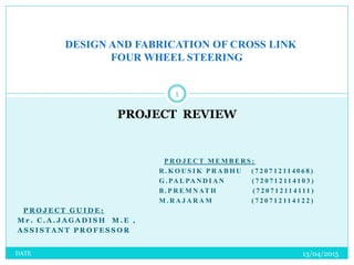
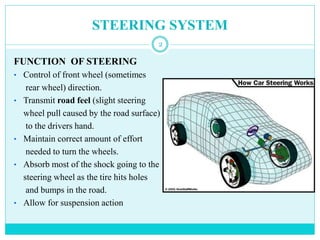
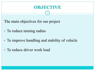
This document summarizes a project to design and fabricate a cross link four wheel steering system. The project aims to reduce turning radius, improve vehicle handling and stability, and reduce driver workload. It discusses the existing front wheel steering system and limitations. The four wheel steering system is described as connecting all four wheels to improve steering response at high speeds and decrease turning radius at low speeds. Design calculations and comparisons to a two wheel steering system are provided. Potential applications and advantages of the four wheel steering system are outlined.
![CROSS LINK MECHANISM
8
The material selected for cross bar
and side bar is duplex 2205 stainless
steel hollow pipes of 25.4mm
diameter and 2mm thickness due to
its high tensile strength and its
fracture toughness.
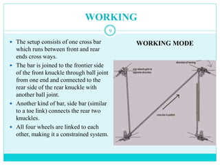
The setup requires the use of three
ball joints along with a steering rack
and pinion assembly and a modified
knuckle for the attachment of shaft in
the rear end diagonally.
The material selected for the bar is a
type of super stainless steel having
following properties [2]:
Ultimate strength = 620 MPa Yield
Strength = 570 MPa Density = 7805
Kg/m3
NOMAL MODE](https://image.slidesharecdn.com/final-151016152601-lva1-app6891-151125070148-lva1-app6892/85/Final-151016152601-lva1-app6891-8-320.jpg)
![REFERENCE
[1] PACEJKA, H. B. 2006. Tyre Mechanics and Vehicle Dynamics,
Butterworth-Heinemann .
[2] Bansal, R.K. 2010. A textbook of Strength of Materials, Laxmi
Publications.
[3] REIMPELL, J. 2001. The Automotive Chassis - Engineering
Principles, Butterworth-Heinemann .
[4] William F. Milliken, Douglas L. Milliken, 1995. Race Car Vehicle
Dynamics , Society of Automotive Engineers
[5] Swanson Analysis Systems, Inc. ANSYS software (Version 14.0).
[6] Dassault Systèmes SolidWorks Corp., a subsidiary of Dassault
Systèmes, S. A. (Vélizy, France) Solidworks software
(December9,2009), version 4.
18](https://image.slidesharecdn.com/final-151016152601-lva1-app6891-151125070148-lva1-app6892/85/Final-151016152601-lva1-app6891-18-320.jpg)