Downloaded 74 times
![Solid Earth Geophysics Ali Oncel [email_address] Department of Earth Sciences KFUPM Today’s class: Seismology Measuring the Interior Reading: Fowler Chapter 4](https://image.slidesharecdn.com/lecture17-091219233233-phpapp01/85/ONCEL-AKADEMI-SOLID-EARTH-GEOPHYSICS-1-320.jpg)
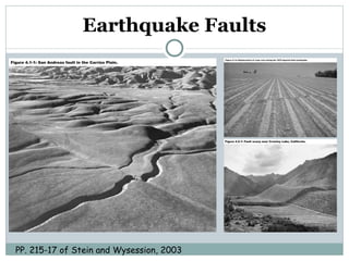
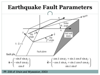
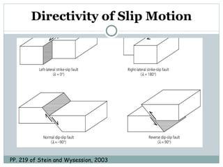
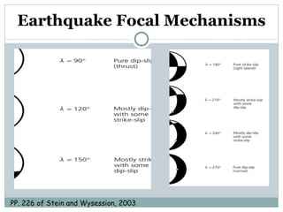
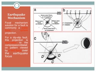

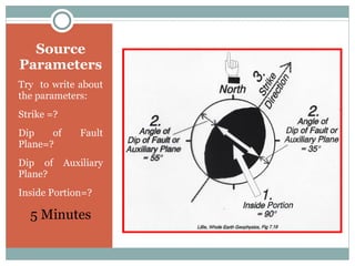
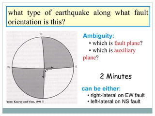
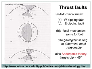
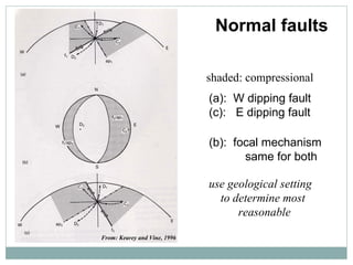
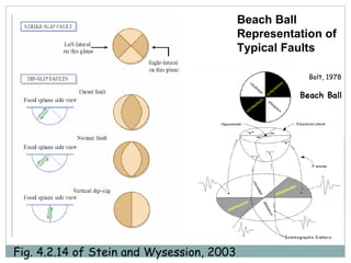
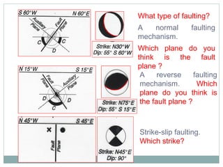
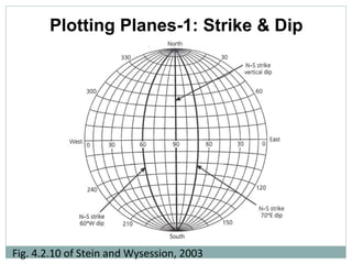
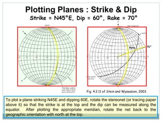
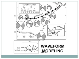
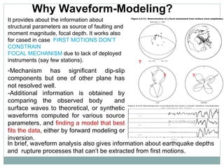
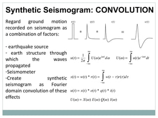

This document provides an overview of topics in seismology, including measuring earthquake faults, fault parameters, focal mechanisms, and waveform modeling. It discusses different types of faults like normal faults, reverse faults, and strike-slip faults. It also covers plotting fault planes based on strike and dip, determining fault types from beach ball representations, and using waveform modeling to better resolve earthquake source parameters and focal mechanisms when first motion data is insufficient.