Downloaded 264 times

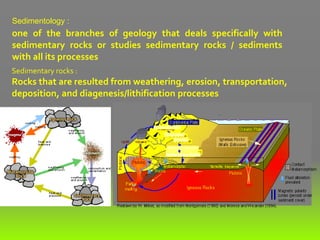
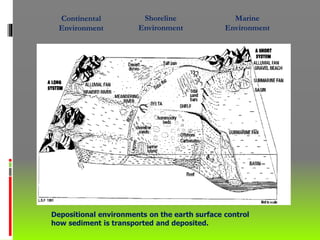

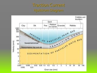
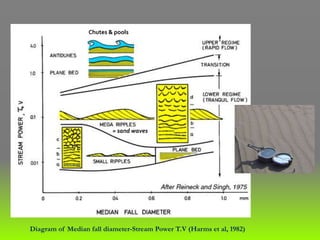
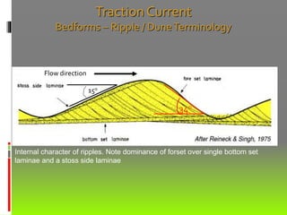
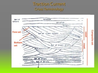


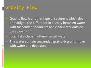
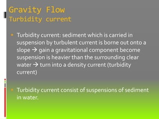
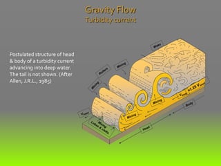
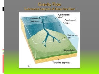
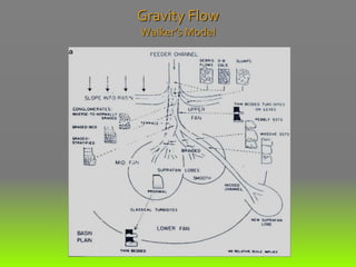
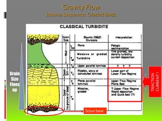

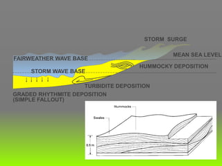

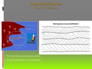
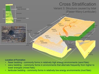
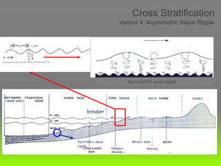

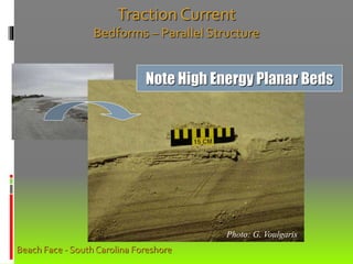
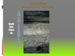

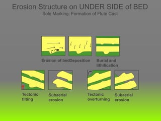
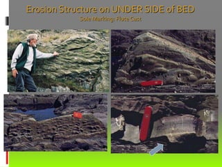


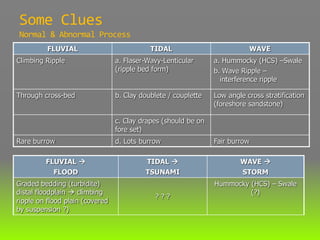
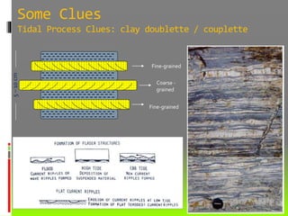
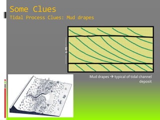
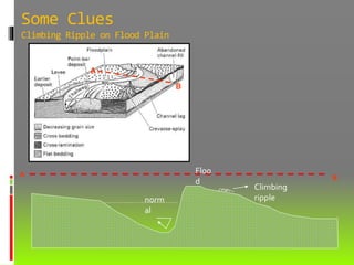

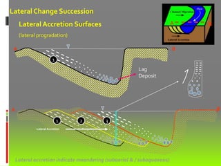


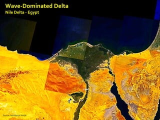
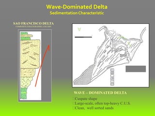
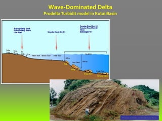

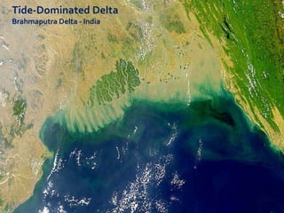


This document provides an overview of sedimentology and its applications in the petroleum industry. It discusses key concepts in sedimentology including sedimentary rocks, depositional environments, sediment transport processes, and sedimentary structures. These concepts are important for understanding reservoir heterogeneity, predicting texture, and informing exploration and production strategies. The document cautions against oversimplifying depositional environments and stresses the importance of analyzing sediment transport and depositional processes to avoid misinterpretation.


![Polymer [ बहुलक ] Chemistry Notes PDF - Irfanullah Mehar - JJ Sir Chemistry.pdf](https://cdn.slidesharecdn.com/ss_thumbnails/polymerchemistrynotespdf-irfanullahmehar-jjsirchemistry-260210172118-3f9b37f7-thumbnail.jpg?width=640&height=640&fit=bounds)


