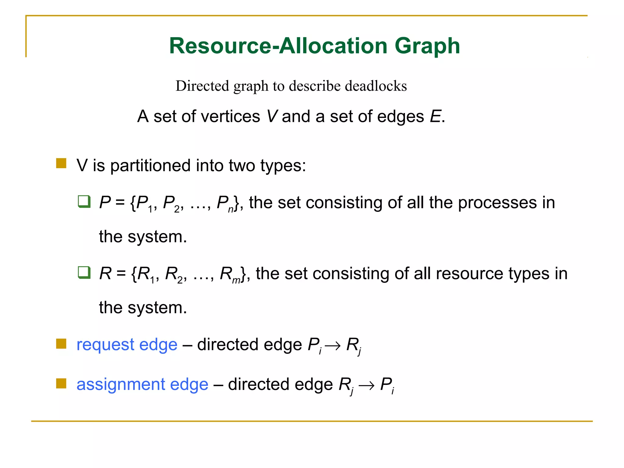
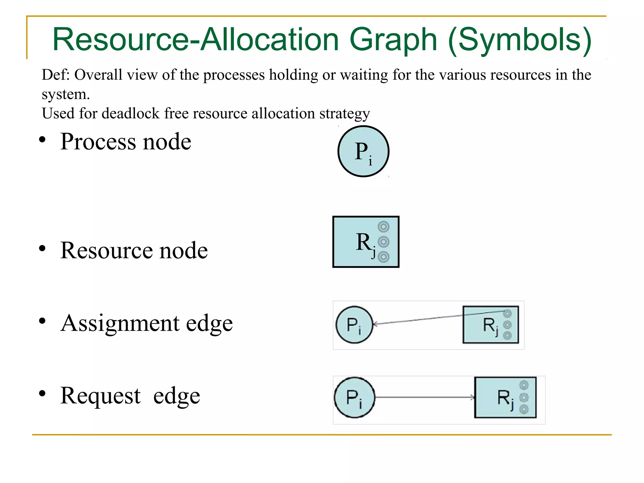
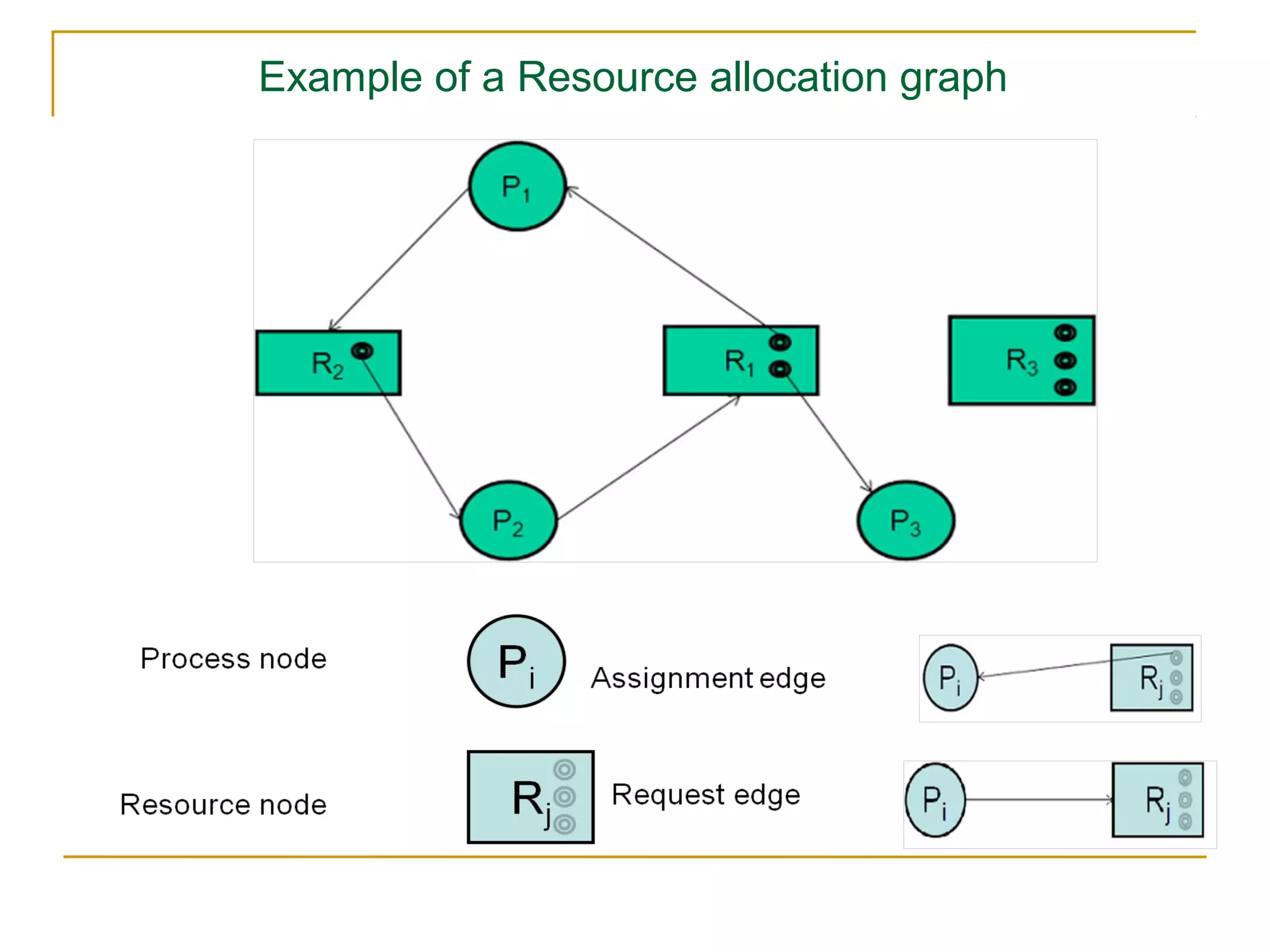
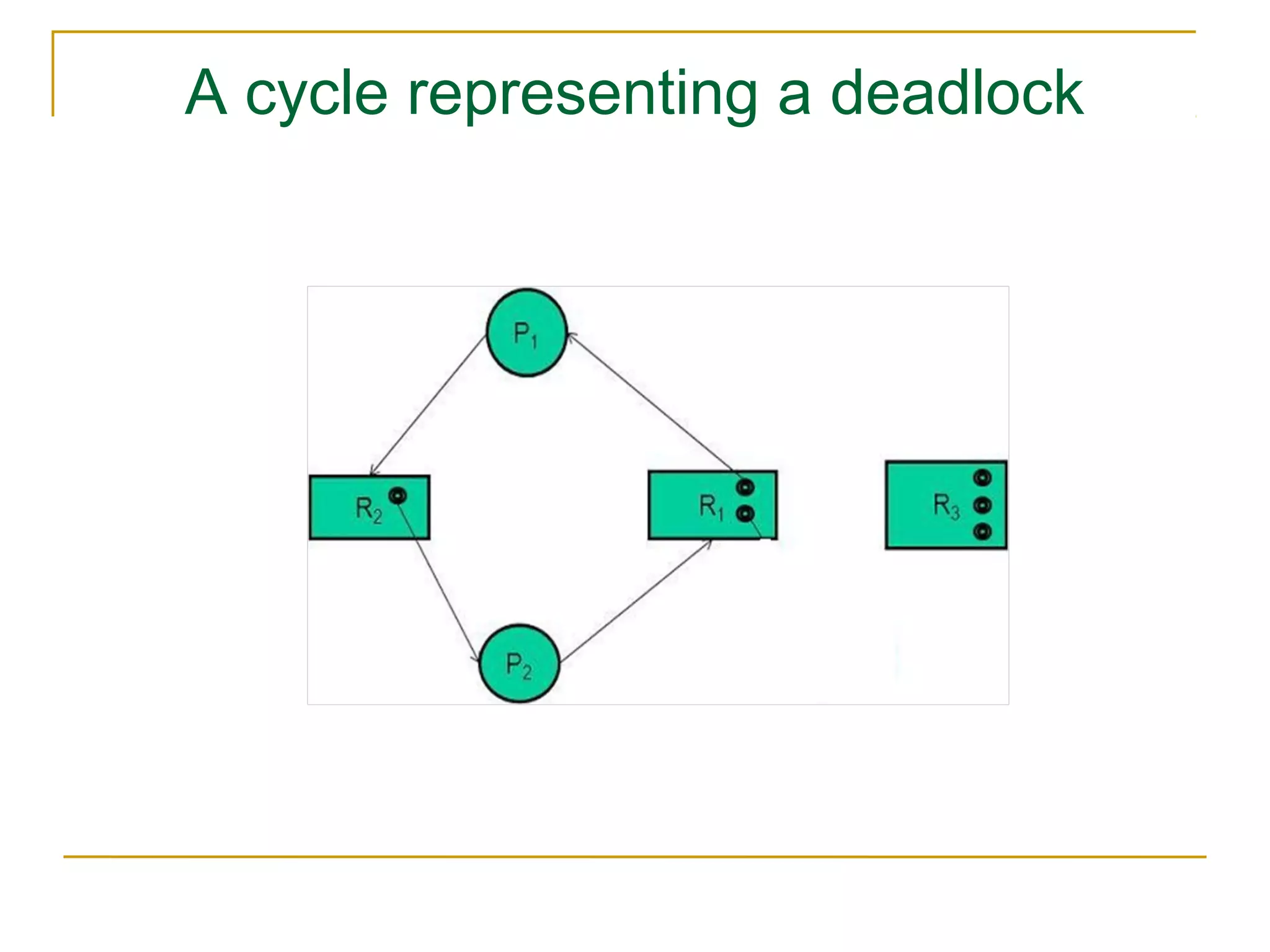
Downloaded 148 times


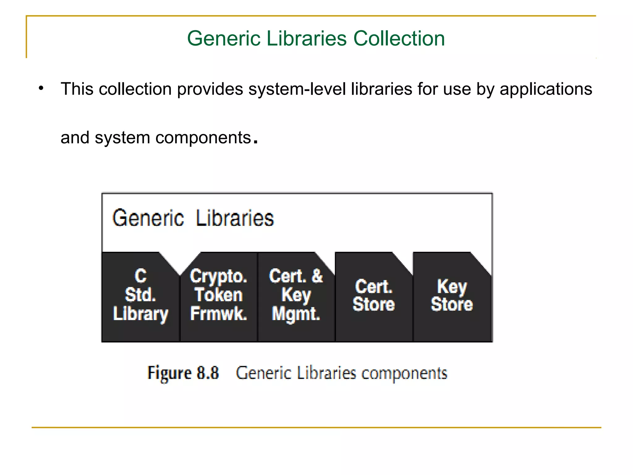
![Data Structures for the Banker’s Algorithm
Let n = number of processes, and m = number of resources types
Available: Vector of length m. If available [j] = k, there are k
instances of resource type Rj available
Max: n x m matrix. If Max [i,j] = k, then process Pi may request at
most k instances of resource type Rj
Allocation: n x m matrix. If Allocation[i,j] = k then Pi is currently
allocated k instances of Rj
Need: n x m matrix. If Need[i,j] = k, then Pi may need k more
instances of Rj to complete its task.
Need [i, j] = Max[i, j] – Allocation [i, j]](https://image.slidesharecdn.com/ch3mod-120927100457-phpapp02/75/scheduling-111-2048.jpg)
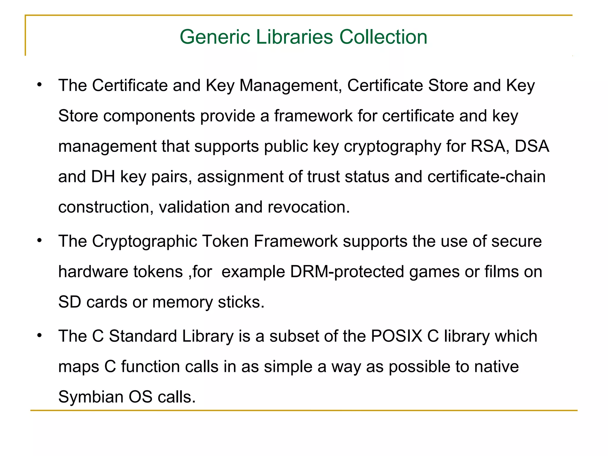
![Safety Algorithm
1. Let Work and Finish be vectors of length m and n, respectively.
Initialize:
Work = Available
Finish [i] = false for i = 0, 1, …, n- 1
2. Find an i such that both:
Requires m * n2 operation to
(a) Finish [i] = false
decide whether a state is safe.
(b) Needi ≤ Work
If no such i exists, go to step 4
3. Work = Work + Allocationi
Finish[i] = true
go to step 2
4. If Finish [i] == true for all i, then the system is in a safe state](https://image.slidesharecdn.com/ch3mod-120927100457-phpapp02/75/scheduling-112-2048.jpg)
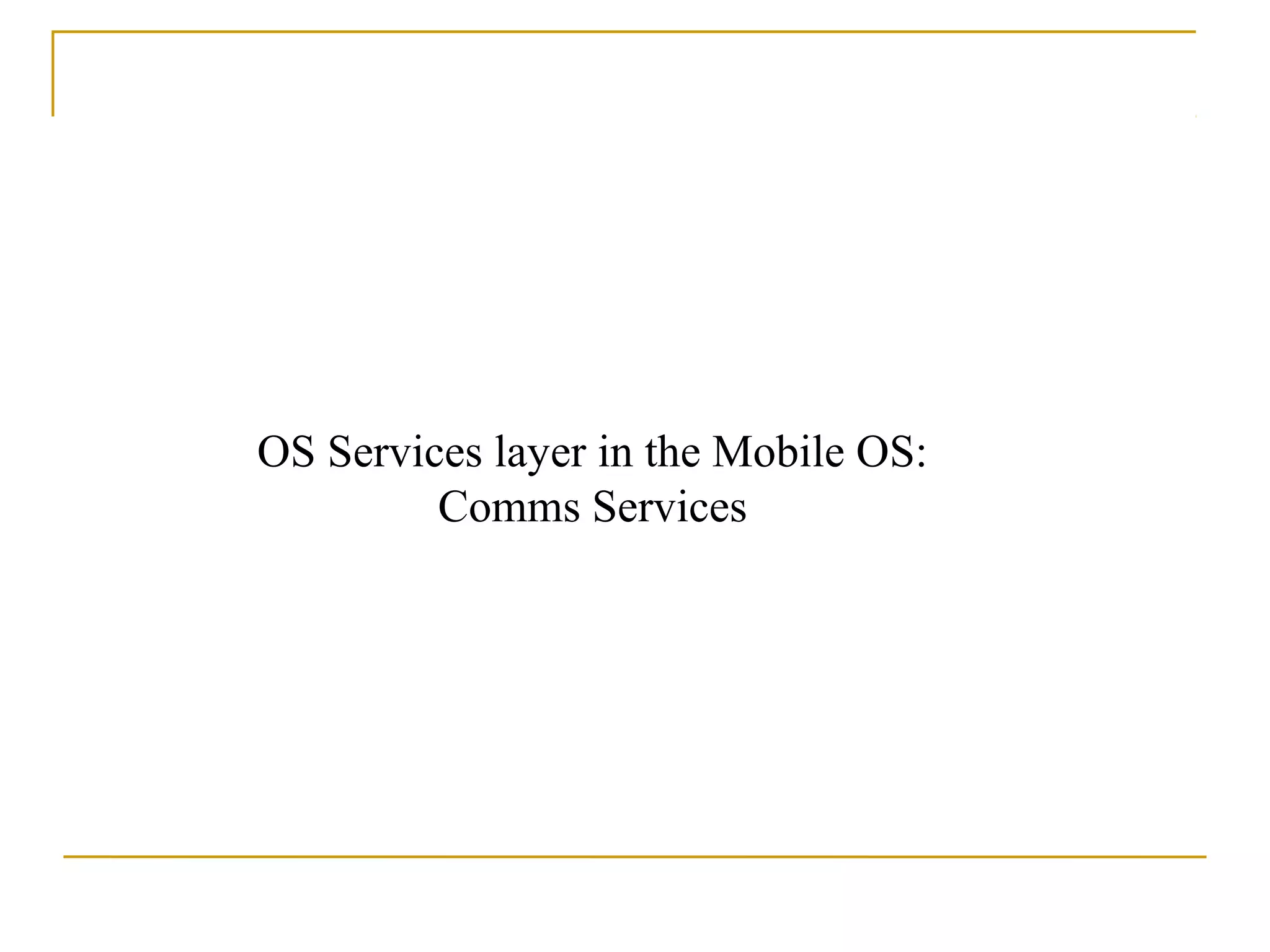
![Resource-Request Algorithm
Requesti = request vector for process Pi.
If Requesti [j] = k then process Pi wants k instances of resource
type Rj
1. If Requesti ≤ Needi go to step 2. Otherwise, raise error
condition, since process has exceeded its maximum claim
2. If Requesti ≤ Available, go to step 3. Otherwise Pi must wait,
since resources are not available
3. Pretend the system to allocate requested resources to Pi by
modifying the state as follows:
Available = Available – Requesti
Allocationi = Allocationi + Requesti
Needi = Needi – Requesti
If safe ⇒ the resources are allocated to Pi
If unsafe ⇒ Pi must wait, and the old resource-allocation
state is restored](https://image.slidesharecdn.com/ch3mod-120927100457-phpapp02/75/scheduling-113-2048.jpg)
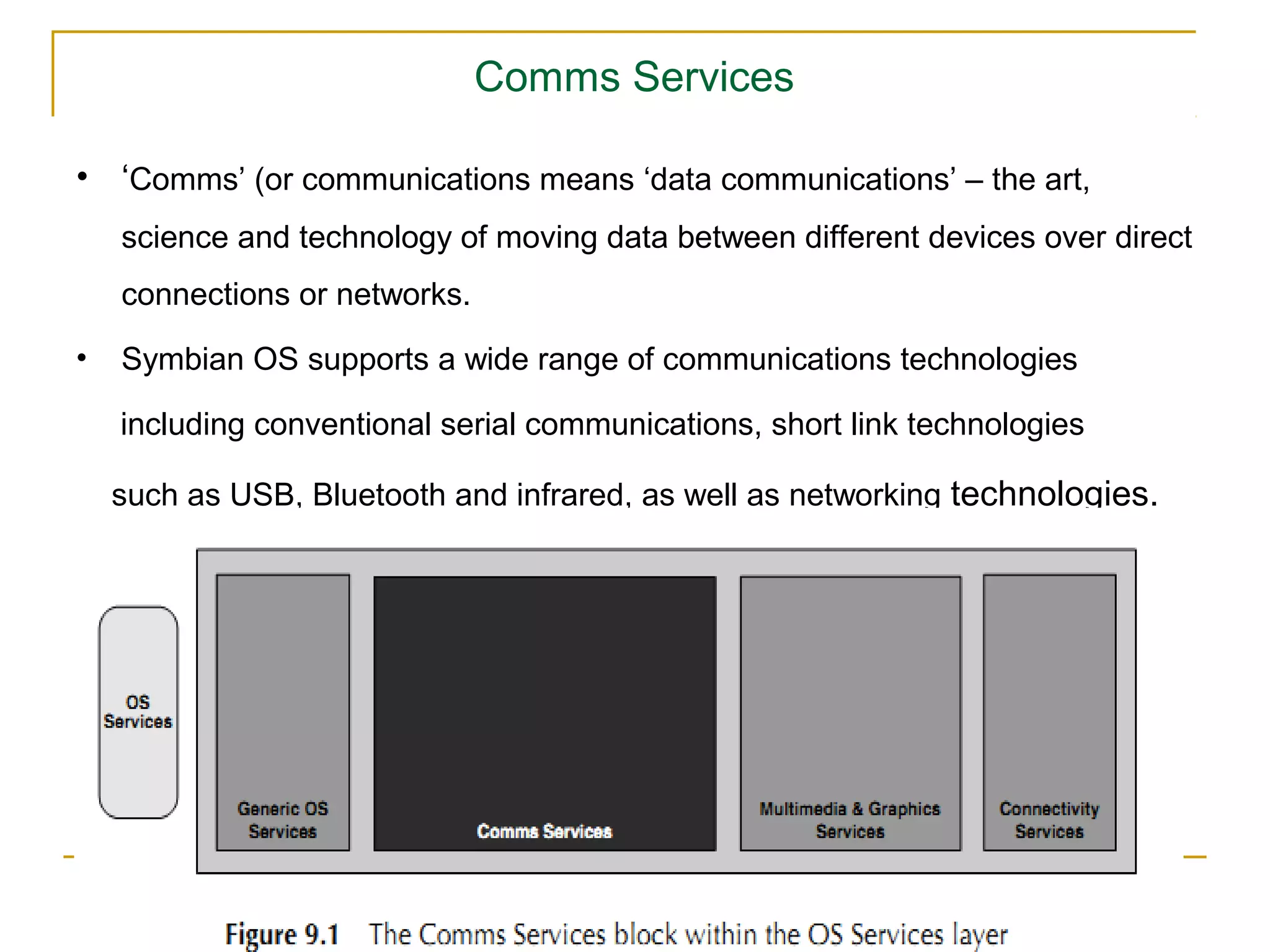
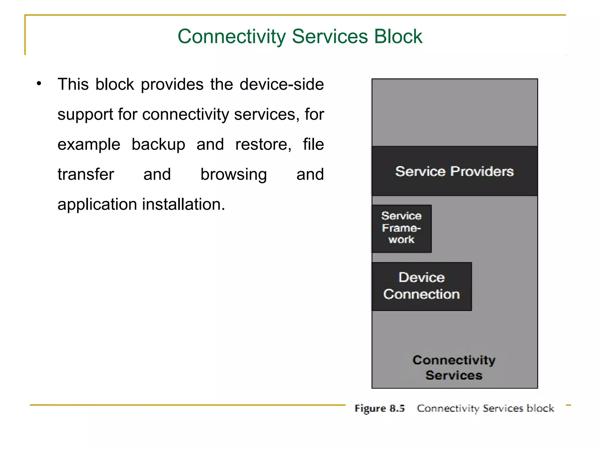
![Several Instances of a Resource Type
Available: A vector of length m indicates the number of available
resources of each type.
Allocation: An n x m matrix defines the number of resources of
each type currently allocated to each process.
Request: An n x m matrix indicates the current request of each
process. If Request [i,j ] = k, then process Pi is requesting k more
instances of resource type Rj.](https://image.slidesharecdn.com/ch3mod-120927100457-phpapp02/75/scheduling-122-2048.jpg)
![Detection Algorithm
1. Let Work and Finish be vectors of length m and n, respectively
Initialize:
(a) Work = Available
(b) For i = 1,2, …, n, if Allocationi ≠ 0, then
Finish[i] = false; otherwise, Finish[i] = true
2. Find an index i such that both:
(a) Finish[i] == false
(b) Requesti ≤ Work
If no such i exists, go to step 4](https://image.slidesharecdn.com/ch3mod-120927100457-phpapp02/75/scheduling-123-2048.jpg)
![Detection Algorithm (Cont.)
1. 3. Work = Work + Allocationi
Finish[i] = true
go to step 2
2. 4. If Finish[i] == false, for some i, 1 ≤ i ≤ n, then the system is in
deadlock state.
Moreover, if Finish[i] == false, then Pi is deadlocked
Algorithm requires an order of O(m x n2) operations to detect whether
the system is in deadlocked state](https://image.slidesharecdn.com/ch3mod-120927100457-phpapp02/75/scheduling-124-2048.jpg)
![Example of Detection Algorithm
Five processes P0 through P4; three resource types
A (7 instances), B (2 instances), and C (6 instances)
Snapshot at time T0:
Allocation Request Available
ABC ABC ABC
P0 010 000 000 (0 1 0 )
P1 200 202 ( 7 2 6)
P2 303 000 ( 3 1 3)
P3 211 100 (524)
P4 002 002 ( 5 2 6)
Sequence <P0, P2, P3, P1, P4> will result in Finish[i] = true for all i](https://image.slidesharecdn.com/ch3mod-120927100457-phpapp02/75/scheduling-125-2048.jpg)


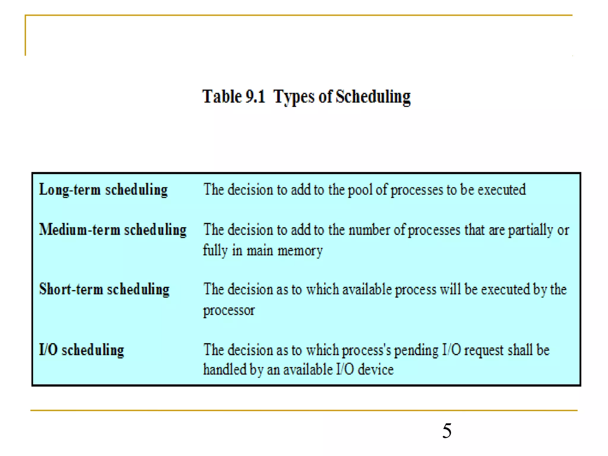
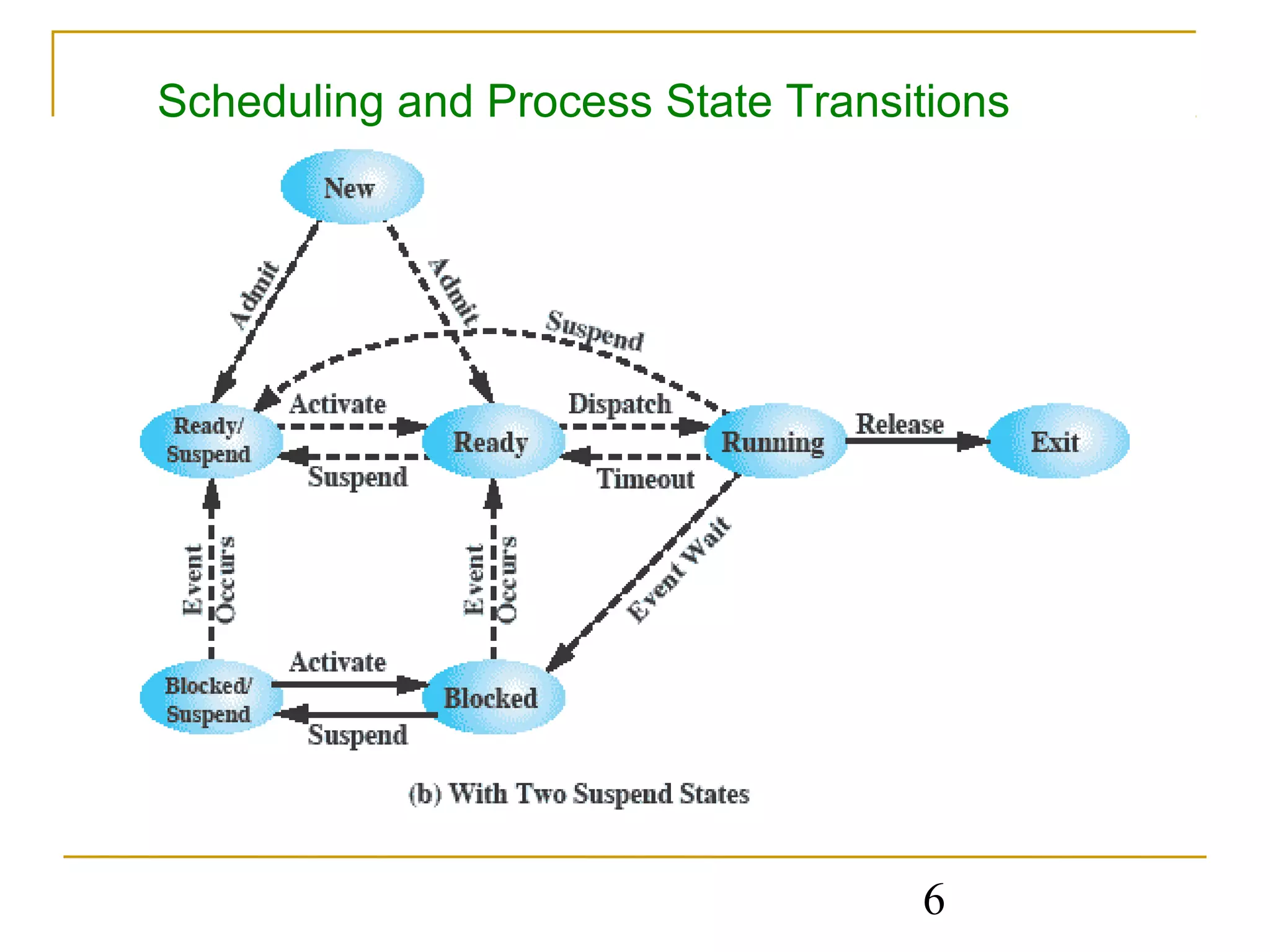
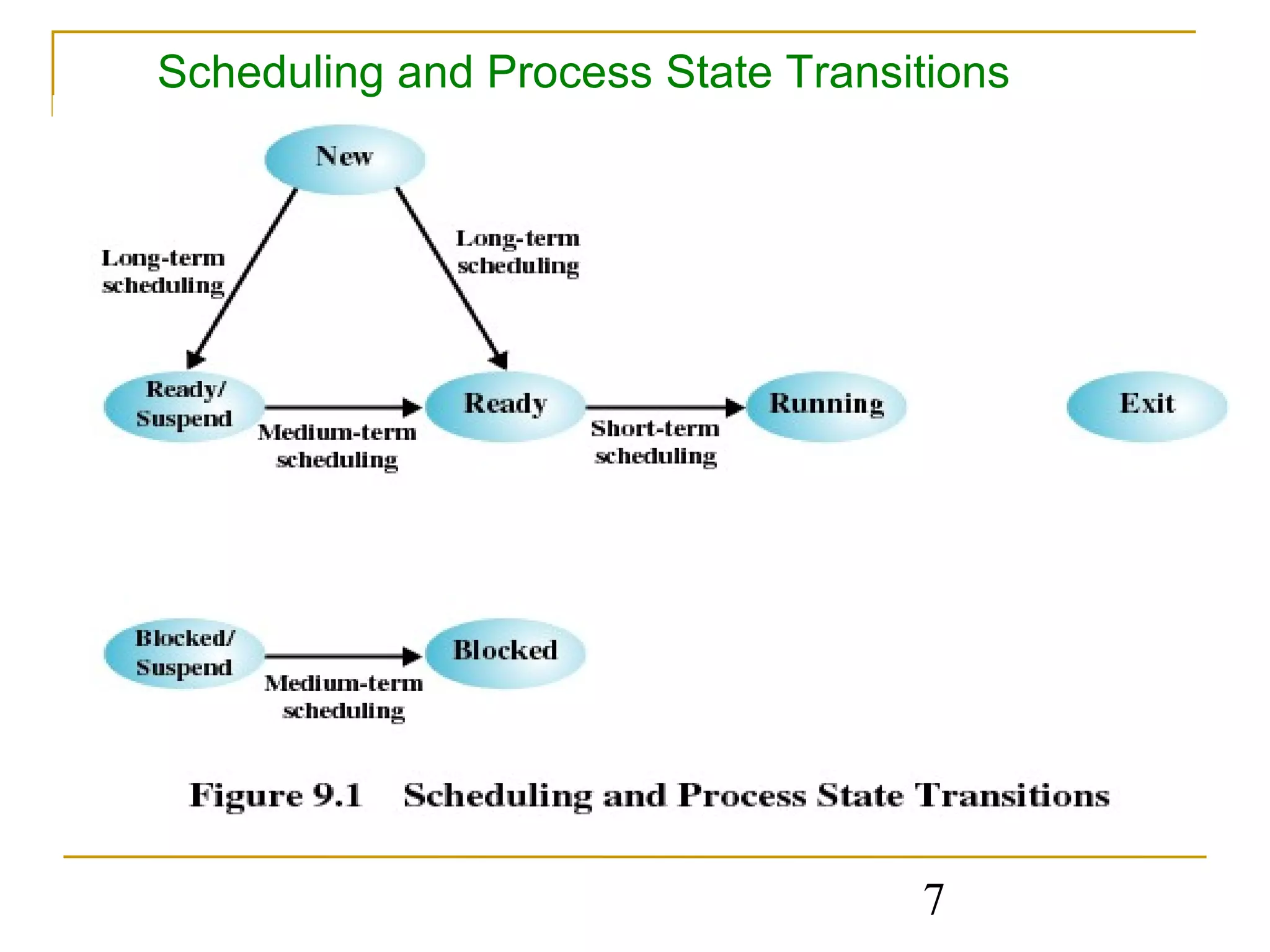
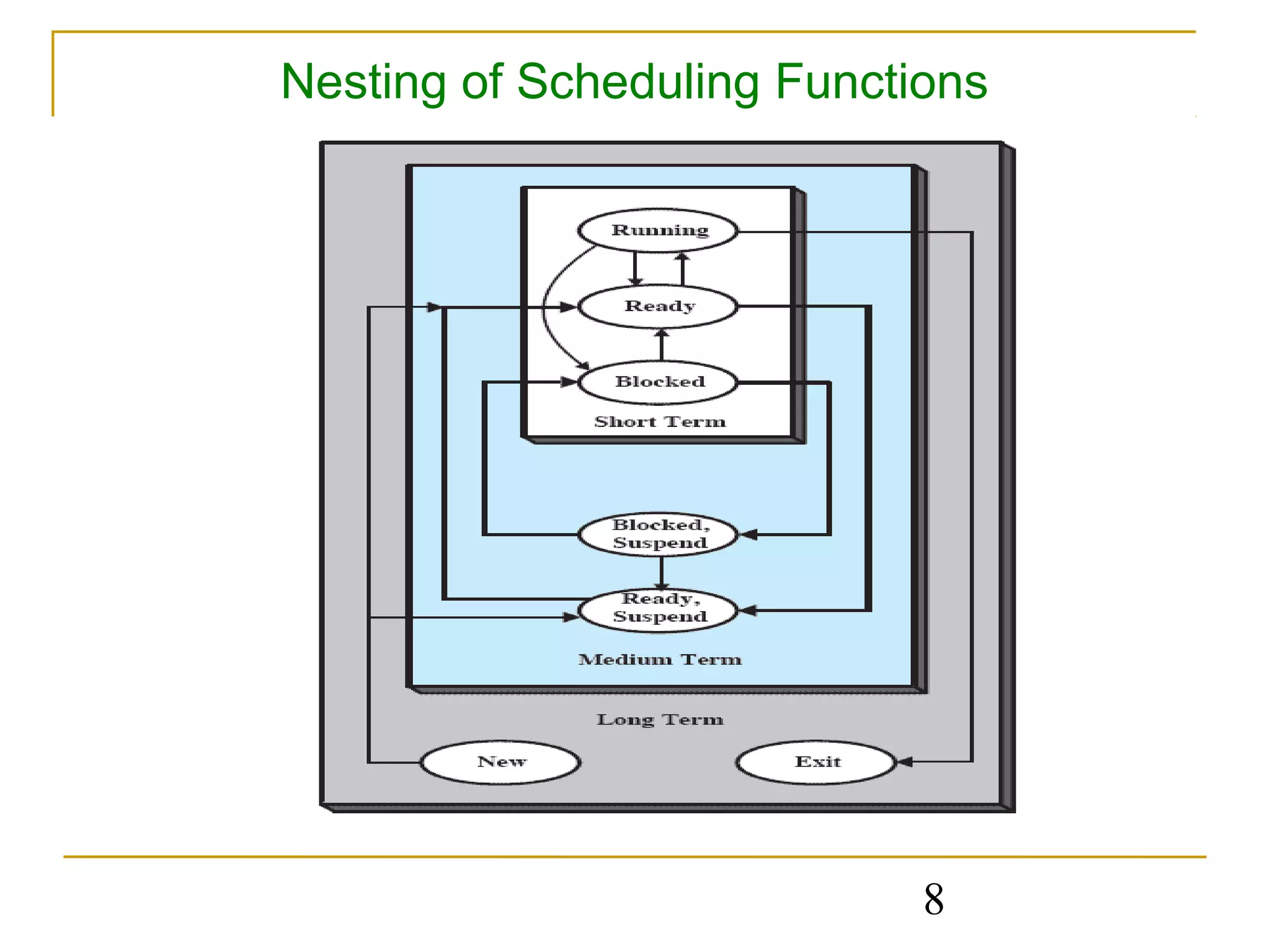
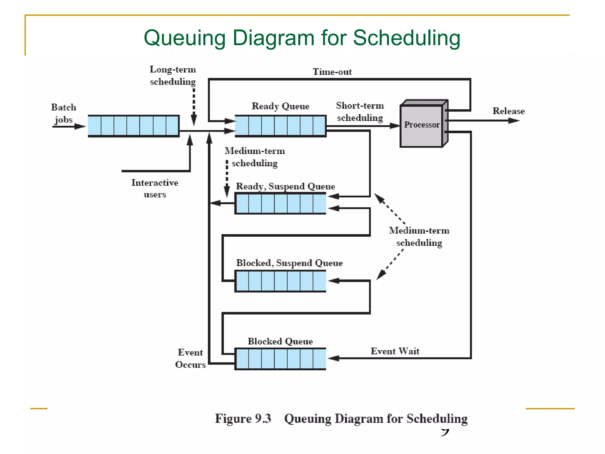
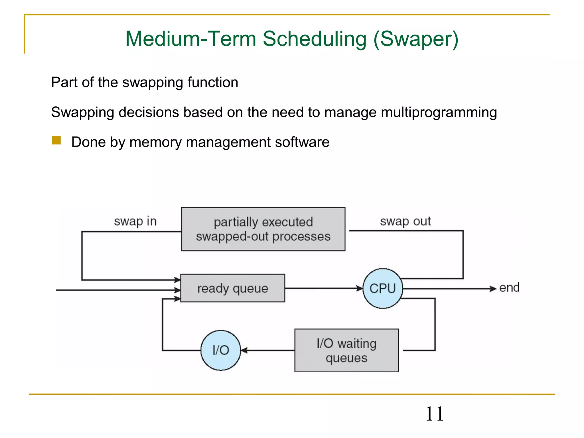
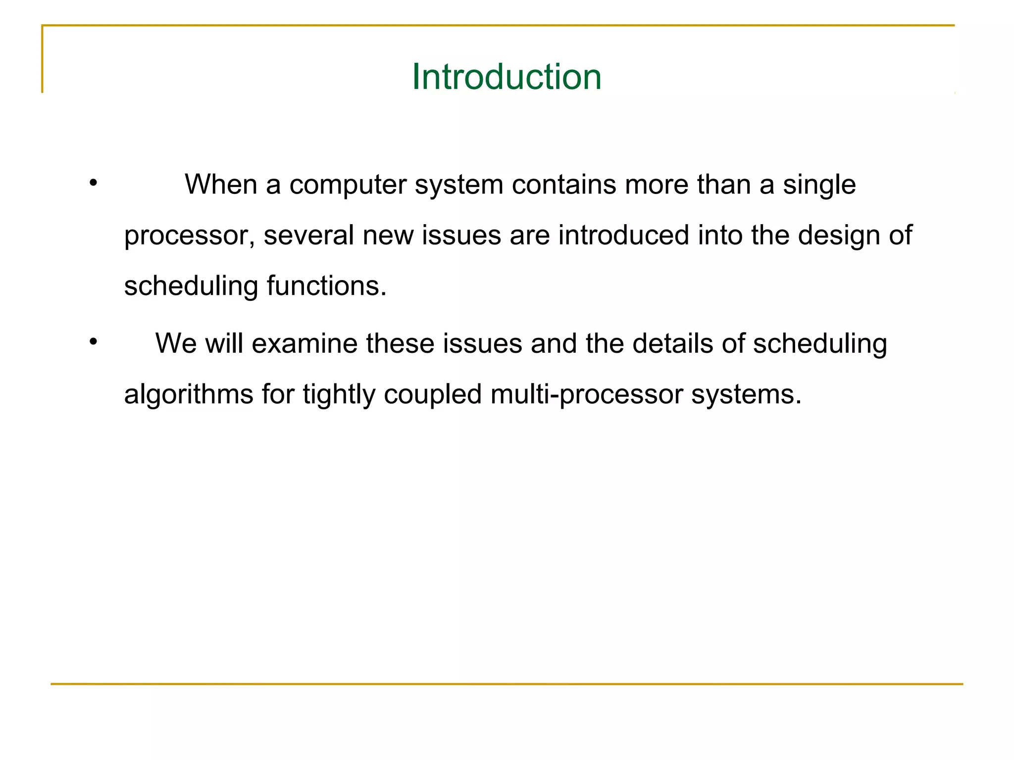
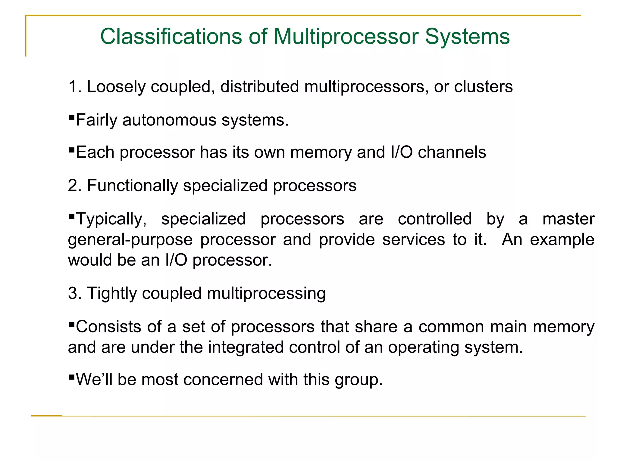
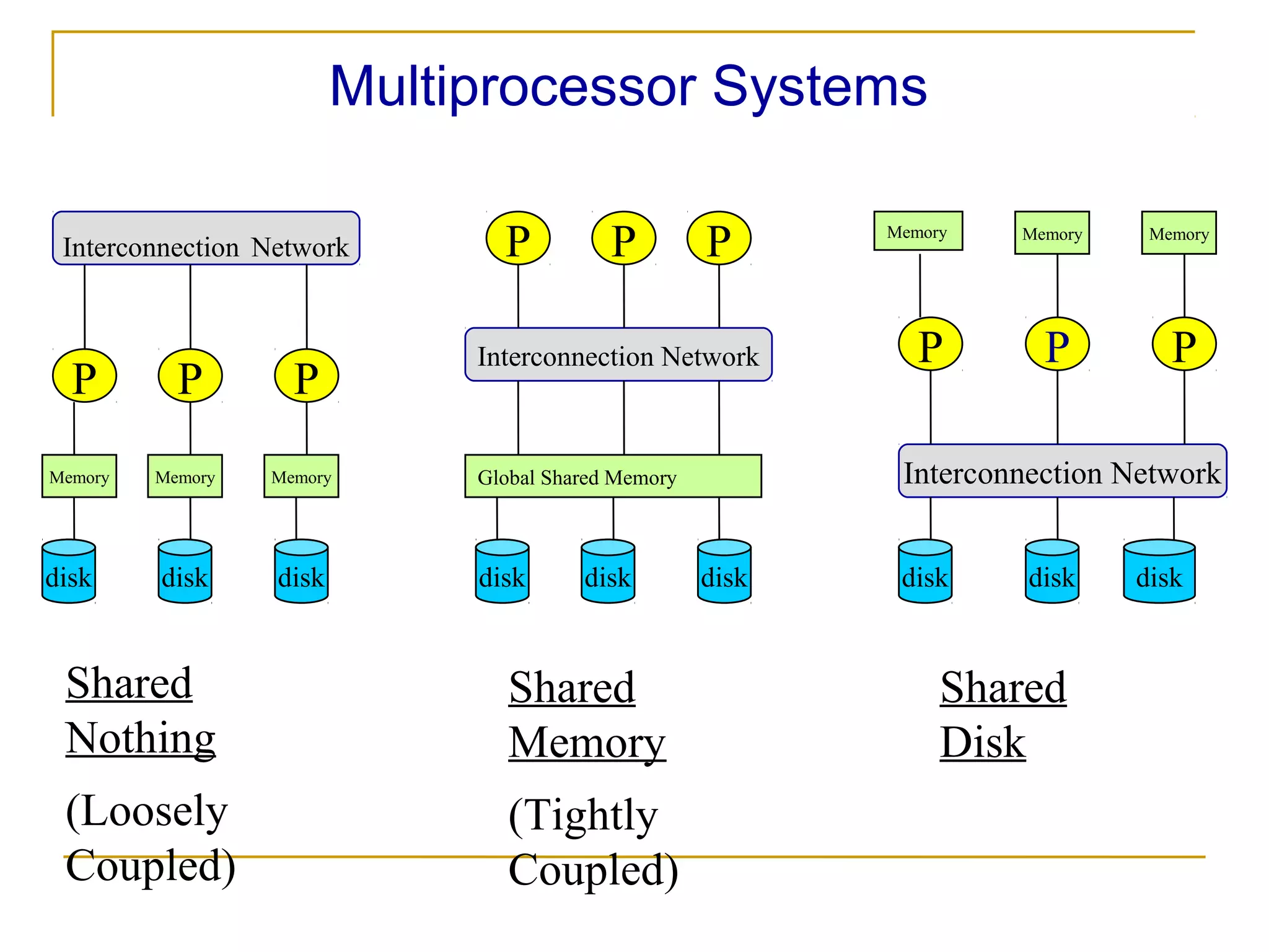
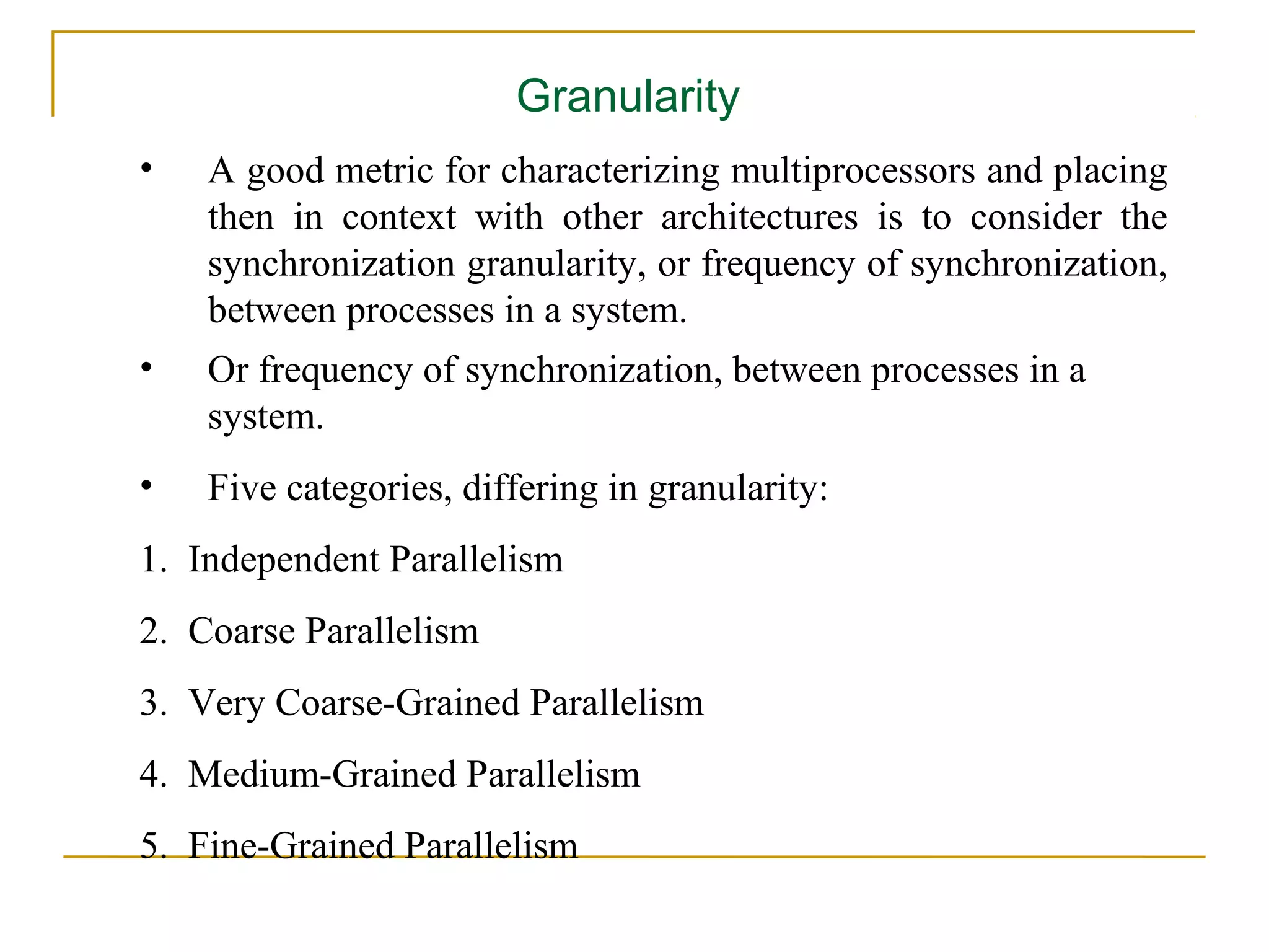
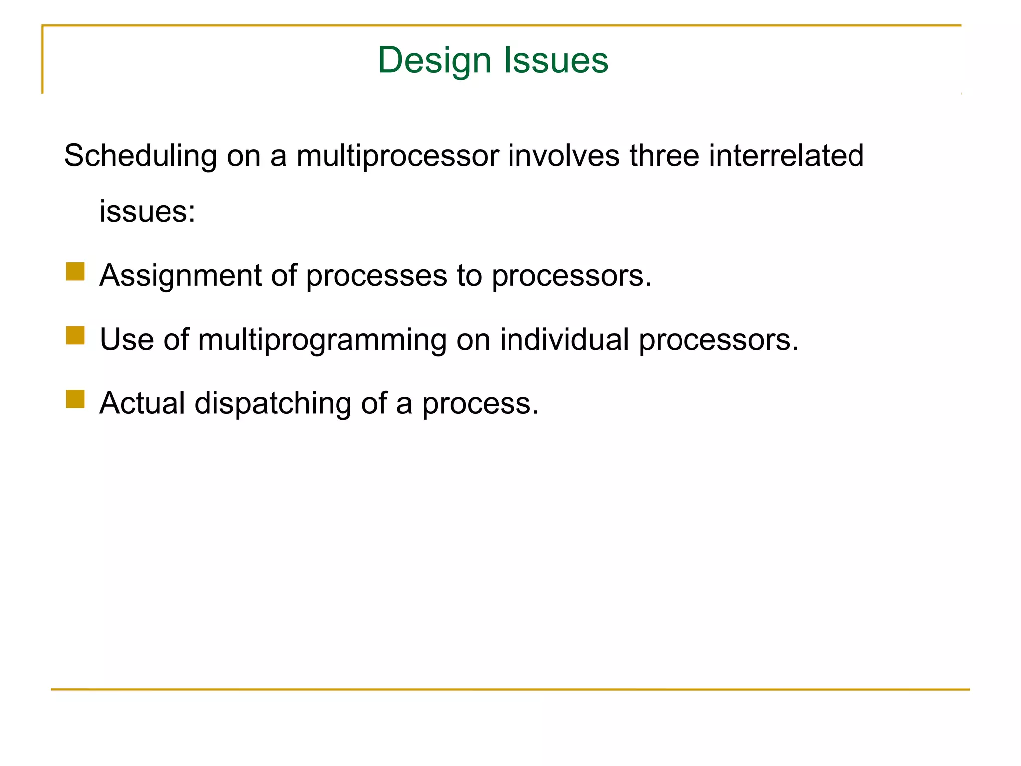
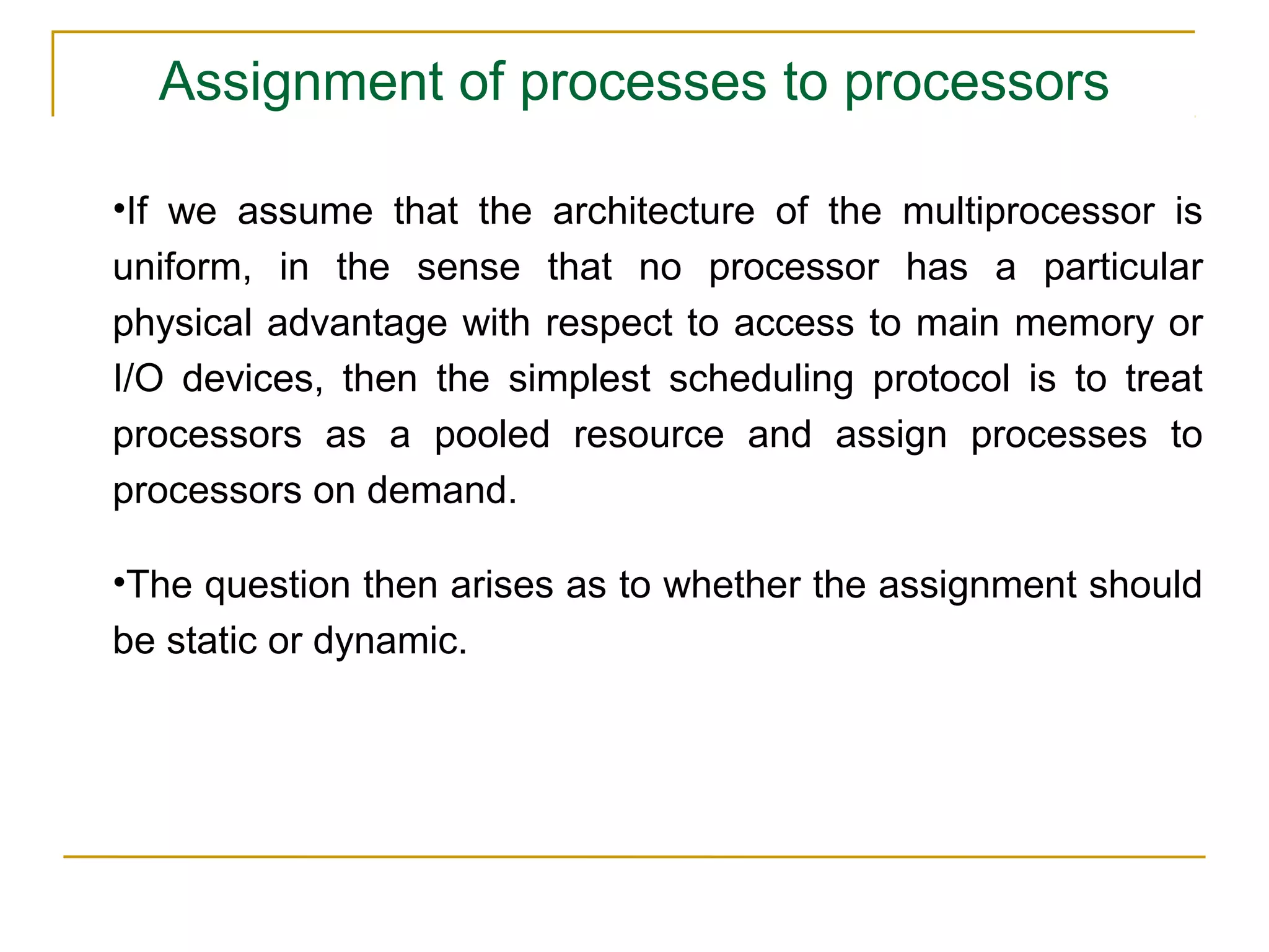
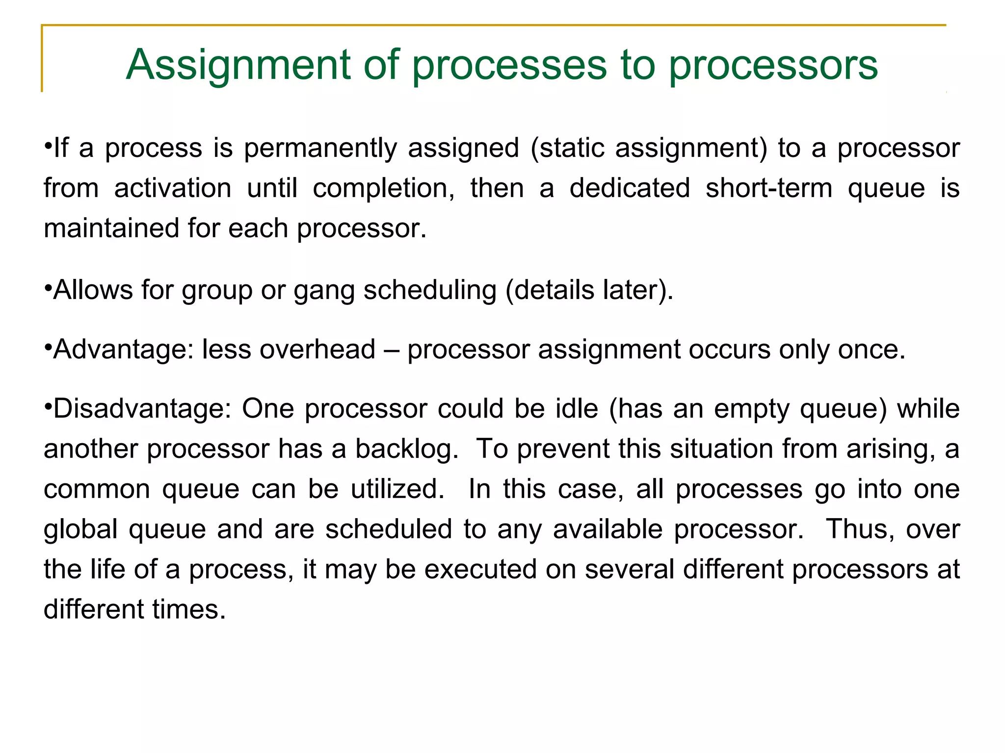
This document discusses various concepts related to scheduling in operating systems including: 1) Types of scheduling such as preemptive, non-preemptive, long-term, medium-term, and short-term. 2) Scheduling algorithms like FCFS, SJF, RR, and priority scheduling. 3) Issues in uniprocessor and multiprocessor scheduling including objectives, algorithms, and performance considerations. 4) The document provides examples and details on scheduling concepts.


![Vibe Coding vs. Spec-Driven Development [Free Meetup]](https://cdn.slidesharecdn.com/ss_thumbnails/vibecodingvsspecdrivendevelopment-251209105622-43f455e7-thumbnail.jpg?width=640&height=640&fit=bounds)


