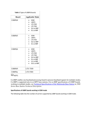
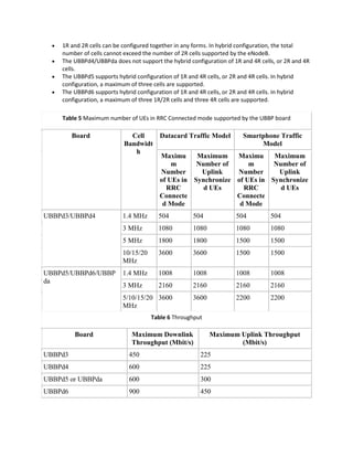
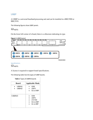
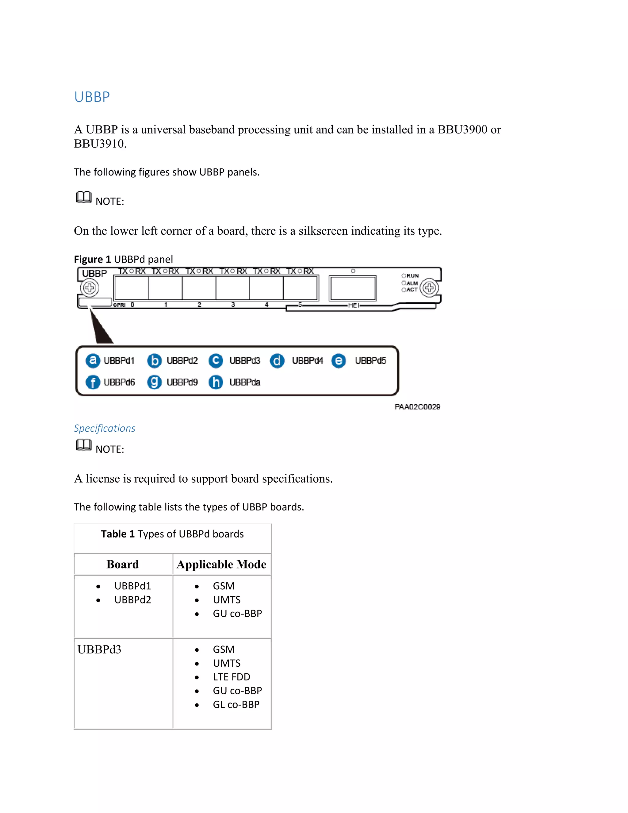
UBBP
A UBBP is a universal baseband processing unit and can be installed in a BBU3900 or
BBU3910.
The following figures show UBBP panels.
NOTE:
On the lower left corner of a board, there is a silkscreen indicating its type.
Figure 1 UBBPd panel
Specifications
NOTE:
A license is required to support board specifications.
The following table lists the types of UBBP boards.
Table 1 Types of UBBPd boards
Board Applicable Mode
 UBBPd1
 UBBPd2
 GSM
 UMTS
 GU co-BBP
UBBPd3  GSM
 UMTS
 LTE FDD
 GU co-BBP
 GL co-BBP
Table 1 Types of UBBPd boards
Board Applicable Mode
UBBPd4  GSM
 UMTS
 LTE FDD
 LTE TDD
 GU co-BBP
 GL co-BBP
UBBPd5  GSM
 UMTS
 LTE FDD
 GU co-BBP
 GL co-BBP
UBBPd6  GSM
 UMTS
 LTE FDD
 LTE TDD
 GU co-BBP
 GL co-BBP
 UL co-BBP
 GUL co-BBP
UBBPd9 LTE TDD
UBBPda LTE FDD
NOTE:
Co-BBP enables one baseband processing board to process baseband signals for multiple modes.
Co-BBP is supported only in co-MPT base stations. For co-BBP specifications of UBBP boards
working in multiple modes, see Technical Specifications of the Multimode Base Station in 3900
Series Base Station Technical Description.
Specifications of UBBP boards working in GSM mode
The following table lists the number of carriers supported by UBBP boards working in GSM mode.
Table 2 Carrier specifications
Board Number of 2R Carriers Number of 4R Carriers
UBBPd1, UBBPd2, UBBPd3,
or UBBPd4
24 12
UBBPd5 36 18
UBBPd6 48 24
Specifications of UBBP boards working in UMTS mode
Table 3 lists the baseband specifications of UBBP boards working in UMTS mode.
Table 3 Baseband specifications
Board Number of
Cellsa
Number of
Uplink
CEs
Number of
Downlink
CEs
Number of
HSDPA
Codes
Number of
HSDPA
UEs
Number of
HSUPA
UEs
UBBPd1 6 384 512 6x15 288 288
UBBPd2 6 512 768 6x15 384 384
UBBPd3 6 384 512 6x15 288 288
UBBPd4 6 512 768 6x15 384 384
UBBPd5 6 768 768 6x15 512 512
UBBPd6 12 1024 1024 12x15 768 768
NOTE:
For combined signaling specifications of a board, see section "Technical Specifications of the
BBU3900s and BBU3910s" in 3900 Series Base Station Technical Description.
Specifications of UBBP boards working in LTE FDD mode
Table 4, Table 5, and Table 6 list the specifications of cells, the maximum number of UEs in RRC
connected mode, and maximum uplink and downlink throughput supported by UBBP boards working in
LTE FDD mode, respectively. Table 7 lists the signaling specifications supported by UBBP boards working
in LTE FDD mode.
Table 4 Cell specifications of a UBBP
Board Number of Cells Cell Bandwidth
(MHz)
Antenna
Configuration
UBBPd3 3 1.4/3/5/10/15/20 3x20 MHz 1T1R
Table 4 Cell specifications of a UBBP
Board Number of Cells Cell Bandwidth
(MHz)
Antenna
Configuration
3x20 MHz 1T2R
3x20 MHz 2T2R
UBBPd4 3 1.4/3/5/10/15/20 3x20 MHz 1T1R
3x20 MHz 1T2R
3x20 MHz 2T2R
3x20 MHz 2T4R
3x20 MHz 4T4R
UBBPd5 6 1.4/3/5/10/15/20 6x20 MHz 1T1R
6x20 MHz 1T2R
6x20 MHz 2T2R
3x20 MHz 4T4R
UBBPd6 6 1.4/3/5/10/15/20 6x20 MHz 1T1R
6x20 MHz 1T2R
6x20 MHz 2T2R
6x20 MHz 2T4R
6x20 MHz 4T4R
UBBPda 6 1.4/3/5/10/15/20 6x10 MHz 2T4R
6x20 MHz 1T1R
6x20 MHz 1T2R
6x20 MHz 2T2R
NOTE:
 1R and 2R cells can be configured together in any forms. In hybrid configuration, the total
number of cells cannot exceed the number of 2R cells supported by the eNodeB.
 The UBBPd4/UBBPda does not support the hybrid configuration of 1R and 4R cells, or 2R and 4R
cells.
 The UBBPd5 supports hybrid configuration of 1R and 4R cells, or 2R and 4R cells. In hybrid
configuration, a maximum of three cells are supported.
 The UBBPd6 supports hybrid configuration of 1R and 4R cells, or 2R and 4R cells. In hybrid
configuration, a maximum of three 1R/2R cells and three 4R cells are supported.
Table 5 Maximum number of UEs in RRC Connected mode supported by the UBBP board
Board Cell
Bandwidt
h
Datacard Traffic Model Smartphone Traffic
Model
Maximu
m
Number
of UEs in
RRC
Connecte
d Mode
Maximum
Number of
Uplink
Synchronize
d UEs
Maximu
m
Number
of UEs in
RRC
Connecte
d Mode
Maximum
Number of
Uplink
Synchronize
d UEs
UBBPd3/UBBPd4 1.4 MHz 504 504 504 504
3 MHz 1080 1080 1080 1080
5 MHz 1800 1800 1500 1500
10/15/20
MHz
3600 3600 1500 1500
UBBPd5/UBBPd6/UBBP
da
1.4 MHz 1008 1008 1008 1008
3 MHz 2160 2160 2160 2160
5/10/15/20
MHz
3600 3600 2200 2200
Table 6 Throughput
Board Maximum Downlink
Throughput (Mbit/s)
Maximum Uplink Throughput
(Mbit/s)
UBBPd3 450 225
UBBPd4 600 225
UBBPd5 or UBBPda 600 300
UBBPd6 900 450
Table 7 Signaling specifications
Board Signaling Specifications (BHCA)a
UBBPd3/UBBPd4 270000
UBBPd5/UBBPd6/UBBPda 396000
a: The BHCA specifications are based on the smart device traffic model.
The maximum number of data radio bearers (DRBs) supported by a UBBP is three times the maximum
number of UEs in RRC connected mode based on the datacard traffic model.
Specifications of UBBP boards working in LTE TDD mode
Table 8, Table 9, Table 10, and Table 11 list the specifications of cells, maximum number of UEs in RRC
connected mode, maximum uplink and downlink throughput, and signaling specifications supported by
UBBP boards working in LTE TDD mode, respectively.
Table 8 Cell specifications of a UBBP
Board Number of Cells Cell Bandwidth
(MHz)
Antenna
Configuration
UBBPd4 3 5/10/15/20 3x20 MHz 2T2R
3x20 MHz 4T4R
UBBPd6 6 5/10/15/20 6x20 MHz 2T2R
6x20 MHz 4T4R
UBBPd9 3 10/15/20 3x20 MHz 8T8R
Table 9 Maximum number of UEs in RRC Connected mode supported by the UBBP board
Board Cell
Bandwidth
Maximum Number
of UEs in RRC
Connected Mode
(Datacard Traffic
Model)
Maximum Number of UEs in RRC
Connected Mode (Smartphone Traffic
Model)
UBBPd4 5 MHz 1800 900
10/15/20
MHz
3600 1500
UBBPd6 5 MHz 1800 1800
10/15/20
MHz
3600 2200
Table 8 Cell specifications of a UBBP
Board Number of Cells Cell Bandwidth
(MHz)
Antenna
Configuration
UBBPd9 10 MHz 3600 1800
15/20 MHz 3600 2200
Table 10 Throughput
Board Maximum Downlink
Throughput (Mbit/s)
Maximum Uplink
Throughput (Mbit/s)
UBBPd4 600 225
UBBPd6 900 450
UBBPd9  660 with a subframe
configuration of SA1
 720 with a subframe
configuration of SA2
 350 with a subframe
configuration of SA1
 420 with a subframe
configuration of SA2
Table 11 Signaling specifications
Board Signaling Specifications (BHCA)
UBBPd4 270000
UBBPd6 or UBBPd9 396000
NOTE:
The signaling specifications for TDD scenarios are the maximum ones for typical scenarios of
normal cells.
The maximum number of DRBs supported by a UBBP is three times the maximum number of
UEs in RRC connected mode.
NOTE:
For specifications of an eNodeB, see section "Technical Specifications of the BBU3900s and BBU3910s"
in 3900 Series Base Station Technical Description.
Function
A UBBP performs the following functions:
 Provides CPRI ports for communication with RF modules.
 Processes uplink and downlink baseband signals.
 Supports the multiplex of baseband resources among different modes, thereby implementing
multimode concurrency.
Working Principle
The following figure shows the working principle of a UBBP.
Figure 2 Working principle of a UBBP
Port
The following table describes the six CPRI ports and one HEI port on a UBBP.
Table 12 Ports on a UBBP
Silkscreen Connector Quantity of Ports Description
CPRI0 to CPRI5 SFP female connector 6 They are data
transmission ports
connecting BBUs to
RF modules, and
support input and
output of optical and
electrical signals.
HEI QSFP connector 1 It interconnects to
other baseband
processing boards to
share baseband
resources.
The following table lists the specifications of CPRI ports on a UBBP.
Table 13 Specifications of CPRI ports on a UBBP
Board Quantity of CPRI
Ports
CPRI Port Rate
(Gbit/s)
Topology Type
UBBPd 6 1.25, 2.5, 4.9, 9.8, or
6.144
Star, chain, and ring
topologies
The following table lists the mapping between the CPRI port rate and the number of carriers supported
by a UBBP working in GSM mode.
Table 14 Mapping between the CPRI port rate and the number of carriers
CPRI Port Rate (Gbit/s) Number of 1T2R Carriers Number of 2T2R or 1T4R
Carriers
1.25 24 12
2.5 48 24
4.9 48 24
9.8 48 24
The following table lists the mapping between the CPRI port rate and the number of cells supported by a
UBBP working in UMTS mode.
Table 15 Mapping between the CPRI port rate and the number of cells in UMTS scenarios
CPRI Port Rate (Gbit/s) Number of 1T2R Cells Number of 2T2R Cells
1.25 4 4*a
2.5 8 8*a
4.9 16 16*a
6.144 24 24*a
9.8 32 32*a
a: The asterisk (*) in the table indicates that the number of 2T2R cells is halved if the 2T2R
cells support the virtual antenna mapping (VAM) function and the two TX antennas used by
the VAM function are separately connected to two RF modules carried on different CPRI links.
The following table lists the mapping between the CPRI port rate and the number of cells supported by a
UBBP working in LTE FDD mode.
Table 16 Mapping between the CPRI port rate and the number of cells in an LTE FDD scenario
CPRI Port Rate
(Gbit/s)
Number of 2T4R or
4T4R Cells
Number of 1T2R or
2T2R Cells
Number of 1T1R
Cells
1.25 4x4 MIMO cells are
not recommended
because the
transmission
bandwidth of CPRI
ports is limited.
 4 (cell
bandwidth ≤ 3
MHz)
 2 (cell
bandwidth ≤ 5
MHz)
 1 (cell
bandwidth ≤ 10
MHz)
 8 (cell
bandwidth ≤ 3
MHz)
 4 (cell
bandwidth ≤ 5
MHz)
 2 (cell
bandwidth ≤ 10
MHz)
 1 (cell
bandwidth = 15
MHz or 20 MHz)
2.5 1 (cell bandwidth ≤ 10
MHz)
 4 (cell
bandwidth ≤ 5
MHz)
 2 (cell
bandwidth ≤ 10
MHz)
 1 (cell
bandwidth = 15
MHz or 20 MHz)
 8 (cell
bandwidth ≤ 5
MHz)
 4 (cell
bandwidth ≤ 10
MHz)
 2 (cell
bandwidth = 15
MHz or 20 MHz)
4.9  2 (cell
bandwidth ≤ 10
MHz)
 1 (cell
bandwidth = 15
MHz or 20 MHz)
 4 (cell
bandwidth ≤ 10
MHz)
 2 (cell
bandwidth = 15
MHz or 20 MHz)
 8 (cell
bandwidth ≤ 10
MHz)
 4 (cell
bandwidth = 15
MHz or 20 MHz)
6.144  2 (cell
bandwidth ≤ 10
MHz)
 1 (cell
bandwidth = 15
MHz or 20 MHz)
 5 (cell
bandwidth ≤ 10
MHz)
 2 (cell
bandwidth = 15
MHz or 20 MHz)
 10 (cell
bandwidth ≤ 10
MHz)
 5 (cell
bandwidth = 15
MHz or 20 MHz)
9.8  4 (cell
bandwidth ≤ 10
MHz)
 8 (cell
bandwidth ≤ 10
MHz)
 16 (cell
bandwidth ≤ 10
MHz)
Table 16 Mapping between the CPRI port rate and the number of cells in an LTE FDD scenario
CPRI Port Rate
(Gbit/s)
Number of 2T4R or
4T4R Cells
Number of 1T2R or
2T2R Cells
Number of 1T1R
Cells
 2 (cell
bandwidth = 15
MHz or 20 MHz)
 4 (cell
bandwidth = 15
MHz or 20 MHz)
 8 (cell
bandwidth = 15
MHz or 20 MHz)
The following table lists the mapping between the CPRI port rate and the number of cells supported by a
UBBP working in LTE TDD mode.
Table 17 Mapping between the CPRI port rate and the number of cells in an LTE TDD scenario
CPRI Port Rate
(Gbit/s)
CPRI
Compression
Number of
8T8R Cells
Number of
4T4R Cells
Number of
2T2R Cells
2.5 Not in use None  2 (cell
bandwidth
= 5 MHz)
 1 (cell
bandwidth
= 10 MHz)
 None (cell
bandwidth
= 15 MHz
or 20 MHz)
 4 (cell
bandwidth
= 5 MHz)
 2 (cell
bandwidth
= 10 MHz)
 1 (cell
bandwidth
= 15 MHz
or 20 MHz)
In use None  None (cell
bandwidth
= 5 MHz)
 1 (cell
bandwidth
= 10 MHz)
 1 (cell
bandwidth
= 15 MHz
or 20 MHz)
 None (cell
bandwidth
= 5 MHz)
 3 (cell
bandwidth
= 10 MHz)
 2 (cell
bandwidth
= 15 MHz
or 20 MHz)
4.9 Not in use  None (cell
bandwidth
= 5 MHz)
 1 (cell
bandwidth
= 10 MHz)
 4 (cell
bandwidth
= 5 MHz)
 2 (cell
bandwidth
= 10 MHz)
 8 (cell
bandwidth
= 5 MHz)
 4 (cell
bandwidth
= 10 MHz)
Table 17 Mapping between the CPRI port rate and the number of cells in an LTE TDD scenario
CPRI Port Rate
(Gbit/s)
CPRI
Compression
Number of
8T8R Cells
Number of
4T4R Cells
Number of
2T2R Cells
 None (cell
bandwidth
= 15 MHz
or 20 MHz)
 1 (cell
bandwidth
= 15 MHz
or 20 MHz)
 2 (cell
bandwidth
= 15 MHz
or 20 MHz)
In use  None (cell
bandwidth
= 5 MHz)
 1 (cell
bandwidth
= 10 MHz)
 1 (cell
bandwidth
= 15 MHz
or 20 MHz)
 None (cell
bandwidth
= 5 MHz)
 3 (cell
bandwidth
= 10 MHz)
 2 (cell
bandwidth
= 15 MHz
or 20 MHz)
 None (cell
bandwidth
= 5 MHz)
 6 (cell
bandwidth
= 10 MHz)
 4 (cell
bandwidth
= 15 MHz
or 20 MHz)
9.8 Not in use  None (cell
bandwidth
= 5 MHz)
 2 (cell
bandwidth
= 10 MHz)
 1 (cell
bandwidth
= 15 MHz
or 20 MHz)
 8 (cell
bandwidth
= 5 MHz)
 4 (cell
bandwidth
= 10 MHz)
 2 (cell
bandwidth
= 15 MHz
or 20 MHz)
 16 (cell
bandwidth
= 5 MHz)
 8 (cell
bandwidth
= 10 MHz)
 4 (cell
bandwidth
= 15 MHz
or 20 MHz)
In use  None (cell
bandwidth
= 5 MHz or
15 MHz)
 3 (cell
bandwidth
= 10 MHz)
 2 (cell
bandwidth
= 20 MHz)
 None (cell
bandwidth
= 5 MHz or
15 MHz)
 6 (cell
bandwidth
= 10 MHz)
 4 (cell
bandwidth
= 20 MHz)
 None (cell
bandwidth
= 5 MHz or
15 MHz)
 12 (cell
bandwidth
= 10 MHz)
 8 (cell
bandwidth
= 20 MHz)
Parent topic: BBU3900 and BBU3910 Boards
Huawei Proprietary and Confidential
Copyright Š Huawei Technologies Co., Ltd.

Ubbp

  • 1.
    UBBP A UBBP isa universal baseband processing unit and can be installed in a BBU3900 or BBU3910. The following figures show UBBP panels. NOTE: On the lower left corner of a board, there is a silkscreen indicating its type. Figure 1 UBBPd panel Specifications NOTE: A license is required to support board specifications. The following table lists the types of UBBP boards. Table 1 Types of UBBPd boards Board Applicable Mode  UBBPd1  UBBPd2  GSM  UMTS  GU co-BBP UBBPd3  GSM  UMTS  LTE FDD  GU co-BBP  GL co-BBP
  • 2.
    Table 1 Typesof UBBPd boards Board Applicable Mode UBBPd4  GSM  UMTS  LTE FDD  LTE TDD  GU co-BBP  GL co-BBP UBBPd5  GSM  UMTS  LTE FDD  GU co-BBP  GL co-BBP UBBPd6  GSM  UMTS  LTE FDD  LTE TDD  GU co-BBP  GL co-BBP  UL co-BBP  GUL co-BBP UBBPd9 LTE TDD UBBPda LTE FDD NOTE: Co-BBP enables one baseband processing board to process baseband signals for multiple modes. Co-BBP is supported only in co-MPT base stations. For co-BBP specifications of UBBP boards working in multiple modes, see Technical Specifications of the Multimode Base Station in 3900 Series Base Station Technical Description. Specifications of UBBP boards working in GSM mode The following table lists the number of carriers supported by UBBP boards working in GSM mode.
  • 3.
    Table 2 Carrierspecifications Board Number of 2R Carriers Number of 4R Carriers UBBPd1, UBBPd2, UBBPd3, or UBBPd4 24 12 UBBPd5 36 18 UBBPd6 48 24 Specifications of UBBP boards working in UMTS mode Table 3 lists the baseband specifications of UBBP boards working in UMTS mode. Table 3 Baseband specifications Board Number of Cellsa Number of Uplink CEs Number of Downlink CEs Number of HSDPA Codes Number of HSDPA UEs Number of HSUPA UEs UBBPd1 6 384 512 6x15 288 288 UBBPd2 6 512 768 6x15 384 384 UBBPd3 6 384 512 6x15 288 288 UBBPd4 6 512 768 6x15 384 384 UBBPd5 6 768 768 6x15 512 512 UBBPd6 12 1024 1024 12x15 768 768 NOTE: For combined signaling specifications of a board, see section "Technical Specifications of the BBU3900s and BBU3910s" in 3900 Series Base Station Technical Description. Specifications of UBBP boards working in LTE FDD mode Table 4, Table 5, and Table 6 list the specifications of cells, the maximum number of UEs in RRC connected mode, and maximum uplink and downlink throughput supported by UBBP boards working in LTE FDD mode, respectively. Table 7 lists the signaling specifications supported by UBBP boards working in LTE FDD mode. Table 4 Cell specifications of a UBBP Board Number of Cells Cell Bandwidth (MHz) Antenna Configuration UBBPd3 3 1.4/3/5/10/15/20 3x20 MHz 1T1R
  • 4.
    Table 4 Cellspecifications of a UBBP Board Number of Cells Cell Bandwidth (MHz) Antenna Configuration 3x20 MHz 1T2R 3x20 MHz 2T2R UBBPd4 3 1.4/3/5/10/15/20 3x20 MHz 1T1R 3x20 MHz 1T2R 3x20 MHz 2T2R 3x20 MHz 2T4R 3x20 MHz 4T4R UBBPd5 6 1.4/3/5/10/15/20 6x20 MHz 1T1R 6x20 MHz 1T2R 6x20 MHz 2T2R 3x20 MHz 4T4R UBBPd6 6 1.4/3/5/10/15/20 6x20 MHz 1T1R 6x20 MHz 1T2R 6x20 MHz 2T2R 6x20 MHz 2T4R 6x20 MHz 4T4R UBBPda 6 1.4/3/5/10/15/20 6x10 MHz 2T4R 6x20 MHz 1T1R 6x20 MHz 1T2R 6x20 MHz 2T2R NOTE:
  • 5.
     1R and2R cells can be configured together in any forms. In hybrid configuration, the total number of cells cannot exceed the number of 2R cells supported by the eNodeB.  The UBBPd4/UBBPda does not support the hybrid configuration of 1R and 4R cells, or 2R and 4R cells.  The UBBPd5 supports hybrid configuration of 1R and 4R cells, or 2R and 4R cells. In hybrid configuration, a maximum of three cells are supported.  The UBBPd6 supports hybrid configuration of 1R and 4R cells, or 2R and 4R cells. In hybrid configuration, a maximum of three 1R/2R cells and three 4R cells are supported. Table 5 Maximum number of UEs in RRC Connected mode supported by the UBBP board Board Cell Bandwidt h Datacard Traffic Model Smartphone Traffic Model Maximu m Number of UEs in RRC Connecte d Mode Maximum Number of Uplink Synchronize d UEs Maximu m Number of UEs in RRC Connecte d Mode Maximum Number of Uplink Synchronize d UEs UBBPd3/UBBPd4 1.4 MHz 504 504 504 504 3 MHz 1080 1080 1080 1080 5 MHz 1800 1800 1500 1500 10/15/20 MHz 3600 3600 1500 1500 UBBPd5/UBBPd6/UBBP da 1.4 MHz 1008 1008 1008 1008 3 MHz 2160 2160 2160 2160 5/10/15/20 MHz 3600 3600 2200 2200 Table 6 Throughput Board Maximum Downlink Throughput (Mbit/s) Maximum Uplink Throughput (Mbit/s) UBBPd3 450 225 UBBPd4 600 225 UBBPd5 or UBBPda 600 300 UBBPd6 900 450
  • 6.
    Table 7 Signalingspecifications Board Signaling Specifications (BHCA)a UBBPd3/UBBPd4 270000 UBBPd5/UBBPd6/UBBPda 396000 a: The BHCA specifications are based on the smart device traffic model. The maximum number of data radio bearers (DRBs) supported by a UBBP is three times the maximum number of UEs in RRC connected mode based on the datacard traffic model. Specifications of UBBP boards working in LTE TDD mode Table 8, Table 9, Table 10, and Table 11 list the specifications of cells, maximum number of UEs in RRC connected mode, maximum uplink and downlink throughput, and signaling specifications supported by UBBP boards working in LTE TDD mode, respectively. Table 8 Cell specifications of a UBBP Board Number of Cells Cell Bandwidth (MHz) Antenna Configuration UBBPd4 3 5/10/15/20 3x20 MHz 2T2R 3x20 MHz 4T4R UBBPd6 6 5/10/15/20 6x20 MHz 2T2R 6x20 MHz 4T4R UBBPd9 3 10/15/20 3x20 MHz 8T8R Table 9 Maximum number of UEs in RRC Connected mode supported by the UBBP board Board Cell Bandwidth Maximum Number of UEs in RRC Connected Mode (Datacard Traffic Model) Maximum Number of UEs in RRC Connected Mode (Smartphone Traffic Model) UBBPd4 5 MHz 1800 900 10/15/20 MHz 3600 1500 UBBPd6 5 MHz 1800 1800 10/15/20 MHz 3600 2200
  • 7.
    Table 8 Cellspecifications of a UBBP Board Number of Cells Cell Bandwidth (MHz) Antenna Configuration UBBPd9 10 MHz 3600 1800 15/20 MHz 3600 2200 Table 10 Throughput Board Maximum Downlink Throughput (Mbit/s) Maximum Uplink Throughput (Mbit/s) UBBPd4 600 225 UBBPd6 900 450 UBBPd9  660 with a subframe configuration of SA1  720 with a subframe configuration of SA2  350 with a subframe configuration of SA1  420 with a subframe configuration of SA2 Table 11 Signaling specifications Board Signaling Specifications (BHCA) UBBPd4 270000 UBBPd6 or UBBPd9 396000 NOTE: The signaling specifications for TDD scenarios are the maximum ones for typical scenarios of normal cells. The maximum number of DRBs supported by a UBBP is three times the maximum number of UEs in RRC connected mode. NOTE: For specifications of an eNodeB, see section "Technical Specifications of the BBU3900s and BBU3910s" in 3900 Series Base Station Technical Description. Function A UBBP performs the following functions:  Provides CPRI ports for communication with RF modules.  Processes uplink and downlink baseband signals.
  • 8.
     Supports themultiplex of baseband resources among different modes, thereby implementing multimode concurrency. Working Principle The following figure shows the working principle of a UBBP. Figure 2 Working principle of a UBBP Port The following table describes the six CPRI ports and one HEI port on a UBBP. Table 12 Ports on a UBBP Silkscreen Connector Quantity of Ports Description CPRI0 to CPRI5 SFP female connector 6 They are data transmission ports connecting BBUs to RF modules, and support input and output of optical and electrical signals. HEI QSFP connector 1 It interconnects to other baseband processing boards to share baseband resources. The following table lists the specifications of CPRI ports on a UBBP.
  • 9.
    Table 13 Specificationsof CPRI ports on a UBBP Board Quantity of CPRI Ports CPRI Port Rate (Gbit/s) Topology Type UBBPd 6 1.25, 2.5, 4.9, 9.8, or 6.144 Star, chain, and ring topologies The following table lists the mapping between the CPRI port rate and the number of carriers supported by a UBBP working in GSM mode. Table 14 Mapping between the CPRI port rate and the number of carriers CPRI Port Rate (Gbit/s) Number of 1T2R Carriers Number of 2T2R or 1T4R Carriers 1.25 24 12 2.5 48 24 4.9 48 24 9.8 48 24 The following table lists the mapping between the CPRI port rate and the number of cells supported by a UBBP working in UMTS mode. Table 15 Mapping between the CPRI port rate and the number of cells in UMTS scenarios CPRI Port Rate (Gbit/s) Number of 1T2R Cells Number of 2T2R Cells 1.25 4 4*a 2.5 8 8*a 4.9 16 16*a 6.144 24 24*a 9.8 32 32*a a: The asterisk (*) in the table indicates that the number of 2T2R cells is halved if the 2T2R cells support the virtual antenna mapping (VAM) function and the two TX antennas used by the VAM function are separately connected to two RF modules carried on different CPRI links. The following table lists the mapping between the CPRI port rate and the number of cells supported by a UBBP working in LTE FDD mode.
  • 10.
    Table 16 Mappingbetween the CPRI port rate and the number of cells in an LTE FDD scenario CPRI Port Rate (Gbit/s) Number of 2T4R or 4T4R Cells Number of 1T2R or 2T2R Cells Number of 1T1R Cells 1.25 4x4 MIMO cells are not recommended because the transmission bandwidth of CPRI ports is limited.  4 (cell bandwidth ≤ 3 MHz)  2 (cell bandwidth ≤ 5 MHz)  1 (cell bandwidth ≤ 10 MHz)  8 (cell bandwidth ≤ 3 MHz)  4 (cell bandwidth ≤ 5 MHz)  2 (cell bandwidth ≤ 10 MHz)  1 (cell bandwidth = 15 MHz or 20 MHz) 2.5 1 (cell bandwidth ≤ 10 MHz)  4 (cell bandwidth ≤ 5 MHz)  2 (cell bandwidth ≤ 10 MHz)  1 (cell bandwidth = 15 MHz or 20 MHz)  8 (cell bandwidth ≤ 5 MHz)  4 (cell bandwidth ≤ 10 MHz)  2 (cell bandwidth = 15 MHz or 20 MHz) 4.9  2 (cell bandwidth ≤ 10 MHz)  1 (cell bandwidth = 15 MHz or 20 MHz)  4 (cell bandwidth ≤ 10 MHz)  2 (cell bandwidth = 15 MHz or 20 MHz)  8 (cell bandwidth ≤ 10 MHz)  4 (cell bandwidth = 15 MHz or 20 MHz) 6.144  2 (cell bandwidth ≤ 10 MHz)  1 (cell bandwidth = 15 MHz or 20 MHz)  5 (cell bandwidth ≤ 10 MHz)  2 (cell bandwidth = 15 MHz or 20 MHz)  10 (cell bandwidth ≤ 10 MHz)  5 (cell bandwidth = 15 MHz or 20 MHz) 9.8  4 (cell bandwidth ≤ 10 MHz)  8 (cell bandwidth ≤ 10 MHz)  16 (cell bandwidth ≤ 10 MHz)
  • 11.
    Table 16 Mappingbetween the CPRI port rate and the number of cells in an LTE FDD scenario CPRI Port Rate (Gbit/s) Number of 2T4R or 4T4R Cells Number of 1T2R or 2T2R Cells Number of 1T1R Cells  2 (cell bandwidth = 15 MHz or 20 MHz)  4 (cell bandwidth = 15 MHz or 20 MHz)  8 (cell bandwidth = 15 MHz or 20 MHz) The following table lists the mapping between the CPRI port rate and the number of cells supported by a UBBP working in LTE TDD mode. Table 17 Mapping between the CPRI port rate and the number of cells in an LTE TDD scenario CPRI Port Rate (Gbit/s) CPRI Compression Number of 8T8R Cells Number of 4T4R Cells Number of 2T2R Cells 2.5 Not in use None  2 (cell bandwidth = 5 MHz)  1 (cell bandwidth = 10 MHz)  None (cell bandwidth = 15 MHz or 20 MHz)  4 (cell bandwidth = 5 MHz)  2 (cell bandwidth = 10 MHz)  1 (cell bandwidth = 15 MHz or 20 MHz) In use None  None (cell bandwidth = 5 MHz)  1 (cell bandwidth = 10 MHz)  1 (cell bandwidth = 15 MHz or 20 MHz)  None (cell bandwidth = 5 MHz)  3 (cell bandwidth = 10 MHz)  2 (cell bandwidth = 15 MHz or 20 MHz) 4.9 Not in use  None (cell bandwidth = 5 MHz)  1 (cell bandwidth = 10 MHz)  4 (cell bandwidth = 5 MHz)  2 (cell bandwidth = 10 MHz)  8 (cell bandwidth = 5 MHz)  4 (cell bandwidth = 10 MHz)
  • 12.
    Table 17 Mappingbetween the CPRI port rate and the number of cells in an LTE TDD scenario CPRI Port Rate (Gbit/s) CPRI Compression Number of 8T8R Cells Number of 4T4R Cells Number of 2T2R Cells  None (cell bandwidth = 15 MHz or 20 MHz)  1 (cell bandwidth = 15 MHz or 20 MHz)  2 (cell bandwidth = 15 MHz or 20 MHz) In use  None (cell bandwidth = 5 MHz)  1 (cell bandwidth = 10 MHz)  1 (cell bandwidth = 15 MHz or 20 MHz)  None (cell bandwidth = 5 MHz)  3 (cell bandwidth = 10 MHz)  2 (cell bandwidth = 15 MHz or 20 MHz)  None (cell bandwidth = 5 MHz)  6 (cell bandwidth = 10 MHz)  4 (cell bandwidth = 15 MHz or 20 MHz) 9.8 Not in use  None (cell bandwidth = 5 MHz)  2 (cell bandwidth = 10 MHz)  1 (cell bandwidth = 15 MHz or 20 MHz)  8 (cell bandwidth = 5 MHz)  4 (cell bandwidth = 10 MHz)  2 (cell bandwidth = 15 MHz or 20 MHz)  16 (cell bandwidth = 5 MHz)  8 (cell bandwidth = 10 MHz)  4 (cell bandwidth = 15 MHz or 20 MHz) In use  None (cell bandwidth = 5 MHz or 15 MHz)  3 (cell bandwidth = 10 MHz)  2 (cell bandwidth = 20 MHz)  None (cell bandwidth = 5 MHz or 15 MHz)  6 (cell bandwidth = 10 MHz)  4 (cell bandwidth = 20 MHz)  None (cell bandwidth = 5 MHz or 15 MHz)  12 (cell bandwidth = 10 MHz)  8 (cell bandwidth = 20 MHz) Parent topic: BBU3900 and BBU3910 Boards
  • 13.
    Huawei Proprietary andConfidential Copyright Š Huawei Technologies Co., Ltd.