Download to read offline
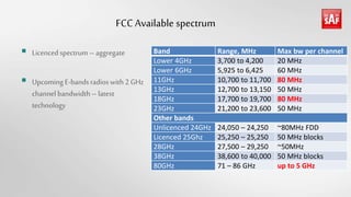
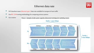
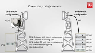
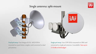
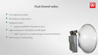
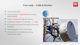
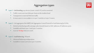
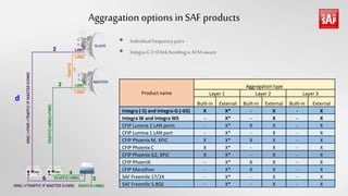
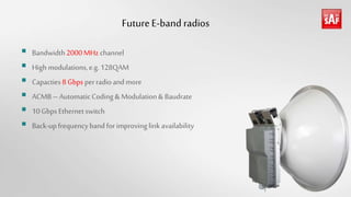
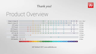

This document summarizes the capabilities of SAFTehnika's wireless backhaul solutions for achieving over 1Gbps capacities. It discusses available licensed spectrum bands with channel bandwidths up to 2000MHz that can support data rates over 8Gbps per radio. Mounting multiple radios to a single antenna is described as a way to save 5-10dB in link budget. A case study of a 1.7Gbps dual polarization link over 40 miles of water is provided. Layer 1-3 aggregation techniques are outlined including built-in and external options. Future E-band radios are projected to use 128QAM or higher with automatic coding and modulation capabilities.


