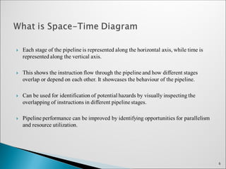
Pipelining isa technique of decomposing a sequential process into
suboperations, with each subprocess being executed in a special dedicated
segment that operates concurrently with all other segments.
A pipeline can be visualized as a collection of processing segments through
which binary information flows.
Each segment performs partial processing dictated by the way the task is
partitioned.
The result obtained from the computation in each segment is transferred to the
next segment in the pipeline.
The final result is obtained after the data have passed through all the segments.
The name pipeline implies the flow of data analogous to an Industrial assembly
line.
2
3.
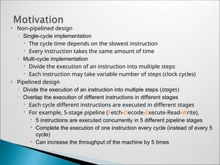
Non-pipelined design
◦Single-cycle implementation
The cycle time depends on the slowest instruction
Every instruction takes the same amount of time
◦ Multi-cycle implementation
Divide the execution of an instruction into multiple steps
Each instruction may take variable number of steps (clock cycles)
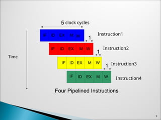
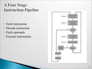
Pipelined design
◦ Divide the execution of an instruction into multiple steps (stages)
◦ Overlap the execution of different instructions in different stages
Each cycle different instructions are executed in different stages
For example, 5-stage pipeline (Fetch-Decode-Execute-Read-Write),
5 instructions are executed concurrently in 5 different pipeline stages
Complete the execution of one instruction every cycle (instead of every 5
cycle)
Can increase the throughput of the machine by 5 times
4.
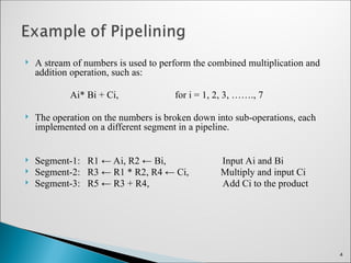
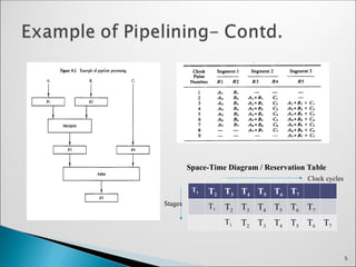
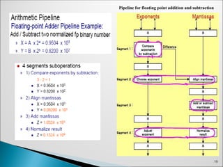
A streamof numbers is used to perform the combined multiplication and
addition operation, such as:
Ai* Bi + Ci, for i = 1, 2, 3, ……., 7
The operation on the numbers is broken down into sub-operations, each
implemented on a different segment in a pipeline.
Segment-1: R1 ← Ai, R2 ← Bi, Input Ai and Bi
Segment-2: R3 ← R1 * R2, R4 ← Ci, Multiply and input Ci
Segment-3: R5 ← R3 + R4, Add Ci to the product
4
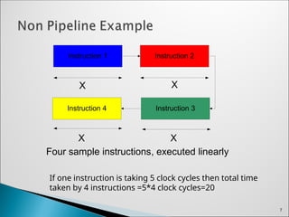
Instruction 1 Instruction2
Instruction 3
Instruction 4
X X
X
X
Four sample instructions, executed linearly
7
If one instruction is taking 5 clock cycles then total time
taken by 4 instructions =5*4 clock cycles=20
8.
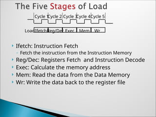
Ifetch: InstructionFetch
◦ Fetch the instruction from the Instruction Memory
Reg/Dec: Registers Fetch and Instruction Decode
Exec: Calculate the memory address
Mem: Read the data from the Data Memory
Wr: Write the data back to the register file
Cycle 1
Cycle 2 Cycle 3
Cycle 4Cycle 5
IfetchReg/Dec Exec Mem Wr
Load
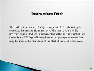
Instructions Fetch
Theinstruction Fetch (IF) stage is responsible for obtaining the
requested instruction from memory. The instruction and the
program counter (which is incremented to the next instruction) are
stored in the IF/ID pipeline register as temporary storage so that
may be used in the next stage at the start of the next clock cycle.
10
11.
Instruction Decode
TheInstruction Decode (ID) stage is responsible for decoding the
instruction and sending out the various control lines to the other
parts of the processor. The instruction is sent to the control unit
where it is decoded and the registers are fetched from the register
file.
11
12.
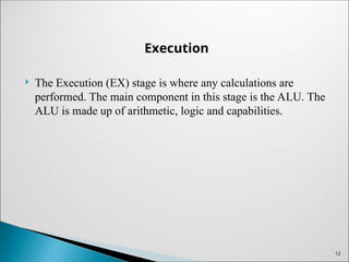
Execution
The Execution(EX) stage is where any calculations are
performed. The main component in this stage is the ALU. The
ALU is made up of arithmetic, logic and capabilities.
12
13.
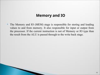
Memory and IO
The Memory and IO (MEM) stage is responsible for storing and loading
values to and from memory. It also responsible for input or output from
the processor. If the current instruction is not of Memory or IO type than
the result from the ALU is passed through to the write back stage.
13
14.
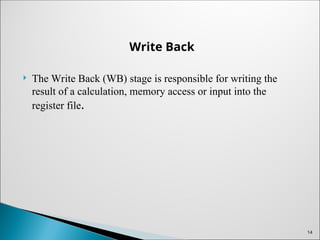
Write Back
TheWrite Back (WB) stage is responsible for writing the
result of a calculation, memory access or input into the
register file.
14
15.
An instructionpipeline reads consecutive instructions from
memory while previous instructions are being executed in
other segments.
Instructions are executed in FIFO order.
Each phase may require one or more clock cycles to execute
depending on the instruction type and processor/ memory
architecture used.
15
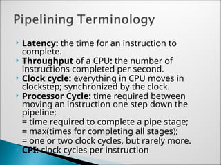
Latency: thetime for an instruction to
complete.
Throughput of a CPU: the number of
instructions completed per second.
Clock cycle: everything in CPU moves in
clockstep; synchronized by the clock.
Processor Cycle: time required between
moving an instruction one step down the
pipeline;
= time required to complete a pipe stage;
= max(times for completing all stages);
= one or two clock cycles, but rarely more.
CPI: clock cycles per instruction
21.
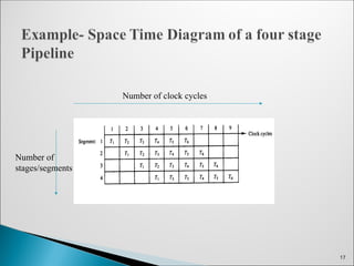
Once thepipe is filled it will output one result per clock period independent
of the number of stages in the pipe.
Ideally a linear pipeline with k stages can process n tasks in
T pipeline = (k+ n-1) * Tp
In a nonpipelined system the same number of tasks take,
Tnon-pipelined = n*k*Tp
21
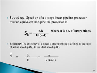
The pipelinethroughput H is defined as the number of tasks
performed per unit time.
n Efficiency
[ k+(n-1)] τ Clock period
23
Editor's Notes
#8 As shown here, each of these five steps will take one clock cycle to complete.
And in pipeline terminology, each step is referred to as one stage of the pipeline.
+1 = 8 min. (X:48)
#20 Here are some frequently used definitions about pipelining.
Latency is measured by the time for an instruction to complete.
Throughput is measured by the number of instructions a CPU can complete per second.
Clock cycle is the time duration of one lockstep of CPU.
Processor cycle is the time required to complete a pipe stage. As we observed from the laundry example, the slowest stage determines the length of a processor cycle. It usually spans one or two clock cycles.
CPI represents the number of clock cycles an instruction takes.


![ The pipeline throughput H is defined as the number of tasks
performed per unit time.
n Efficiency
[ k+(n-1)] τ Clock period
23](https://image.slidesharecdn.com/pipelining-250421190256-95c96ee5/85/Pipelining-_-23-320.jpg)