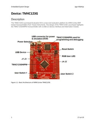
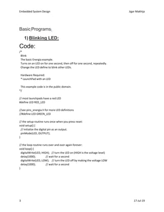
1. Embedded System Design Jigar Makhija
1 17-Jul-19
Device: TM4C123G
Description
The TM4C123G Launchpad Evaluation Kit is a low-cost evaluation platform for ARM Cortex-M4F
based microcontrollers from Texas Instruments. The design of the TM4C123G Launchpad highlights
the TM4C123GH6PM microcontroller with a USB 2.0 device interface and hibernation module.
Figure 1.1- Basic Architecture of ARM Cortex TM4C123G
2. Embedded System Design Jigar Makhija
2 17-Jul-19
Figure 1.2: Detail Pin Diagram for TM4C123G
Configuration & Tools:
Energia IDE: https://energia.nu/download/
Note: Install Appropriate Drivers
Reference : https://energia.nu/pinmaps/ek-tm4c123gxl/
3. Embedded System Design Jigar Makhija
3 17-Jul-19
Basic Programs:
1) Blinking LED:
Code:
/*
Blink
The basic Energia example.
Turns on an LED on for one second, then off for one second, repeatedly.
Change the LED define to blink other LEDs.
Hardware Required:
* LaunchPad with an LED
This example code is in the public domain.
*/
// most launchpads have a red LED
#define LED RED_LED
//see pins_energia.h for more LED definitions
//#define LED GREEN_LED
// the setup routine runs once when you press reset:
void setup() {
// initialize the digital pin as an output.
pinMode(LED, OUTPUT);
}
// the loop routine runs over and over again forever:
void loop() {
digitalWrite(LED, HIGH); // turn the LED on (HIGH is the voltage level)
delay(1000); // wait for a second
digitalWrite(LED, LOW); // turn the LED off by making the voltage LOW
delay(1000); // wait for a second
}
4. Embedded System Design Jigar Makhija
4 17-Jul-19
2) Digital Serial Read:
Code:
/*
DigitalReadSerial with on-board Pushbutton
Reads a digital input on pin 31, prints the result to the serial monitor
// digital pin 5 has a pushbutton attached to it. Give it a name:
int pushButton = 31;
// the setup routine runs once when you press reset:
void setup() {
// initialize serial communication at 9600 bits per second:
Serial.begin(9600); // msp430g2231 must use 4800
// make the on-board pushbutton's pin an input pullup:
pinMode(pushButton, INPUT_PULLUP);
}
// the loop routine runs over and over again forever:
void loop() {
5. Embedded System Design Jigar Makhija
5 17-Jul-19
// read the input pin:
int buttonState = digitalRead(pushButton);
// print out the state of the button:
Serial.println(buttonState);
delay(1); // delay in between reads for stability
}
3) Temperature Humidity:
Device Required: DHT11
Package need to be installed and imported:
Install:
- Adafruit Unified Sensor Library: https://github.com/adafruit/Adafruit_Sensor
- DHT Sensor Library: https://github.com/adafruit/DHT-sensor-library
Importing Library: Sketch->Include Library->Add. Zip Library
6. Embedded System Design Jigar Makhija
6 17-Jul-19
Code:
// DHT Temperature & Humidity Sensor
// Unified Sensor Library Example
// - Adafruit Unified Sensor Library: https://github.com/adafruit/Adafruit_Sensor
// - DHT Sensor Library: https://github.com/adafruit/DHT-sensor-library
#include <Adafruit_Sensor.h>
#include <DHT.h>
#include <DHT_U.h>
#define DHTPIN 05 // Pin which is connected to the DHT sensor.
// Uncomment the type of sensor in use:
#define DHTTYPE DHT11 // DHT 11
// See guide for details on sensor wiring and usage:
// https://learn.adafruit.com/dht/overview
DHT_Unified dht(DHTPIN, DHTTYPE);
uint32_t delayMS;
void setup() {
Serial.begin(9600);
// Initialize device.
dht.begin();
Serial.println("DHTxx Unified Sensor Example");
// Print temperature sensor details.
sensor_t sensor;
dht.temperature().getSensor(&sensor);
Serial.println("------------------------------------");
Serial.println("Temperature");
Serial.print ("Sensor: "); Serial.println(sensor.name);
Serial.print ("Driver Ver: "); Serial.println(sensor.version);
Serial.print ("Unique ID: "); Serial.println(sensor.sensor_id);
Serial.print ("Max Value: "); Serial.print(sensor.max_value); Serial.println(" *C");
Serial.print ("Min Value: "); Serial.print(sensor.min_value); Serial.println(" *C");
Serial.print ("Resolution: "); Serial.print(sensor.resolution); Serial.println(" *C");
Serial.println("------------------------------------");
// Print humidity sensor details.
dht.humidity().getSensor(&sensor);
Serial.println("------------------------------------");
7. Embedded System Design Jigar Makhija
7 17-Jul-19
Serial.println("Humidity");
Serial.print ("Sensor: "); Serial.println(sensor.name);
Serial.print ("Driver Ver: "); Serial.println(sensor.version);
Serial.print ("Unique ID: "); Serial.println(sensor.sensor_id);
Serial.print ("Max Value: "); Serial.print(sensor.max_value); Serial.println("%");
Serial.print ("Min Value: "); Serial.print(sensor.min_value); Serial.println("%");
Serial.print ("Resolution: "); Serial.print(sensor.resolution); Serial.println("%");
Serial.println("------------------------------------");
// Set delay between sensor readings based on sensor details.
delayMS = sensor.min_delay / 1000;
}
void loop() {
delay(delayMS);
sensors_event_t event;
dht.temperature().getEvent(&event); /* Read temperature value */
if (isnan(event.temperature)) { /* If temperature value is not a number */
Serial.println("Error reading temperature!");
}
else {
Serial.print("Temperature : ");
Serial.print(event.temperature);
Serial.println(" *C");
}
dht.humidity().getEvent(&event); /* Read humidity value */
if (isnan(event.relative_humidity)) { /* If humidity value is not a number */
Serial.println("Error reading humidity!");
}
else {
Serial.print("Humidity : ");
Serial.print(event.relative_humidity);
Serial.println("%");
}
}
8. Embedded System Design Jigar Makhija
8 17-Jul-19
4) LED Blink through Bluetooth Terminal from Mobile
Hardware: HC-05
Mobile App: Any HC-05 Terminal Application from Play store
Code:
#define LED RED_LED
void setup() {
Serial1.begin(9600); /* Define baud rate for serial communication */
pinMode(LED, OUTPUT);
}
void loop() {
if (Serial1.available()) /* If data is available on serial port */
{
char data_received;
data_received = Serial1.read(); /* Data received from bluetooth */
if (data_received == '1')
{
digitalWrite(LED, HIGH);
Serial1.write("nLED turned ON");
9. Embedded System Design Jigar Makhija
9 17-Jul-19
}
else if (data_received == '2')
{
digitalWrite(LED, LOW);
Serial1.write("nLED turned OFF");
}
else
{
Serial1.write("nSelect either 1 or 2");
}
}
}
5) A6 GSM Module for Calling and Messaging.
Hardware: A6 GSM/GPRS
Resources: 2G or 3G Sim Card
10. Embedded System Design Jigar Makhija
10 17-Jul-19
Code – Testing AT Commands:
void setup() {
//Begin serial communication (Serial Monitor)
Serial.begin(9600);
//Begin serial communication with Energia and A6
Serial1.begin(9600);
Serial.println("Initializing...");
delay(1000);
Serial1.println("AT"); //Once the handshake test is successful, it will back to OK
updateSerial();
Serial1.println("AT+CSQ"); //Signal quality test, value range is 0-31 , 31 is the best
updateSerial();
Serial1.println("AT+CCID"); //Read SIM information to confirm whether the SIM is plugged
updateSerial();
Serial1.println("AT+CREG?"); //Check whether it has registered in the network
updateSerial();
}
void loop() {
updateSerial();
}
void updateSerial()
{
delay(500);
while (Serial.available())
{
Serial1.write(Serial.read());//Forward what Serial received to Software Serial Port
}
while(Serial1.available())
{
Serial.write(Serial1.read());
//Forward what Software Serial received to Serial Port
}
}
11. Embedded System Design Jigar Makhija
11 17-Jul-19
AT – It is the most basic AT command. It also initializes Auto-baud’er. If it works
you should see the AT characters echo and then OK, telling you it’s OK and it’s
understanding you correctly! You can then send some commands to query the
module and get information about it such as
AT+CSQ – Check the ‘signal strength’ – the first # is dB strength, it should be
higher than around 5. Higher is better. Of course, it depends on your antenna
and location!
AT+CCID – get the SIM card number – this tests that the SIM card is found OK
and you can verify the number is written on the card.
AT+CREG? Check that you’re registered on the network. The second # should
be 1 or 5. 1 indicates you are registered to home network and 5 indicates
roaming network. Other than these two numbers indicate you are not registered
to any network.
ATI – Get the module name and revision
AT+COPS? – Check which network you are connected to, in this case 40466
(BSNL)
AT+COPS=? – Return the list of operators present in the network.
12. Embedded System Design Jigar Makhija
12 17-Jul-19
Code – Sending SMS/ Reading SMS
void setup() {
//Begin serial communication with Energia and Energia IDE (Serial Monitor)
Serial.begin(9600);
//Begin serial communication with Energia and A6
Serial1.begin(9600);
Serial.println("Initializing...");
delay(1000);
Serial1.println("AT"); //Once the handshake test is successful, it will back to OK
updateSerial();
Serial1.println("AT+CMGF=1"); // Configuring TEXT mode
updateSerial();
//Module to Send Message
/*Serial1.println("AT+CMGS="+91xxXXXXXXXX"");//change ZZ with country code and xxxxxxxxxxx
with phone number to sms
updateSerial();
Serial1.print("Last Minute TEST | Successful"); //text content
*/
//Code to Read Current New Messages
Serial1.println("AT+CNMI=1,2,0,0,0"); // Decides how newly arrived SMS messages should be handled
13. Embedded System Design Jigar Makhija
13 17-Jul-19
updateSerial();
// Serial1.write(26); //Remove Comment for Serial write to Send Message
}
void loop() {
updateSerial();
}
void updateSerial()
{
delay(500);
while (Serial.available())
{
Serial1.write(Serial.read());//Forward what Serial received to Software Serial Port
}
while(Serial1.available())
{
Serial.write(Serial1.read());//Forward what Software Serial received to Serial Port
}
}
Sending:
The sketch is almost same as earlier except below code snippet. Once the
connection is established, we send below AT commands:
AT+CMGF=1 – Selects SMS message format as text. Default format
is Protocol Data Unit (PDU)
AT+CMGS=+ZZxxxxxxxxxx – Sends SMS to the phone number specified. Once
we send a message.
Receiving:
The sketch is similar as earlier except below code snippet. Once the connection
is established, we send below AT commands:
14. Embedded System Design Jigar Makhija
14 17-Jul-19
AT+CMGF=1 – Selects SMS message format as text. Default format
is Protocol Data Unit (PDU)
AT+CNMI=1,2,0,0,0 – specifies how newly arrived SMS messages should be
handled. This way you can tell the A6 module either to forward newly arrived
SMS messages directly to the PC, or to save them in message storage and then
notify the PC about their locations in message storage.
Its response starts with +CMT: All the fields in the response are comma-
separated with first field being phone number. The second field is the name of
person sending SMS. Third field is a timestamp while forth field is the actual
message.
Sending
Receiving
15. Embedded System Design Jigar Makhija
15 17-Jul-19
Code – Making Call/ Receiving Call
void setup() {
//Begin serial communication with Energia and Energia IDE (Serial Monitor)
Serial.begin(9600);
//Begin serial communication with Energia and A6
Serial1.begin(9600);
Serial.println("Initializing...");
delay(1000);
Serial1.println("AT"); //Once the handshake test is successful, it will back to OK
updateSerial();
//Highlighted Code to Make a Call or Remove Highlighted code to Receive the calls
Serial1.println("ATD+91XXXXXXXXXX"); // change ZZ with country code and xxxxxxxxxxx with phone
number to dial
updateSerial();
delay(20000); // wait for 20 seconds...
Serial1.println("ATH"); //hang up
updateSerial();
}
void loop() {
updateSerial();
}
void updateSerial()
{
delay(500);
while (Serial.available())
{
Serial1.write(Serial.read());//Forward what Serial received to Software Serial Port
}
while(Serial1.available())
{
Serial.write(Serial1.read());//Forward what Software Serial received to Serial Port
}
}
ATD+ZZxxxxxxxxxx; – Dials a specified number.
16. Embedded System Design Jigar Makhija
16 17-Jul-19
ATH – Hangs up the call
Sending Calls:
Receiving Call: