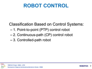
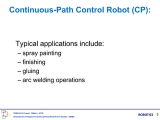
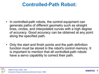
1) Robots are classified based on their control systems into point-to-point robots, continuous-path robots, and controlled-path robots.
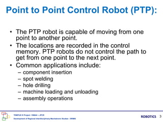
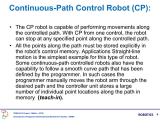
2) Point-to-point robots move between programmed points, continuous-path robots can stop at any point along a programmed path, and controlled-path robots can generate complex paths with a high degree of accuracy.
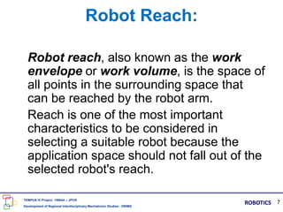
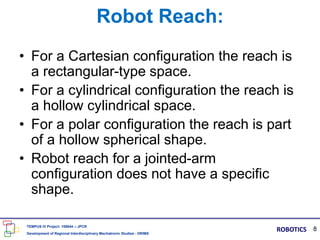
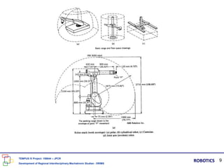
3) Robot reach refers to the space of points the robot arm can access and is an important factor to consider when selecting a robot for an application.


![[Deck] What's New in Spark-Iceberg Integration via DSV2.pptx](https://cdn.slidesharecdn.com/ss_thumbnails/deckwhatsnewinspark-icebergintegrationviadsv2-260210005337-25955b12-thumbnail.jpg?width=640&height=640&fit=bounds)


