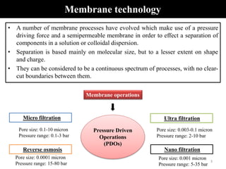
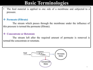
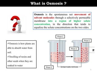
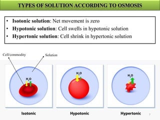
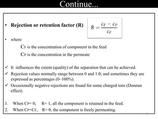
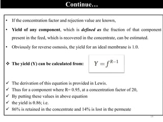
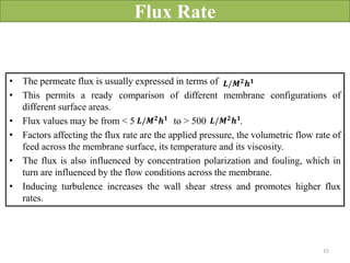
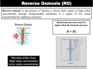
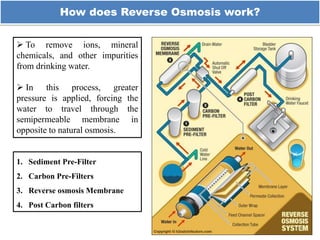
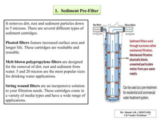
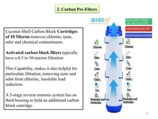
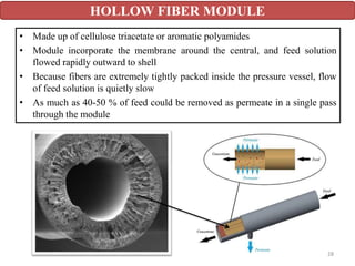
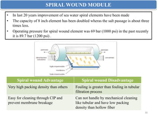
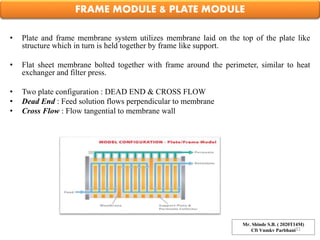
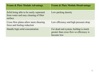
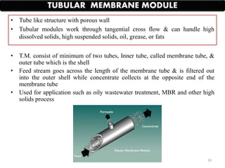
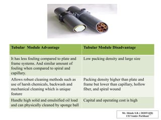
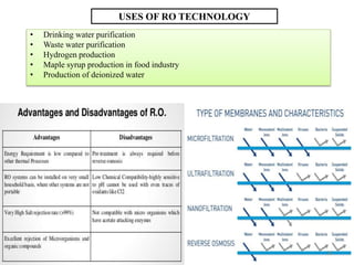
SlideShare a Scribd company logo
REVERSE OSMOSIS & NANOFILTRATION
(Advanced Food Engineering FST-603)
COLLEGE OF FOOD TECHNOLOGY
V.N.M.K.V. PARBHANI
Submitted By Course Guide
Mr. S.B. Shinde
Reg. No: 2020T14M
M.Tech Food technology
College of Food Technology
VNMKV Parbhani 431402
Dr. R.B. Kshirsagar
Dept. Food Engineering
College of Food Technology
VNMKV Parbhani 431402
1
Siddheshwarshinde@hotmail.com
• What is Membrane technology
• Basic terminologies
• What exactly happens in osmosis
• Osmotic pressure & Laws
• Reverse osmosis phenomenon
• Theoretical background of RO
• Filters and modules
• Applications of RO technology
• Nanofiltration
• Transport theories of NF
• Applications of NF
• References
OUTPUT
Mr. Shinde S.B. ( 2020T14M)
Cft Vnmkv Parbhani
2
Membrane operations
Micro filtration Ultra filtration
Nano filtration
Reverse osmosis
Pore size: 0.1-10 micron
Pressure range: 0.1-3 bar
Pore size: 0.003-0.1 micron
Pressure range: 2-10 bar
Pore size: 0.0001 micron
Pressure range: 15-80 bar
Pore size: 0.001 micron
Pressure range: 5-35 bar
Pressure Driven
Operations
(PDOs)
• A number of membrane processes have evolved which make use of a pressure
driving force and a semipermeable membrane in order to effect a separation of
components in a solution or colloidal dispersion.
• Separation is based mainly on molecular size, but to a lesser extent on shape
and charge.
• They can be considered to be a continuous spectrum of processes, with no clear-
cut boundaries between them.
Membrane technology
3
Basic Terminologies
• The feed material is applied to one side of a membrane and subjected to a
pressure.
 Permeate (Filtrate)
The stream which passes through the membrane under the influence of
this pressure is termed the permeate (filtrate).
 Concentrate or Retentate
The stream left after the required amount of permeate is removed is
termed the concentrate or retentate.
4
What is Osmosis ?
Osmosis is the spontaneous net movement of
solvent molecules through a selectively permeable
membrane into a region of higher solute
concentration, in the direction that tends to
equalize the solute concentrations on the two sides.
Osmosis is how plants are
able to absorb water from
soil.
Swelling of resins and
other seeds when they are
soaked in water
Phase 1
Phase 2
Phase 1
Phase 2
π
5
WHAT
EXACTLY
HAPPENS
Mango shrinken in salt solution : Osmosis
Dates swells after soaked in water
Plasmolysis
6
• Isotonic solution: Net movement is zero
• Hypotonic solution: Cell swells in hypotonic solution
• Hypertonic solution: Cell shrink in hypertonic solution
Solution
Cell/commodity
7
What is Osmotic Pressure?
π = iCRT
Where,
π is the osmotic pressure
i is the van’t Hoff factor
C is the molar concentration of the solute in the solution
R is the universal gas constant
T is the temperature
If sufficient pressure is applied to the solution side of the semipermeable membrane, the
process of osmosis is halted. The minimum amount of pressure required to nullify the
process of osmosis is called osmotic pressure.
 Pressure to halt Osmosis Mechanism i.e. Movement of solvent to solution.
 Dependent on the concentration of solute particles in the solution
8
Laws of osmotic pressure
• Solute partical in dilute solution posses kinetic energy & moves random
directon in solution. Thus, they are similar to gas molecules
Van’t Hoff’s theory of osmotic pressure
Van’t Hoff’s Boyle’s Law of solution
• At constant temperature, osmotic pressure (π) of dilute solution is directly
proposnal to its molar concentration (C) or Inversely proposnal to volume
(V) of the solution
Expression:
Mr. Shinde S.B. ( 2020T14M)
Cft Vnmkv Parbhani9
Van’t Hoff’s Charle’s Law of solution
• When concentration remaining constant then osmotic pressure (π) of dilute
solution is directly proposnal to absolute temperature (T) of solution.
Expression:
Van’t Hoff’s Avagedro of solution
• At given temperature, equal volumes of the solutions having the same
osmotic pressure contain equal number of solute particles.
𝝅 ∝ 𝒏 10
Van’t Hoff’s general solution equation
• With the help of above three equation we can conclude general solution
equation.
From above all laws
π = iCRT
Osmotic pressure
11
Important processing parameters for all pressure
activated processes
 The concentration factor (f )
Where,
VF is the feed volume
VC is the final concentrate volume.
 As soon as the concentration factor exceeds 2.0, the volume of permeate
will exceed that of the concentrate.
 Concentration factors may be as low as 1.5 for some viscous materials and 5.0–
50 for some dilute protein solutions.
 Generally higher concentration factors are used for ultrafiltration than for RO:
 Over 50.0 can be achieved for UF treatment of cheese whey, compared to about
to 5 for RO treatment of cheese whey.
12
Continue...
• Rejection or retention factor (R)
• where
CF is the concentration of component in the feed
CP is the concentration in the permeate
 It influences the extent (quality) of the separation that can be achieved.
 Rejection values normally range between 0 and 1.0; and sometimes they are
expressed as percentages (0–100%).
 Occasionally negative rejections are found for some charged ions (Donnan
effect).
1. When CP= 0, R= 1, all the component is retained in the feed.
2. When CP=CF, R= 0, the component is freely permeating.
13
Continue…
• If the concentration factor and rejection value are known,
• Yield of any component, which is defined as the fraction of that component
present in the feed, which is recovered in the concentrate, can be estimated.
• Obviously for reverse osmosis, the yield for an ideal membrane is 1.0.
 The yield (Y) can be calculated from:
 The derivation of this equation is provided in Lewis.
 Thus for a component where R= 0.95, at a concentration factor of 20,
 By putting these values in above equation
 the yield is 0.86; i.e.
 86% is retained in the concentrate and 14% is lost in the permeate
14
Flux Rate
• The permeate flux is usually expressed in terms of
• This permits a ready comparison of different membrane configurations of
different surface areas.
• Flux values may be from < 5 to > 500 .
• Factors affecting the flux rate are the applied pressure, the volumetric flow rate of
feed across the membrane surface, its temperature and its viscosity.
• The flux is also influenced by concentration polarization and fouling, which in
turn are influenced by the flow conditions across the membrane.
• Inducing turbulence increases the wall shear stress and promotes higher flux
rates.
𝑳/𝑴𝟐
𝒉𝟏
𝑳/𝑴𝟐𝒉𝟏 𝑳/𝑴𝟐𝒉𝟏
15
Reverse Osmosis (RO)
Reverse osmosis is the process of forcing a solvent from region of high solute
concentration through semipermeable membrane to a region of low solute
concentration by Applying a pressure.
16
Hydrostatic pressure must be
higher than the Osmotic pressure
P > Pi
Direction of flow from
High solute concentration
to low solute concentration
How does Reverse Osmosis work?
 To remove ions, mineral
chemicals, and other impurities
from drinking water.
 In this process, greater
pressure is applied, forcing the
water to travel through the
semipermeable membrane in
opposite to natural osmosis.
1. Sediment Pre-Filter
2. Carbon Pre-Filters
3. Reverse osmosis Membrane
4. Post Carbon filters
17
1. Sediment Pre-Filter
It removes dirt, rust and sediment particles down
to 5 microns. There are several different types of
sediment cartridges.
Pleated filters feature increased surface area and
longer life. These cartridges are washable and
reusable.
Melt blown polypropylene filters are designed
for the removal of dirt, rust and sediment from
water. 5 and 20 micron are the most popular sizes
for drinking water applications.
String wound filters are an inexpensive solution
to your filtration needs. These cartridges come in
a variety of media types and have a wide range of
applications.
Mr. Shinde S.B. ( 2020T14M)
Cft Vnmkv Parbhani 18
2. Carbon Pre-Filters
Coconut Shell Carbon Block Cartridges
of 10 Micron removes chlorine, taste,
odor and chemical contaminants.
Activated carbon block filters typically
have a 0.5 to 10 micron filtration
This Capability, makes it also helpful for
particulate filtration, removing taste and
odor from chlorine, insoluble lead
reduction.
A 5-stage reverse osmosis system has an
third housing to hold an additional carbon
block cartridge.
19
• TFC (Thin Film Composite) rejects or removes 95% of total dissolved
solids (TDS) down to 0.0001 micron
• Different membrane modules are manufactured for use of water
purification or desalination system also in fuel cells.
3. Reverse osmosis Membrane
4. Post carbon Filters
• Coconut shell Activated carbon is final polishing.
• It is just before you use that water
• Inline post filters typically clip onto top of reverse osmosis systems
membrane housing
• This post filters removes any chlorine or contaminants missed by the other
cartilage or membrane.
20
Theoretical background
 According to the solution-diffusion transport mechanism (Salt & Water
permeate reverse osmosis membranes)
 The water flux, Ji is linked to the pressure and concentration gradient
across the membrane by the equation
Where
p is the pressure difference across the membrane,
π is the osmotic pressure differential across the membrane
A is constant
 When the applied pressure is higher than the osmotic pressure ( p > π )
Water flows from the concentrated to dilute salt solution side of membrane
21
The salt flux J(j) across a reverse osmosis membrane is described by the equation
Where
B is salt permeability constant
Cjo & CJi are the salt concentrations on the feed and permeate side of the membrane
Concentration of salt in the permeate solution is usually much smaller than the
concentration in feed , so the above equation can be simplified to,
It follows from these two equations that, the water flux is proposnal to the applied
pressure but the salt flux is independent of pressure
Thus it means the membrane becomes more selective as pressure increases
22
• For the RO system to produce product water, a minimum pressure must be
applied to the membrane to overcome the natural Osmotic pressure of the water.
• This pressure depends on the type of ion present and their concentration in water
• Osmotic pressure doesn’t depend on the type of membrane
• Roughly, every 10 ppm of TDS contribute about 1 psi of osmotic pressure
• For instance, if the TDS of feed water is 2000 ppm, then the Osmotic Pressure for
this water is about 20 psi
• Generally, the applied pressure is at least twice the OP for the variable RO system
Table gives information about how the permeate quality and quantity for a
membrane may change as pressure is reduced
23
RO: Cellulosic membrane
• Cellulose acetate was the first high-performance reverse osmosis membrane
material discovered. (year 1894)
• The water & salt permeability of CA membrane is extremely sensitive to the
degree of acetylation of the polymer used to make the membrane.
• These membrane achieve 98-99 % sodium chloride rejection in seawater
desalination process
FTIR
SEM
XRD
TGA
ANTIBACTERIAL
CHEMICAL RESISTANCE
24
ADVANTAGES OF CELLULOSIC MEMBRANE
• Easy to make
• Mechanically tough
• Cellulose acetate has higher flux
• Resistance to free chlorine concentration
• Kept free of bacteria
• Suitable to feed water having biological loading
RO: Non Cellulosic polymer membrane
During in 1960s to 1970s
Good sea water salt rejection upto 99.5 % but fluxes are low 1-3 gal/ft2
High chlorine rejection ( able to withstand upto 10000 ppm h)
High flux ( especially for polysulfone and poly vinyl alcohol.
Mr. Shinde S.B. ( 2020T14M)
Cft Vnmkv Parbhani
25
RO: Interfacial Composite Membrane
Interfacial composite membrane are formed over porous support by in-situ
polycondensation of polyfunctional amines and acid chloride monomers at the interface
of solvent
Advantages
• High flux & High rejection RO due to interfacial polymerization
• Also be operated at 35 oc temperature
• Salt rejection 995 % and water flux of 30 gal/ft2 day at 800 psi
26
RO Modules: Membrane Configurations
Four Different Types of RO Modules Used In Desalination Process
TUBULAR MODULE
FRAME MODULE & PLATE MODULE
SPIRAL MODULE
HOLLOW FIBER MODULE
Mr. Shinde S.B. ( 2020T14M)
Cft Vnmkv Parbhani
27
• Made up of cellulose triacetate or aromatic polyamides
• Module incorporate the membrane around the central, and feed solution
flowed rapidly outward to shell
• Because fibers are extremely tightly packed inside the pressure vessel, flow
of feed solution is quietly slow
• As much as 40-50 % of feed could be removed as permeate in a single pass
through the module
HOLLOW FIBER MODULE
28
Hollow fiber Advantage Hollow fiber Disadvantage
With high packing density because of
small strand diameter
Irreversible fouling & fiber breakage
Can be back flushed from the permeate
side and air scoured
Break under high strain compared to other
method and high operating cost
Mr. Shinde S.B. ( 2020T14M)
Cft Vnmkv Parbhani
29
SPIRAL WOUND MODULE
• In last 20 years improvement of sea water spiral elements have been made
• The capacity of 8 inch element has been doubled wheras the salt passage is about three
times less.
• Operating pressure for spiral wound element was 69 bar (1000 psi) in the past recently
it is 89.7 bar (1200 psi) .
30
Spiral wound Advantage Spiral wound Disadvantage
Very high packing density than others Fouling is greater than fouling in tubular
filtration process
Easy for cleaning through CIP and
prevent membrane breakage
Can not handle by mechanical cleaning
like tubular and have low packing
density than hollow fiber
FRAME MODULE & PLATE MODULE
• Plate and frame membrane system utilizes membrane laid on the top of the plate like
structure which in turn is held together by frame like support.
• Flat sheet membrane bolted together with frame around the perimeter, similar to heat
exchanger and filter press.
• Two plate configuration : DEAD END & CROSS FLOW
• Dead End : Feed solution flows perpendicular to membrane
• Cross Flow : Flow tangential to membrane wall
Mr. Shinde S.B. ( 2020T14M)
Cft Vnmkv Parbhani31
Frame & Plate Module Advantage Frame & Plate Module Disadvantage
Solid being able to be easily separated
from water and easy cleaning of filter
surface
Low packing density
Cross flow plates allow more shearing
force and fouling reduction
Low efficiency and high presuure drop
Handle high solid concentration For dead end system, buildup is much
greater than cross flow so efficiency is
become less
32
• T.M. consist of minimum of two tubes, Inner tube, called membrane tube, &
outer tube which is the shell
• Feed stream goes across the length of the membrane tube & is filtered out
into the outer shell while concentrate collects at the opposite end of the
membrane tube
• Used for application such as oily wastewater treatment, MBR and other high
solids process
TUBULAR MEMBRANE MODULE
• Tube like structure with porous wall
• Tubular modules work through tangential cross flow & can handle high
dissolved solids, high suspended solids, oil, grease, or fats
33
Tubular Module Advantage Tubular Module Disadvantage
It has less fouling compared to plate and
frame systems. And similar amount of
fouling when compared to spiral and
capillary.
Low packing density and large size
Allows robust cleaning methods such as
use of harsh chemicals, backwash and
mechanical cleaning which is unique
feature
Packing density higher than plate and
frame but lower than capillary, hollow
fiber, and spiral wound
Handle high solid and emulsified oil load
and can physically cleaned by sponge ball
Capital and operating cost is high
Mr. Shinde S.B. ( 2020T14M)
Cft Vnmkv Parbhani
34
USES OF RO TECHNOLOGY
• Drinking water purification
• Waste water purification
• Hydrogen production
• Maple syrup production in food industry
• Production of deionized water
35
NANOFITRATION
36
• Realm between reverse osmosis and ultrafiltration.
• Hydraulic pressure is used to overcome the feed solution osmotic pressure,
and to induce diffusion of pure water, which we also called as permeate
through a semi permeable nanofiltration membrane
Rejects
dissolved
organics
insecticide
s and
pesticides
herbicid
es
Antibioti
cs
nitrates,
sugars
What is Retentate??
size range of 1 nm or 10 Angstroms.
• Nanofiltration may achieve moderate to low
removal of monovalent ions.
For example, sodium, potassium, chloride etc
37
• The features of nanofiltration membranes lie between those of non-porous
RO membrane and porous ultrafiltration membranes
• Commercial nanofiltration membranes possess a fixed charge developed by
dissociation of surface groups such as sulphurated or carboxylic acids.
NF Membrane allow ions
to be separated by a
combination of the size
and electrical effects of
UF and the ion interaction
mechanisms of RO
38
Properties of NF
PLATE AND
FRAME FORM
HOLLOW FIBER
FORMATS
CAPILLARY
SPIRAL WOUND,
TUBULAR
MEMBRANES
• NF can withstand very high or low pH environment.
• Membrane tends to have a slightly charged surface with a negative charge at a
neutral pH.
39
Transport theories or models are adapted to describe the
Nanofiltration transport
1. Sourirajan’s sorption surface capillary flow model
2. Solution diffusion model
Sourirajan’s sorption surface capillary flow theory
• sorption of water molecules in the membrane. And then the desorption of
multivalent ions by dielectric forces
• effective charge density, pore radius and ionic strength determine the
rejection of monovalent ions.
• For nanofiltration membranes the rejection of monovalent ions ranges
between 0% to 50%.
Mr. Shinde S.B. ( 2020T14M)
Cft Vnmkv Parbhani
40
Solution diffusion model
• Describes the membrane as a porous film into which both water and solute
ions dissolve.
• Solute moves in the membrane mainly under the concentration gradient
forces.
• Water transport is dependent on the hydraulic pressure gradient.
• Transport of the solute through the membrane depends on the hindered
diffusion as well as convection.
Transport mechanism of charged solute
• Three modes of transfer:
 Diffusion
 Convection
 Electromigration
41
Parameters That Affect The Performance Of A
Nanofiltration Membrane
• Pressure
• Temperature
• Cross-Flow velocity
• Solution PH
NF Advantages NF Disadvantages
Lower discharge volumes, lower retained
concentrations than RO for low value salts
Higher energy consumption than
ultrafiltration and microfiltration
Reduction in heavy metals Limited retention for salts and univalent
ions
Reduced to nitrates and sulphates Expensive than reverse osmosis
membranes
Reduction in colour, tannins and turbidity Membranes are sensitive to free chlorine.
Most of the time chlorine is present in
water and water streams 42
NF Application
• Desalination of food, dairy and beverage products or by-products.
• Partial desalination of whey, UF permeate or retentate as required.
Desalination of dyes and optical brighteners.
• Purification of spent clean in place chemicals, CIP chemicals.
• Colour reduction or manipulation of food products.
• Concentration of food, dairy and beverage products or by-products.
• Fermentation byproduct concentration.
Mr. Shinde S.B. ( 2020T14M)
Cft Vnmkv Parbhani
43
REFRENCES
• Food Processing Handbook James G. Brennan
• M.H. Moulder, Basic techniques in membrane technology
• Https://www.Safewater.Org/fact-sheets1/2017/1/23/ultrafiltrationnanoandro
• B.K. Datta Mass transfer and seperation process 2007
• K. Nath Membrane seperation processes PHI 2008
• M.cheryan ultrafiltration and microfiltration hand book
• Membrane Technology Prof. Kaustubha Mohanty Department of
Chemical Engineering Indian Institute of Technology, Guwahati
Mr. Shinde S.B. ( 2020T14M)
Cft Vnmkv Parbhani 44
Mr. Shinde S.B. ( 2020T14M)
M. Tech food technology
Cft Vnmkv Parbhani 45

More Related Content

What's hot

Reverse osmosis
Reverse osmosisReverse osmosis
Reverse osmosis
Nikhil Reddy
 
Sedimentation tanks in water treatment
Sedimentation tanks in water treatmentSedimentation tanks in water treatment
Sedimentation tanks in water treatment
Ramodh Jayawardena
 
Reverse osmosis for water purification
Reverse osmosis for water purificationReverse osmosis for water purification
Reverse osmosis for water purification
Neslihan Yagmur
 
Membrane technology
Membrane technologyMembrane technology
Membrane technology
Paulus Hartanto
 
Reverse Osmosis
Reverse Osmosis Reverse Osmosis
Reverse Osmosis
Piyush Hatwalne
 
Biological Nutrient Removal
Biological Nutrient RemovalBiological Nutrient Removal
Biological Nutrient Removal
krishnacp
 
WATER & WASTE WATER ENGINEERING - water treatment process & units
WATER & WASTE WATER ENGINEERING -  water treatment process & unitsWATER & WASTE WATER ENGINEERING -  water treatment process & units
WATER & WASTE WATER ENGINEERING - water treatment process & units
Eddy Ankit Gangani
 
Development Of Ro Membrane &amp; Its Characterization
Development Of Ro Membrane &amp; Its CharacterizationDevelopment Of Ro Membrane &amp; Its Characterization
Development Of Ro Membrane &amp; Its Characterization
Zed Siddy
 
Membrane separation process
Membrane separation processMembrane separation process
Membrane separation process
KrishnaKantNayak2
 
Filtration in water treatment
Filtration in water treatmentFiltration in water treatment
Filtration in water treatment
Dayananda Sreekanta
 
Presentation
PresentationPresentation
Presentation
Mohamad Kanakri
 
Membrane Separation Processes
Membrane Separation ProcessesMembrane Separation Processes
Membrane Separation Processes
Nitish Gupta
 
Water recycling & membrane technology
Water recycling & membrane technologyWater recycling & membrane technology
Water recycling & membrane technology
kanhaiya kumawat
 
Reverse Osmosis Technology
Reverse Osmosis TechnologyReverse Osmosis Technology
Reverse Osmosis Technology
Awais Chaudhary
 
Water Quality Control and Treatment Water Treatment
Water Quality Control and Treatment Water Treatment Water Quality Control and Treatment Water Treatment
Water Quality Control and Treatment Water Treatment
Bakr Younis /Al-Azhar University – Gaza
 
Wastewater engineering info
Wastewater engineering infoWastewater engineering info
Wastewater engineering info
TadviDevarshi
 
mechanism of filtration, surface and depth filters
mechanism of filtration, surface and depth filtersmechanism of filtration, surface and depth filters
mechanism of filtration, surface and depth filters
saqib_sulman
 
06 Treatment of water -Filtration and Water Softening
06 Treatment of water -Filtration and Water Softening06 Treatment of water -Filtration and Water Softening
06 Treatment of water -Filtration and Water Softening
akashpadole
 
Water treatment process by RO UF
Water treatment process by RO UFWater treatment process by RO UF
Water treatment process by RO UF
ceutics1315
 
Lecture 17- Advanced Membrane Separation Processes.pptx
Lecture 17- Advanced Membrane Separation Processes.pptxLecture 17- Advanced Membrane Separation Processes.pptx
Lecture 17- Advanced Membrane Separation Processes.pptx
atee9t
 

What's hot (20)

Reverse osmosis
Reverse osmosisReverse osmosis
Reverse osmosis
 
Sedimentation tanks in water treatment
Sedimentation tanks in water treatmentSedimentation tanks in water treatment
Sedimentation tanks in water treatment
 
Reverse osmosis for water purification
Reverse osmosis for water purificationReverse osmosis for water purification
Reverse osmosis for water purification
 
Membrane technology
Membrane technologyMembrane technology
Membrane technology
 
Reverse Osmosis
Reverse Osmosis Reverse Osmosis
Reverse Osmosis
 
Biological Nutrient Removal
Biological Nutrient RemovalBiological Nutrient Removal
Biological Nutrient Removal
 
WATER & WASTE WATER ENGINEERING - water treatment process & units
WATER & WASTE WATER ENGINEERING -  water treatment process & unitsWATER & WASTE WATER ENGINEERING -  water treatment process & units
WATER & WASTE WATER ENGINEERING - water treatment process & units
 
Development Of Ro Membrane &amp; Its Characterization
Development Of Ro Membrane &amp; Its CharacterizationDevelopment Of Ro Membrane &amp; Its Characterization
Development Of Ro Membrane &amp; Its Characterization
 
Membrane separation process
Membrane separation processMembrane separation process
Membrane separation process
 
Filtration in water treatment
Filtration in water treatmentFiltration in water treatment
Filtration in water treatment
 
Presentation
PresentationPresentation
Presentation
 
Membrane Separation Processes
Membrane Separation ProcessesMembrane Separation Processes
Membrane Separation Processes
 
Water recycling & membrane technology
Water recycling & membrane technologyWater recycling & membrane technology
Water recycling & membrane technology
 
Reverse Osmosis Technology
Reverse Osmosis TechnologyReverse Osmosis Technology
Reverse Osmosis Technology
 
Water Quality Control and Treatment Water Treatment
Water Quality Control and Treatment Water Treatment Water Quality Control and Treatment Water Treatment
Water Quality Control and Treatment Water Treatment
 
Wastewater engineering info
Wastewater engineering infoWastewater engineering info
Wastewater engineering info
 
mechanism of filtration, surface and depth filters
mechanism of filtration, surface and depth filtersmechanism of filtration, surface and depth filters
mechanism of filtration, surface and depth filters
 
06 Treatment of water -Filtration and Water Softening
06 Treatment of water -Filtration and Water Softening06 Treatment of water -Filtration and Water Softening
06 Treatment of water -Filtration and Water Softening
 
Water treatment process by RO UF
Water treatment process by RO UFWater treatment process by RO UF
Water treatment process by RO UF
 
Lecture 17- Advanced Membrane Separation Processes.pptx
Lecture 17- Advanced Membrane Separation Processes.pptxLecture 17- Advanced Membrane Separation Processes.pptx
Lecture 17- Advanced Membrane Separation Processes.pptx
 

Similar to Reverse Osmosis & Nano Filtration

ReverseOsmosisLabReport
ReverseOsmosisLabReportReverseOsmosisLabReport
ReverseOsmosisLabReport
Janet Mok
 
Membrane filtration technology in food engg.
Membrane filtration technology in food engg.Membrane filtration technology in food engg.
Membrane filtration technology in food engg.
Maya Sharma
 
Osmotic drug delivery system
Osmotic drug delivery system Osmotic drug delivery system
Osmotic drug delivery system
vineet gupta
 
Osmotic drug delivery system
Osmotic drug delivery systemOsmotic drug delivery system
Osmotic drug delivery system
Dr. Shreeraj Shah
 
Unit process
Unit processUnit process
RO
RORO
Osmotic Drug Delivery System
Osmotic Drug Delivery SystemOsmotic Drug Delivery System
Osmotic Drug Delivery System
Dr Gajanan Sanap
 
Osmotic drug delivery-converted
Osmotic drug delivery-convertedOsmotic drug delivery-converted
Osmotic drug delivery-converted
DHRUV GANDHI
 
Osmotic Drug Delivery System and basic components of Osmotic system
Osmotic Drug Delivery System  and  basic components of Osmotic systemOsmotic Drug Delivery System  and  basic components of Osmotic system
Osmotic Drug Delivery System and basic components of Osmotic system
DhanashreeDavare
 
Group presentation on Reverse Osmosis and Nanofiltration
Group presentation on Reverse Osmosis and NanofiltrationGroup presentation on Reverse Osmosis and Nanofiltration
Group presentation on Reverse Osmosis and Nanofiltration
zaman_866
 
Hplc doc
Hplc docHplc doc
Hplc doc
saikumar1558
 
Sttp ppt msp_overview_09-10-2009_zvpm
Sttp ppt msp_overview_09-10-2009_zvpmSttp ppt msp_overview_09-10-2009_zvpm
Sttp ppt msp_overview_09-10-2009_zvpm
Arvind Kumar
 
Upload2 chemistry reverse osmisis
Upload2 chemistry reverse osmisisUpload2 chemistry reverse osmisis
Upload2 chemistry reverse osmisis
Vellore Institute of Technology
 
13 membranes
13 membranes13 membranes
13 membranes
safwan patel
 
Temperature modeling.pdf
Temperature modeling.pdfTemperature modeling.pdf
Temperature modeling.pdf
abreham25
 
Osmotic systems
Osmotic systemsOsmotic systems
Osmotic systems
Ravish Yadav
 
CE 498 Report
CE 498 ReportCE 498 Report
CE 498 Report
Ananthan Balachandran
 
6. Short Reverse Phase-HPLC(2).pdf
6. Short Reverse Phase-HPLC(2).pdf6. Short Reverse Phase-HPLC(2).pdf
6. Short Reverse Phase-HPLC(2).pdf
rimshaijaz4709
 
Forward osmosis
Forward osmosisForward osmosis
Forward osmosis
NISHANK WAGHMARE
 
Dissolution
DissolutionDissolution
Dissolution
Shreeshail Tumbagi
 

Similar to Reverse Osmosis & Nano Filtration (20)

ReverseOsmosisLabReport
ReverseOsmosisLabReportReverseOsmosisLabReport
ReverseOsmosisLabReport
 
Membrane filtration technology in food engg.
Membrane filtration technology in food engg.Membrane filtration technology in food engg.
Membrane filtration technology in food engg.
 
Osmotic drug delivery system
Osmotic drug delivery system Osmotic drug delivery system
Osmotic drug delivery system
 
Osmotic drug delivery system
Osmotic drug delivery systemOsmotic drug delivery system
Osmotic drug delivery system
 
Unit process
Unit processUnit process
Unit process
 
RO
RORO
RO
 
Osmotic Drug Delivery System
Osmotic Drug Delivery SystemOsmotic Drug Delivery System
Osmotic Drug Delivery System
 
Osmotic drug delivery-converted
Osmotic drug delivery-convertedOsmotic drug delivery-converted
Osmotic drug delivery-converted
 
Osmotic Drug Delivery System and basic components of Osmotic system
Osmotic Drug Delivery System  and  basic components of Osmotic systemOsmotic Drug Delivery System  and  basic components of Osmotic system
Osmotic Drug Delivery System and basic components of Osmotic system
 
Group presentation on Reverse Osmosis and Nanofiltration
Group presentation on Reverse Osmosis and NanofiltrationGroup presentation on Reverse Osmosis and Nanofiltration
Group presentation on Reverse Osmosis and Nanofiltration
 
Hplc doc
Hplc docHplc doc
Hplc doc
 
Sttp ppt msp_overview_09-10-2009_zvpm
Sttp ppt msp_overview_09-10-2009_zvpmSttp ppt msp_overview_09-10-2009_zvpm
Sttp ppt msp_overview_09-10-2009_zvpm
 
Upload2 chemistry reverse osmisis
Upload2 chemistry reverse osmisisUpload2 chemistry reverse osmisis
Upload2 chemistry reverse osmisis
 
13 membranes
13 membranes13 membranes
13 membranes
 
Temperature modeling.pdf
Temperature modeling.pdfTemperature modeling.pdf
Temperature modeling.pdf
 
Osmotic systems
Osmotic systemsOsmotic systems
Osmotic systems
 
CE 498 Report
CE 498 ReportCE 498 Report
CE 498 Report
 
6. Short Reverse Phase-HPLC(2).pdf
6. Short Reverse Phase-HPLC(2).pdf6. Short Reverse Phase-HPLC(2).pdf
6. Short Reverse Phase-HPLC(2).pdf
 
Forward osmosis
Forward osmosisForward osmosis
Forward osmosis
 
Dissolution
DissolutionDissolution
Dissolution
 

Recently uploaded

Technical Drawings introduction to drawing of prisms
Technical Drawings introduction to drawing of prismsTechnical Drawings introduction to drawing of prisms
Technical Drawings introduction to drawing of prisms
heavyhaig
 
6th International Conference on Machine Learning & Applications (CMLA 2024)
6th International Conference on Machine Learning & Applications (CMLA 2024)6th International Conference on Machine Learning & Applications (CMLA 2024)
6th International Conference on Machine Learning & Applications (CMLA 2024)
ClaraZara1
 
ML Based Model for NIDS MSc Updated Presentation.v2.pptx
ML Based Model for NIDS MSc Updated Presentation.v2.pptxML Based Model for NIDS MSc Updated Presentation.v2.pptx
ML Based Model for NIDS MSc Updated Presentation.v2.pptx
JamalHussainArman
 
Advanced control scheme of doubly fed induction generator for wind turbine us...
Advanced control scheme of doubly fed induction generator for wind turbine us...Advanced control scheme of doubly fed induction generator for wind turbine us...
Advanced control scheme of doubly fed induction generator for wind turbine us...
IJECEIAES
 
2. Operations Strategy in a Global Environment.ppt
2. Operations Strategy in a Global Environment.ppt2. Operations Strategy in a Global Environment.ppt
2. Operations Strategy in a Global Environment.ppt
PuktoonEngr
 
CSM Cloud Service Management Presentarion
CSM Cloud Service Management PresentarionCSM Cloud Service Management Presentarion
CSM Cloud Service Management Presentarion
rpskprasana
 
132/33KV substation case study Presentation
132/33KV substation case study Presentation132/33KV substation case study Presentation
132/33KV substation case study Presentation
kandramariana6
 
Swimming pool mechanical components design.pptx
Swimming pool  mechanical components design.pptxSwimming pool  mechanical components design.pptx
Swimming pool mechanical components design.pptx
yokeleetan1
 
KuberTENes Birthday Bash Guadalajara - K8sGPT first impressions
KuberTENes Birthday Bash Guadalajara - K8sGPT first impressionsKuberTENes Birthday Bash Guadalajara - K8sGPT first impressions
KuberTENes Birthday Bash Guadalajara - K8sGPT first impressions
Victor Morales
 
Manufacturing Process of molasses based distillery ppt.pptx
Manufacturing Process of molasses based distillery ppt.pptxManufacturing Process of molasses based distillery ppt.pptx
Manufacturing Process of molasses based distillery ppt.pptx
Madan Karki
 
RAT: Retrieval Augmented Thoughts Elicit Context-Aware Reasoning in Long-Hori...
RAT: Retrieval Augmented Thoughts Elicit Context-Aware Reasoning in Long-Hori...RAT: Retrieval Augmented Thoughts Elicit Context-Aware Reasoning in Long-Hori...
RAT: Retrieval Augmented Thoughts Elicit Context-Aware Reasoning in Long-Hori...
thanhdowork
 
International Conference on NLP, Artificial Intelligence, Machine Learning an...
International Conference on NLP, Artificial Intelligence, Machine Learning an...International Conference on NLP, Artificial Intelligence, Machine Learning an...
International Conference on NLP, Artificial Intelligence, Machine Learning an...
gerogepatton
 
Iron and Steel Technology Roadmap - Towards more sustainable steelmaking.pdf
Iron and Steel Technology Roadmap - Towards more sustainable steelmaking.pdfIron and Steel Technology Roadmap - Towards more sustainable steelmaking.pdf
Iron and Steel Technology Roadmap - Towards more sustainable steelmaking.pdf
RadiNasr
 
Modelagem de um CSTR com reação endotermica.pdf
Modelagem de um CSTR com reação endotermica.pdfModelagem de um CSTR com reação endotermica.pdf
Modelagem de um CSTR com reação endotermica.pdf
camseq
 
Generative AI leverages algorithms to create various forms of content
Generative AI leverages algorithms to create various forms of contentGenerative AI leverages algorithms to create various forms of content
Generative AI leverages algorithms to create various forms of content
Hitesh Mohapatra
 
New techniques for characterising damage in rock slopes.pdf
New techniques for characterising damage in rock slopes.pdfNew techniques for characterising damage in rock slopes.pdf
New techniques for characterising damage in rock slopes.pdf
wisnuprabawa3
 
Low power architecture of logic gates using adiabatic techniques
Low power architecture of logic gates using adiabatic techniquesLow power architecture of logic gates using adiabatic techniques
Low power architecture of logic gates using adiabatic techniques
nooriasukmaningtyas
 
Properties Railway Sleepers and Test.pptx
Properties Railway Sleepers and Test.pptxProperties Railway Sleepers and Test.pptx
Properties Railway Sleepers and Test.pptx
MDSABBIROJJAMANPAYEL
 
BPV-GUI-01-Guide-for-ASME-Review-Teams-(General)-10-10-2023.pdf
BPV-GUI-01-Guide-for-ASME-Review-Teams-(General)-10-10-2023.pdfBPV-GUI-01-Guide-for-ASME-Review-Teams-(General)-10-10-2023.pdf
BPV-GUI-01-Guide-for-ASME-Review-Teams-(General)-10-10-2023.pdf
MIGUELANGEL966976
 
Question paper of renewable energy sources
Question paper of renewable energy sourcesQuestion paper of renewable energy sources
Question paper of renewable energy sources
mahammadsalmanmech
 

Recently uploaded (20)

Technical Drawings introduction to drawing of prisms
Technical Drawings introduction to drawing of prismsTechnical Drawings introduction to drawing of prisms
Technical Drawings introduction to drawing of prisms
 
6th International Conference on Machine Learning & Applications (CMLA 2024)
6th International Conference on Machine Learning & Applications (CMLA 2024)6th International Conference on Machine Learning & Applications (CMLA 2024)
6th International Conference on Machine Learning & Applications (CMLA 2024)
 
ML Based Model for NIDS MSc Updated Presentation.v2.pptx
ML Based Model for NIDS MSc Updated Presentation.v2.pptxML Based Model for NIDS MSc Updated Presentation.v2.pptx
ML Based Model for NIDS MSc Updated Presentation.v2.pptx
 
Advanced control scheme of doubly fed induction generator for wind turbine us...
Advanced control scheme of doubly fed induction generator for wind turbine us...Advanced control scheme of doubly fed induction generator for wind turbine us...
Advanced control scheme of doubly fed induction generator for wind turbine us...
 
2. Operations Strategy in a Global Environment.ppt
2. Operations Strategy in a Global Environment.ppt2. Operations Strategy in a Global Environment.ppt
2. Operations Strategy in a Global Environment.ppt
 
CSM Cloud Service Management Presentarion
CSM Cloud Service Management PresentarionCSM Cloud Service Management Presentarion
CSM Cloud Service Management Presentarion
 
132/33KV substation case study Presentation
132/33KV substation case study Presentation132/33KV substation case study Presentation
132/33KV substation case study Presentation
 
Swimming pool mechanical components design.pptx
Swimming pool  mechanical components design.pptxSwimming pool  mechanical components design.pptx
Swimming pool mechanical components design.pptx
 
KuberTENes Birthday Bash Guadalajara - K8sGPT first impressions
KuberTENes Birthday Bash Guadalajara - K8sGPT first impressionsKuberTENes Birthday Bash Guadalajara - K8sGPT first impressions
KuberTENes Birthday Bash Guadalajara - K8sGPT first impressions
 
Manufacturing Process of molasses based distillery ppt.pptx
Manufacturing Process of molasses based distillery ppt.pptxManufacturing Process of molasses based distillery ppt.pptx
Manufacturing Process of molasses based distillery ppt.pptx
 
RAT: Retrieval Augmented Thoughts Elicit Context-Aware Reasoning in Long-Hori...
RAT: Retrieval Augmented Thoughts Elicit Context-Aware Reasoning in Long-Hori...RAT: Retrieval Augmented Thoughts Elicit Context-Aware Reasoning in Long-Hori...
RAT: Retrieval Augmented Thoughts Elicit Context-Aware Reasoning in Long-Hori...
 
International Conference on NLP, Artificial Intelligence, Machine Learning an...
International Conference on NLP, Artificial Intelligence, Machine Learning an...International Conference on NLP, Artificial Intelligence, Machine Learning an...
International Conference on NLP, Artificial Intelligence, Machine Learning an...
 
Iron and Steel Technology Roadmap - Towards more sustainable steelmaking.pdf
Iron and Steel Technology Roadmap - Towards more sustainable steelmaking.pdfIron and Steel Technology Roadmap - Towards more sustainable steelmaking.pdf
Iron and Steel Technology Roadmap - Towards more sustainable steelmaking.pdf
 
Modelagem de um CSTR com reação endotermica.pdf
Modelagem de um CSTR com reação endotermica.pdfModelagem de um CSTR com reação endotermica.pdf
Modelagem de um CSTR com reação endotermica.pdf
 
Generative AI leverages algorithms to create various forms of content
Generative AI leverages algorithms to create various forms of contentGenerative AI leverages algorithms to create various forms of content
Generative AI leverages algorithms to create various forms of content
 
New techniques for characterising damage in rock slopes.pdf
New techniques for characterising damage in rock slopes.pdfNew techniques for characterising damage in rock slopes.pdf
New techniques for characterising damage in rock slopes.pdf
 
Low power architecture of logic gates using adiabatic techniques
Low power architecture of logic gates using adiabatic techniquesLow power architecture of logic gates using adiabatic techniques
Low power architecture of logic gates using adiabatic techniques
 
Properties Railway Sleepers and Test.pptx
Properties Railway Sleepers and Test.pptxProperties Railway Sleepers and Test.pptx
Properties Railway Sleepers and Test.pptx
 
BPV-GUI-01-Guide-for-ASME-Review-Teams-(General)-10-10-2023.pdf
BPV-GUI-01-Guide-for-ASME-Review-Teams-(General)-10-10-2023.pdfBPV-GUI-01-Guide-for-ASME-Review-Teams-(General)-10-10-2023.pdf
BPV-GUI-01-Guide-for-ASME-Review-Teams-(General)-10-10-2023.pdf
 
Question paper of renewable energy sources
Question paper of renewable energy sourcesQuestion paper of renewable energy sources
Question paper of renewable energy sources
 

Reverse Osmosis & Nano Filtration

  • 1. REVERSE OSMOSIS & NANOFILTRATION (Advanced Food Engineering FST-603) COLLEGE OF FOOD TECHNOLOGY V.N.M.K.V. PARBHANI Submitted By Course Guide Mr. S.B. Shinde Reg. No: 2020T14M M.Tech Food technology College of Food Technology VNMKV Parbhani 431402 Dr. R.B. Kshirsagar Dept. Food Engineering College of Food Technology VNMKV Parbhani 431402 1 Siddheshwarshinde@hotmail.com
  • 2. • What is Membrane technology • Basic terminologies • What exactly happens in osmosis • Osmotic pressure & Laws • Reverse osmosis phenomenon • Theoretical background of RO • Filters and modules • Applications of RO technology • Nanofiltration • Transport theories of NF • Applications of NF • References OUTPUT Mr. Shinde S.B. ( 2020T14M) Cft Vnmkv Parbhani 2
  • 3. Membrane operations Micro filtration Ultra filtration Nano filtration Reverse osmosis Pore size: 0.1-10 micron Pressure range: 0.1-3 bar Pore size: 0.003-0.1 micron Pressure range: 2-10 bar Pore size: 0.0001 micron Pressure range: 15-80 bar Pore size: 0.001 micron Pressure range: 5-35 bar Pressure Driven Operations (PDOs) • A number of membrane processes have evolved which make use of a pressure driving force and a semipermeable membrane in order to effect a separation of components in a solution or colloidal dispersion. • Separation is based mainly on molecular size, but to a lesser extent on shape and charge. • They can be considered to be a continuous spectrum of processes, with no clear- cut boundaries between them. Membrane technology 3
  • 4. Basic Terminologies • The feed material is applied to one side of a membrane and subjected to a pressure.  Permeate (Filtrate) The stream which passes through the membrane under the influence of this pressure is termed the permeate (filtrate).  Concentrate or Retentate The stream left after the required amount of permeate is removed is termed the concentrate or retentate. 4
  • 5. What is Osmosis ? Osmosis is the spontaneous net movement of solvent molecules through a selectively permeable membrane into a region of higher solute concentration, in the direction that tends to equalize the solute concentrations on the two sides. Osmosis is how plants are able to absorb water from soil. Swelling of resins and other seeds when they are soaked in water Phase 1 Phase 2 Phase 1 Phase 2 π 5
  • 6. WHAT EXACTLY HAPPENS Mango shrinken in salt solution : Osmosis Dates swells after soaked in water Plasmolysis 6
  • 7. • Isotonic solution: Net movement is zero • Hypotonic solution: Cell swells in hypotonic solution • Hypertonic solution: Cell shrink in hypertonic solution Solution Cell/commodity 7
  • 8. What is Osmotic Pressure? π = iCRT Where, π is the osmotic pressure i is the van’t Hoff factor C is the molar concentration of the solute in the solution R is the universal gas constant T is the temperature If sufficient pressure is applied to the solution side of the semipermeable membrane, the process of osmosis is halted. The minimum amount of pressure required to nullify the process of osmosis is called osmotic pressure.  Pressure to halt Osmosis Mechanism i.e. Movement of solvent to solution.  Dependent on the concentration of solute particles in the solution 8
  • 9. Laws of osmotic pressure • Solute partical in dilute solution posses kinetic energy & moves random directon in solution. Thus, they are similar to gas molecules Van’t Hoff’s theory of osmotic pressure Van’t Hoff’s Boyle’s Law of solution • At constant temperature, osmotic pressure (π) of dilute solution is directly proposnal to its molar concentration (C) or Inversely proposnal to volume (V) of the solution Expression: Mr. Shinde S.B. ( 2020T14M) Cft Vnmkv Parbhani9
  • 10. Van’t Hoff’s Charle’s Law of solution • When concentration remaining constant then osmotic pressure (π) of dilute solution is directly proposnal to absolute temperature (T) of solution. Expression: Van’t Hoff’s Avagedro of solution • At given temperature, equal volumes of the solutions having the same osmotic pressure contain equal number of solute particles. 𝝅 ∝ 𝒏 10
  • 11. Van’t Hoff’s general solution equation • With the help of above three equation we can conclude general solution equation. From above all laws π = iCRT Osmotic pressure 11
  • 12. Important processing parameters for all pressure activated processes  The concentration factor (f ) Where, VF is the feed volume VC is the final concentrate volume.  As soon as the concentration factor exceeds 2.0, the volume of permeate will exceed that of the concentrate.  Concentration factors may be as low as 1.5 for some viscous materials and 5.0– 50 for some dilute protein solutions.  Generally higher concentration factors are used for ultrafiltration than for RO:  Over 50.0 can be achieved for UF treatment of cheese whey, compared to about to 5 for RO treatment of cheese whey. 12
  • 13. Continue... • Rejection or retention factor (R) • where CF is the concentration of component in the feed CP is the concentration in the permeate  It influences the extent (quality) of the separation that can be achieved.  Rejection values normally range between 0 and 1.0; and sometimes they are expressed as percentages (0–100%).  Occasionally negative rejections are found for some charged ions (Donnan effect). 1. When CP= 0, R= 1, all the component is retained in the feed. 2. When CP=CF, R= 0, the component is freely permeating. 13
  • 14. Continue… • If the concentration factor and rejection value are known, • Yield of any component, which is defined as the fraction of that component present in the feed, which is recovered in the concentrate, can be estimated. • Obviously for reverse osmosis, the yield for an ideal membrane is 1.0.  The yield (Y) can be calculated from:  The derivation of this equation is provided in Lewis.  Thus for a component where R= 0.95, at a concentration factor of 20,  By putting these values in above equation  the yield is 0.86; i.e.  86% is retained in the concentrate and 14% is lost in the permeate 14
  • 15. Flux Rate • The permeate flux is usually expressed in terms of • This permits a ready comparison of different membrane configurations of different surface areas. • Flux values may be from < 5 to > 500 . • Factors affecting the flux rate are the applied pressure, the volumetric flow rate of feed across the membrane surface, its temperature and its viscosity. • The flux is also influenced by concentration polarization and fouling, which in turn are influenced by the flow conditions across the membrane. • Inducing turbulence increases the wall shear stress and promotes higher flux rates. 𝑳/𝑴𝟐 𝒉𝟏 𝑳/𝑴𝟐𝒉𝟏 𝑳/𝑴𝟐𝒉𝟏 15
  • 16. Reverse Osmosis (RO) Reverse osmosis is the process of forcing a solvent from region of high solute concentration through semipermeable membrane to a region of low solute concentration by Applying a pressure. 16 Hydrostatic pressure must be higher than the Osmotic pressure P > Pi Direction of flow from High solute concentration to low solute concentration
  • 17. How does Reverse Osmosis work?  To remove ions, mineral chemicals, and other impurities from drinking water.  In this process, greater pressure is applied, forcing the water to travel through the semipermeable membrane in opposite to natural osmosis. 1. Sediment Pre-Filter 2. Carbon Pre-Filters 3. Reverse osmosis Membrane 4. Post Carbon filters 17
  • 18. 1. Sediment Pre-Filter It removes dirt, rust and sediment particles down to 5 microns. There are several different types of sediment cartridges. Pleated filters feature increased surface area and longer life. These cartridges are washable and reusable. Melt blown polypropylene filters are designed for the removal of dirt, rust and sediment from water. 5 and 20 micron are the most popular sizes for drinking water applications. String wound filters are an inexpensive solution to your filtration needs. These cartridges come in a variety of media types and have a wide range of applications. Mr. Shinde S.B. ( 2020T14M) Cft Vnmkv Parbhani 18
  • 19. 2. Carbon Pre-Filters Coconut Shell Carbon Block Cartridges of 10 Micron removes chlorine, taste, odor and chemical contaminants. Activated carbon block filters typically have a 0.5 to 10 micron filtration This Capability, makes it also helpful for particulate filtration, removing taste and odor from chlorine, insoluble lead reduction. A 5-stage reverse osmosis system has an third housing to hold an additional carbon block cartridge. 19
  • 20. • TFC (Thin Film Composite) rejects or removes 95% of total dissolved solids (TDS) down to 0.0001 micron • Different membrane modules are manufactured for use of water purification or desalination system also in fuel cells. 3. Reverse osmosis Membrane 4. Post carbon Filters • Coconut shell Activated carbon is final polishing. • It is just before you use that water • Inline post filters typically clip onto top of reverse osmosis systems membrane housing • This post filters removes any chlorine or contaminants missed by the other cartilage or membrane. 20
  • 21. Theoretical background  According to the solution-diffusion transport mechanism (Salt & Water permeate reverse osmosis membranes)  The water flux, Ji is linked to the pressure and concentration gradient across the membrane by the equation Where p is the pressure difference across the membrane, π is the osmotic pressure differential across the membrane A is constant  When the applied pressure is higher than the osmotic pressure ( p > π ) Water flows from the concentrated to dilute salt solution side of membrane 21
  • 22. The salt flux J(j) across a reverse osmosis membrane is described by the equation Where B is salt permeability constant Cjo & CJi are the salt concentrations on the feed and permeate side of the membrane Concentration of salt in the permeate solution is usually much smaller than the concentration in feed , so the above equation can be simplified to, It follows from these two equations that, the water flux is proposnal to the applied pressure but the salt flux is independent of pressure Thus it means the membrane becomes more selective as pressure increases 22
  • 23. • For the RO system to produce product water, a minimum pressure must be applied to the membrane to overcome the natural Osmotic pressure of the water. • This pressure depends on the type of ion present and their concentration in water • Osmotic pressure doesn’t depend on the type of membrane • Roughly, every 10 ppm of TDS contribute about 1 psi of osmotic pressure • For instance, if the TDS of feed water is 2000 ppm, then the Osmotic Pressure for this water is about 20 psi • Generally, the applied pressure is at least twice the OP for the variable RO system Table gives information about how the permeate quality and quantity for a membrane may change as pressure is reduced 23
  • 24. RO: Cellulosic membrane • Cellulose acetate was the first high-performance reverse osmosis membrane material discovered. (year 1894) • The water & salt permeability of CA membrane is extremely sensitive to the degree of acetylation of the polymer used to make the membrane. • These membrane achieve 98-99 % sodium chloride rejection in seawater desalination process FTIR SEM XRD TGA ANTIBACTERIAL CHEMICAL RESISTANCE 24
  • 25. ADVANTAGES OF CELLULOSIC MEMBRANE • Easy to make • Mechanically tough • Cellulose acetate has higher flux • Resistance to free chlorine concentration • Kept free of bacteria • Suitable to feed water having biological loading RO: Non Cellulosic polymer membrane During in 1960s to 1970s Good sea water salt rejection upto 99.5 % but fluxes are low 1-3 gal/ft2 High chlorine rejection ( able to withstand upto 10000 ppm h) High flux ( especially for polysulfone and poly vinyl alcohol. Mr. Shinde S.B. ( 2020T14M) Cft Vnmkv Parbhani 25
  • 26. RO: Interfacial Composite Membrane Interfacial composite membrane are formed over porous support by in-situ polycondensation of polyfunctional amines and acid chloride monomers at the interface of solvent Advantages • High flux & High rejection RO due to interfacial polymerization • Also be operated at 35 oc temperature • Salt rejection 995 % and water flux of 30 gal/ft2 day at 800 psi 26
  • 27. RO Modules: Membrane Configurations Four Different Types of RO Modules Used In Desalination Process TUBULAR MODULE FRAME MODULE & PLATE MODULE SPIRAL MODULE HOLLOW FIBER MODULE Mr. Shinde S.B. ( 2020T14M) Cft Vnmkv Parbhani 27
  • 28. • Made up of cellulose triacetate or aromatic polyamides • Module incorporate the membrane around the central, and feed solution flowed rapidly outward to shell • Because fibers are extremely tightly packed inside the pressure vessel, flow of feed solution is quietly slow • As much as 40-50 % of feed could be removed as permeate in a single pass through the module HOLLOW FIBER MODULE 28
  • 29. Hollow fiber Advantage Hollow fiber Disadvantage With high packing density because of small strand diameter Irreversible fouling & fiber breakage Can be back flushed from the permeate side and air scoured Break under high strain compared to other method and high operating cost Mr. Shinde S.B. ( 2020T14M) Cft Vnmkv Parbhani 29
  • 30. SPIRAL WOUND MODULE • In last 20 years improvement of sea water spiral elements have been made • The capacity of 8 inch element has been doubled wheras the salt passage is about three times less. • Operating pressure for spiral wound element was 69 bar (1000 psi) in the past recently it is 89.7 bar (1200 psi) . 30 Spiral wound Advantage Spiral wound Disadvantage Very high packing density than others Fouling is greater than fouling in tubular filtration process Easy for cleaning through CIP and prevent membrane breakage Can not handle by mechanical cleaning like tubular and have low packing density than hollow fiber
  • 31. FRAME MODULE & PLATE MODULE • Plate and frame membrane system utilizes membrane laid on the top of the plate like structure which in turn is held together by frame like support. • Flat sheet membrane bolted together with frame around the perimeter, similar to heat exchanger and filter press. • Two plate configuration : DEAD END & CROSS FLOW • Dead End : Feed solution flows perpendicular to membrane • Cross Flow : Flow tangential to membrane wall Mr. Shinde S.B. ( 2020T14M) Cft Vnmkv Parbhani31
  • 32. Frame & Plate Module Advantage Frame & Plate Module Disadvantage Solid being able to be easily separated from water and easy cleaning of filter surface Low packing density Cross flow plates allow more shearing force and fouling reduction Low efficiency and high presuure drop Handle high solid concentration For dead end system, buildup is much greater than cross flow so efficiency is become less 32
  • 33. • T.M. consist of minimum of two tubes, Inner tube, called membrane tube, & outer tube which is the shell • Feed stream goes across the length of the membrane tube & is filtered out into the outer shell while concentrate collects at the opposite end of the membrane tube • Used for application such as oily wastewater treatment, MBR and other high solids process TUBULAR MEMBRANE MODULE • Tube like structure with porous wall • Tubular modules work through tangential cross flow & can handle high dissolved solids, high suspended solids, oil, grease, or fats 33
  • 34. Tubular Module Advantage Tubular Module Disadvantage It has less fouling compared to plate and frame systems. And similar amount of fouling when compared to spiral and capillary. Low packing density and large size Allows robust cleaning methods such as use of harsh chemicals, backwash and mechanical cleaning which is unique feature Packing density higher than plate and frame but lower than capillary, hollow fiber, and spiral wound Handle high solid and emulsified oil load and can physically cleaned by sponge ball Capital and operating cost is high Mr. Shinde S.B. ( 2020T14M) Cft Vnmkv Parbhani 34
  • 35. USES OF RO TECHNOLOGY • Drinking water purification • Waste water purification • Hydrogen production • Maple syrup production in food industry • Production of deionized water 35
  • 37. • Realm between reverse osmosis and ultrafiltration. • Hydraulic pressure is used to overcome the feed solution osmotic pressure, and to induce diffusion of pure water, which we also called as permeate through a semi permeable nanofiltration membrane Rejects dissolved organics insecticide s and pesticides herbicid es Antibioti cs nitrates, sugars What is Retentate?? size range of 1 nm or 10 Angstroms. • Nanofiltration may achieve moderate to low removal of monovalent ions. For example, sodium, potassium, chloride etc 37
  • 38. • The features of nanofiltration membranes lie between those of non-porous RO membrane and porous ultrafiltration membranes • Commercial nanofiltration membranes possess a fixed charge developed by dissociation of surface groups such as sulphurated or carboxylic acids. NF Membrane allow ions to be separated by a combination of the size and electrical effects of UF and the ion interaction mechanisms of RO 38
  • 39. Properties of NF PLATE AND FRAME FORM HOLLOW FIBER FORMATS CAPILLARY SPIRAL WOUND, TUBULAR MEMBRANES • NF can withstand very high or low pH environment. • Membrane tends to have a slightly charged surface with a negative charge at a neutral pH. 39
  • 40. Transport theories or models are adapted to describe the Nanofiltration transport 1. Sourirajan’s sorption surface capillary flow model 2. Solution diffusion model Sourirajan’s sorption surface capillary flow theory • sorption of water molecules in the membrane. And then the desorption of multivalent ions by dielectric forces • effective charge density, pore radius and ionic strength determine the rejection of monovalent ions. • For nanofiltration membranes the rejection of monovalent ions ranges between 0% to 50%. Mr. Shinde S.B. ( 2020T14M) Cft Vnmkv Parbhani 40
  • 41. Solution diffusion model • Describes the membrane as a porous film into which both water and solute ions dissolve. • Solute moves in the membrane mainly under the concentration gradient forces. • Water transport is dependent on the hydraulic pressure gradient. • Transport of the solute through the membrane depends on the hindered diffusion as well as convection. Transport mechanism of charged solute • Three modes of transfer:  Diffusion  Convection  Electromigration 41
  • 42. Parameters That Affect The Performance Of A Nanofiltration Membrane • Pressure • Temperature • Cross-Flow velocity • Solution PH NF Advantages NF Disadvantages Lower discharge volumes, lower retained concentrations than RO for low value salts Higher energy consumption than ultrafiltration and microfiltration Reduction in heavy metals Limited retention for salts and univalent ions Reduced to nitrates and sulphates Expensive than reverse osmosis membranes Reduction in colour, tannins and turbidity Membranes are sensitive to free chlorine. Most of the time chlorine is present in water and water streams 42
  • 43. NF Application • Desalination of food, dairy and beverage products or by-products. • Partial desalination of whey, UF permeate or retentate as required. Desalination of dyes and optical brighteners. • Purification of spent clean in place chemicals, CIP chemicals. • Colour reduction or manipulation of food products. • Concentration of food, dairy and beverage products or by-products. • Fermentation byproduct concentration. Mr. Shinde S.B. ( 2020T14M) Cft Vnmkv Parbhani 43
  • 44. REFRENCES • Food Processing Handbook James G. Brennan • M.H. Moulder, Basic techniques in membrane technology • Https://www.Safewater.Org/fact-sheets1/2017/1/23/ultrafiltrationnanoandro • B.K. Datta Mass transfer and seperation process 2007 • K. Nath Membrane seperation processes PHI 2008 • M.cheryan ultrafiltration and microfiltration hand book • Membrane Technology Prof. Kaustubha Mohanty Department of Chemical Engineering Indian Institute of Technology, Guwahati Mr. Shinde S.B. ( 2020T14M) Cft Vnmkv Parbhani 44
  • 45. Mr. Shinde S.B. ( 2020T14M) M. Tech food technology Cft Vnmkv Parbhani 45