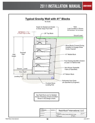
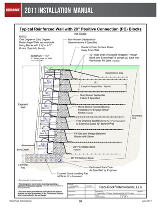
This document provides instructions for installing a Redi-Rock retaining wall. It begins with a pre-construction checklist that outlines important safety, engineering, planning, and material staging considerations. It then provides detailed instructions on constructing the leveling pad, setting the bottom row of blocks, and building successive rows of blocks. Specific guidance is given for open-graded stone, dense-graded stone, and concrete leveling pads. The document emphasizes compaction requirements and proper placement of drainage stone and geotextile fabric.
Alternative Dispute Resolution methods Level III - B.Sc QS (Salford) March ...TheGimhan123
The document discusses alternative dispute resolution (ADR) methods used in the Sri Lankan construction industry. It outlines several reasons for disputes in the industry, including breaches of contract and issues with plans/specifications. The document then describes various ADR methods used, including negotiation, conciliation, mediation, adjudication and arbitration. It notes advantages of ADR methods like minimum delay, confidentiality and lower cost compared to litigation. ADR methods provide fast and cost-effective options for resolving frequent disputes in the construction sector.
1. A site investigation determines the suitability of a site for construction by examining physical aspects like soil composition and legal aspects like planning permissions.
2. The investigation assesses the site suitability, helps with design and construction planning, and predicts potential issues. Information is needed on soil properties, groundwater, and excavated materials.
3. The investigation process involves a desk study of existing information, a site walkover, detailed tests and sampling which may include trial pits and boreholes to examine soil and groundwater conditions.
Arbitration is a quasi-judicial method of settling civil disputes through a decision by one or more arbitrators rather than a court. Under Indian law, arbitration refers to the settlement of civil disputes related to money, property, or contract breaches by a quasi-judicial process with a decision by appointed arbitrators. For arbitration to occur there must be a written agreement between the parties to submit present or future disputes to arbitration, which may or may not name the arbitrator(s). Disputes can be referred to arbitration through the court when no suit is pending or when a suit is already pending.
The document discusses different types of damages in contract law including compensatory damages, liquidated damages, and penalties. It states that compensatory damages aim to put the injured party in the same position as if the contract had been performed, liquidated damages are a pre-estimate of damages from breach but can be penalties if unreasonable, and penalties will not be enforced by courts.
The document provides an overview of the Sales of Goods Act of 1930 in India. Some key points:
- It regulates transactions relating to sales and purchase of goods, repealing sections of the earlier Indian Contract Act of 1872.
- A contract of sale involves the transfer of property in goods from the seller to the buyer for a price. It must have essential elements like buyer, seller, goods, transfer of property, and price.
- The Act defines goods, distinguishes between existing, future and contingent goods, and implied conditions and warranties in a sale.
- It outlines rules around transfer of title, delivery, unpaid sellers' rights including lien, stoppage in transit, and re-sale
An unenforceable contract contains a technical defect that prevents it from being enforced in court, such as a lack of written form or required stamp. Some unenforceable contracts can become enforceable if the technical defect is remedied. An illegal contract involves an act that is criminal, a civil wrong, or against public good, and is void. Money paid under an illegal contract cannot be recovered. A contract can also become illegal if its subject matter is intended for an unlawful purpose.
This document discusses various topics related to earthwork construction including:
1. Definitions of bank cubic yards, loose cubic yards, and compacted cubic yards and how they relate to soil volume changes during excavation and compaction.
2. Methods for calculating swell, shrinkage, load factors, and shrinkage factors to account for soil behavior during earthwork calculations.
3. Traditional and modern methods for calculating earthwork volumes for sitework, highways, and trenches using grids, cross sections, and software.
4. Key factors that influence soil compaction including moisture content, compactive effort, lift thickness, and compaction methods.
The document summarizes the construction process observed at a construction site visited by the authors. It describes the site location and type of buildings being constructed. Safety measures at the site include signage and required protective equipment. Various plants and machinery used at different stages are discussed, including excavators, backhoes, cranes and concrete mixers. Foundations works involving piling and excavations are mentioned.
The document summarizes the Aruba AP-100 Series wireless access points. It describes the key features and specifications of the AP-104 and AP-105 models, which support the 802.11n wireless standard. It provides details on the access points' components, including antennas, ports, LED indicators, and mounting options. It also outlines the steps for installing the access points, including pre-installation planning, identifying installation locations, and connecting the necessary cables.
El documento describe un experimento para observar el movimiento browniano de pequeñas partículas como granos de polen flotando en agua. Explica los materiales necesarios como agua, granos de polen y una lupa, y los pasos del procedimiento que incluyen agregar las partículas al agua y observar su movimiento aleatorio con la lupa.
Este documento presenta la historia de Susanna, una mujer que perdió su negocio, su matrimonio y la relación con sus hijas debido a la infidelidad de su esposo. Susanna se siente enojada y culpabiliza a los demás por su infelicidad. El documento argumenta que el enojo y la falta de perdón destruyen vidas y relaciones. Insta a los lectores a dejar ir el enojo y confiar en que Dios compensará las injusticias, en lugar de buscar venganza.
Los asesinos en serie suelen haber experimentado abusos o negligencia durante la infancia, lo que puede conducir al desarrollo de trastornos de la personalidad como la psicopatía o la sociopatía. A menudo presentan impulsos sádicos y falta de empatía. Matan por compulsión, buscando placer en el sufrimiento ajeno, y pueden coleccionar recortes sobre sus crímenes. Su desarrollo está influenciado por factores genéticos y ambientales que interactúan desde la niñez.
Las mejores herramientas para rockear una página de Facebook.Interlat
Webinar sobre las mejores herramientas y aplicaciones para rockear una página de Facebook.
Con Pablo Di Meglio: www.twitter.com/pablodimeglio
Más info y webinars en http://www.interlat.co/
Mail Server with Filter for organization or school--Project Presentation_(Eng...Sorawit Paiboonrattanakorn
The document describes a science project to create an instant mail server with filtering capabilities for use in schools and organizations. The project aims to develop a web application with a mail server and filters to sort emails for easier searching and access to information. It outlines the hardware, software, and methodology used including laptops, Windows, Linux, databases, and programming tools. Diagrams of the database tables and website interfaces are included. Suggestions are made to expand the filters and integrate LDAP for user data.
The document provides an overview and product listings for Caromed's line of post-surgical compression garments. It describes various garments designed for specific body areas including the head/neck, arms, breasts/chest, waist, and full body. Each garment is made from medical-grade fabrics and designed to provide compression and support during healing from procedures such as surgery, liposuction, and implants.
La historia cuenta la lucha de una madre soltera con 6 hijos pequeños que se quedó sin recursos cuando el padre los abandonó. La mujer trabajó incansablemente buscando empleo y cuidando a sus hijos con muy pocos recursos. Finalmente consiguió un trabajo nocturno en un restaurante gracias a la ayuda de la dueña. En Navidad, cuando no tenía dinero para regalos, clientes del restaurante llenaron su automóvil con ropa y juguetes nuevos para los niños.
Las Medulas es un paisaje cultural en León que contiene los restos de minas de oro romanas a cielo abierto que fueron explotadas entre los siglos I a.C. y II d.C. utilizando ingeniería hidráulica. El Botillo es un embutido típico de la comarca del Bierzo hecho con trozos de cerdo embutidos en el intestino y ahumado. MUSAC en León es un museo de arte contemporáneo ubicado en un edificio de colores llamativos que alberga pinturas y
Key considerations for implementing mobile confirmitMerlien Institute
The document discusses the benefits of implementing a mobile engagement strategy to interact with customers. Mobile adoption is growing rapidly worldwide and changing customer expectations and behaviors. Customers now want interactions to be timely, relevant, and brief via their mobile devices. To maintain relationships, organizations need mobile strategies to engage customers anytime, anywhere. Some benefits include capturing more accurate feedback close to experiences, validating responses with location data and multimedia, and targeting customers based on location. Mobile engagement can make it easier for customers to provide feedback whenever convenient.
The document summarizes Shaklee Life-Strip, a clinically proven daily nutrition supplement. It contains vitamins, minerals, antioxidants, omega-3 fatty acids, and other nutrients shown to support longer life, health, energy and cellular aging. Key ingredients include Vivix polyphenols, OmegaGuard omega-3s, and a proprietary prebiotic and probiotic blend. Taking Life-Strip along with the Shaklee Life Energizing Shake is described as the best comprehensive nutrition system to feel healthier and more energized.
Export Control Training July 31 2009 Export Experts Llc 9 5 09Export Experts, LLC
This document provides an overview of US export control regulations from a presentation given in July 2009. It discusses the various government agencies that regulate exports, including the Departments of Commerce, State, Defense and Treasury. Key points covered include definitions of export controls, license requirements, controlled items on the US Munitions List and Commerce Control List, deemed exports, compliance programs, and penalties for violations. The presentation aims to educate audiences on export controls and compliance.
haiku media è una agenzia multidisciplinare focalizzata alla creazione e realizzazione di progetti di marketing interattivo, con spiccate capacità nello sviluppo tecnologico che questi progetti comportano.
The document discusses the procedures for constructing a building structure. It covers site preparation activities like acquiring permits, clearing the site, and determining the structure location. Earthwork activities like loosening soil, cutting, filling, and compacting are described. The main types of foundations - pad, strip, slab, and pile foundations - are explained in terms of their uses and construction methods. The document provides an overview of the key steps and considerations for structure construction.
This document discusses the psychology and motivations behind sharing content online. It identifies several "personas of sharers", including altruists who share to help others, careerists who share work-related content, hipsters who see sharing as part of their identity, boomerangs who seek engagement through provocative posts, connectors who share to foster relationships, and selectives who only share what they think will be relevant to the recipient. The document also provides credits for the sources of images and studies referenced.
Soil Nails Reinforcement - Design nails soil stabilization --مسامير قضبان تسل...Dr.Youssef Hammida
تثبيت وتسليح - تربة الجدران - الساندة بالمسامير
تستخدم تقنية المسامير في تثبيت المنحدرات الترابية والجدران الاستنادية والأنفاق الى تدعيم حفريات التأسيس العميقة. وتتلخص الطريقة في غرز قضبان معدنية طويلة ذات المقطع الصغيرامام المنحدر المراد تدعيمه بحيث تخترق هذه القضبان كتلة التربة إلى مسافة ونباعدات محددة مثبتة في منطقة خارج مخروط الانهيار حيث يؤمن استقرار سطح التربة على وجه المنحدر بطبقة تغطية رقيقة من الحجر او الخرسانة المقذوفة مسلحة بشبكة معدمية إنشائية مهمتها حجز التربة بين المسامير ويثبت المسمار نفسه على طبقة البيتون المقذوف بصفيحة تثبيت معدنية مربعة الشكل
Soil nail wall - Soil nailing - soil nailing walls
Soil nailing is an earth retention technique using grouted tension-resisting steel elements (nails) that can be design for permanent or temporary support. The walls are generally constructed from the top down. Typically, 3 to 6 feet of soil is excavated from the top of the planned excavation. Near-horizontal holes are drilled into the exposed face at typically 3 to 6 foot centers. Tension-resisting steel bars are inserted into the holes and grouted. A drainage system is installed on the exposed face, followed by the application of reinforced shotcrete facing. Precast face
This document provides installation instructions for stone veneer. There are two main installation methods - standard with grouted joints and jointless/dry-stacked without grouted joints. The instructions cover estimating stone quantities, preparing the surface which depends on the underlying material, mixing mortar, applying the stone by starting at the top and fitting corners first, and finishing by trimming stones and setting them with mortar. Flashing and proper water diversion is important for long-term performance of the stone veneer.
This document provides specifications for constructing modular concrete retaining walls using Allan Block units. It includes sections on product standards, materials, wall construction procedures, and design details. The key points are:
- Allan Block units must meet compressive strength, absorption, and dimensional requirements. Approved wall rock and infill soils are specified.
- Foundation soil is excavated and compacted to 95% standard proctor. The base is installed and leveled for the first course. Subsequent courses are installed by offsetting seams and backfilling with wall rock and infill soil in lifts.
- The consolidation zone, within 3 feet behind the wall, requires compacting in lifts no more than 8 inches thick to 95%
This document is a seminar report on soil nailing submitted by More Abhijit Ashok to Savitribai Phule Pune University in partial fulfillment of the requirements for a bachelor's degree in civil engineering. It discusses the components and construction process of soil nailing. Key aspects covered include types of nails used (driven, grouted, corrosion protected, launched, jet grouted), soil-nail interaction mechanisms, and the typical operations involved in soil nailing construction including placement of nails, grouting, and application of shotcrete facing. The report provides information to understand the technique of soil nailing for engineering applications such as retaining walls and slope stabilization.
The document discusses dowel bar retrofit (DBR), a concrete pavement preservation technique that restores load transfer across joints and cracks in concrete roadways. It does this by installing dowel bars linking adjoining concrete slabs. This prevents faults and stepoffs from forming at joints and cracks, eliminating the rough ride felt when load is not properly transferred. When used with diamond grinding, DBR can return concrete roads to a smooth condition exceeding their original construction quality. The document provides details on how DBR works, its benefits like long lifespan and cost-effectiveness, and considerations for whether a road is a good candidate for the process.
The beam and block flooring system uses precast concrete beams that are laid on foundations to support concrete blocks placed between the beams. This system provides a durable, cost-effective floor that is relatively easy to install without needing specialized skills. At the medical center project, a beam and block flooring system was used along with strip foundations, cavity wall construction, and a flat roof to construct a new single-story extension and remodeling of an existing surgery building.
How to build a besser block wall - APCkristenjames
This document provides instructions on how to build a reinforced Besser block retaining wall. It discusses designing the wall based on loading conditions and soil classification. It specifies materials and provides details on the reinforced concrete base, block laying, grouting, drainage and backfilling. Design details are given for two wall types up to 3m high, including layout, reinforcement sizes and spacing.
The document is a seminar report on soil nailing submitted by Ankush Choudhury to fulfill requirements for a bachelor's degree in civil engineering. It discusses the key components of soil nailing including the nails, shotcrete facing, and interactions between the native soil, reinforcement, and facing. It provides background on the origin and development of soil nailing, favorable ground conditions for its use, design requirements, and construction sequences. The report aims to explain the technique of soil nailing for slope stabilization and retaining walls.
The document provides details from a site visit report for a construction technology course. It includes 10 photos documenting various stages of construction of semi-detached houses. Key aspects summarized include:
- The site visit location and purpose which was to observe construction practices for a 2-story semi-detached housing project.
- Photos showed formwork, scaffolding, machinery used and arrangements of materials on site.
- Descriptions of constructing pad footings including excavation, formwork, reinforcement and concrete pouring.
- The primary construction materials observed were concrete, timber, bricks and reinforcement bars.
This document discusses basement construction using Dincel walls. It provides an introduction to the need for basement wall waterproofing to prevent issues like corrosion, moisture damage, and mold. It then summarizes the benefits of using Dincel walls for basement construction, which eliminates the need for waterproofing membranes and can provide a 100-year wall life. The document also describes different methods for excavating basements, including using shoring with piles or sheet piling, or battering sloped excavation depending on soil conditions.
The document is a site visit report for a construction project comprising 96 residential units. It includes an introduction, objectives of the site visit, summaries of the site layout and house types, and observations of construction materials and methods used - including scaffolding, formwork, pad footings, and reinforced concrete. Photos supplement the technical descriptions and the conclusion reflects on the learning experience gained from directly observing construction practices.
Permeable pavement allows stormwater runoff to filter through voids in the pavement into an underlying stone reservoir, where it is temporarily stored or infiltrated. There are various permeable pavement surfaces like pervious concrete and porous asphalt. The major design goals are maximizing nutrient removal and runoff reduction. Design considerations include soil infiltration rates, structural loading capacity, and reservoir layer sizing. Proper construction and long-term maintenance like periodic vacuum sweeping are required to prevent surface clogging and ensure effective performance.
How to build a besser block wall? View this brochure and know how to. This brochure offers information about retaining wall designs and product specification.
Easy steps to build a besser block wallkristenjames
The document provides guidance on building reinforced Besser block retaining walls and basement walls. It discusses wall designs, including two types of retaining walls up to 3 meters high. It provides details on foundations, materials, construction steps like excavation, block laying and grouting. It also covers drainage, tanking, backfilling and design details like layout, reinforcement and dimensions for level and sloping surfaces.
The document provides technical information for installing Cultured Stone cladding, including estimating stone requirements, materials and tools needed, surface preparation for different substrates, and installation details. It discusses typical installations over timber frame, brick/block, tilt-up panels, and existing walls. Diagrams show installation sequences and details for corners, transitions, windows, facias, and cappings. Estimating stone involves measuring wall area and subtracting openings and areas covered by corners. Surface preparation involves cleaning, priming, and applying expanded metal mesh or mortar to surfaces like timber, masonry, or precast panels before installing the stone cladding.
Ground improvement technic and repair procedures.pdfKumarS250747
Foundation Design requires the knowledge of the behavior of the structure supported by the foundation as well as that of soil or rock that furnishes the ultimate support.
The super structure, foundation and soil or rock must act together and each must posses its unique serviceability and safety in the interactive system
The soil or rock may provide adequate safety of the foundation against failure, detrimental settlement may occur prior to any collapse. Which may be analogous to beam or truss in super structure but does not meet the serviceability(Deflection) criteria
The super structure designs are controlled by the strength of material such as shear strength ,compressive strength and tensile strength but deformations governs the design of foundation.
This document discusses soil nailing and compares glass fiber reinforced polymer (GFRP) soil nails to traditional steel bar soil nails. It provides details on the components and construction sequence of a typical soil nail wall. It outlines several advantages of GFRP soil nails over steel bars, including corrosion resistance, lighter weight, and similar tensile strength. Applications of GFRP soil nails include stabilizing cut slopes, excavations, tunnels, bridges, and existing structures. The document explains that GFRP soil nails provide a more durable and cost-effective alternative to steel due to eliminating corrosion protection needs.
Integrated Assignment - Site Visit ReportYee Len Wan
The document is a site visit report for a construction project building an apartment tower and car park. It includes an introduction describing the project and purpose of the site visit. The technical observation section describes the construction process for pile caps and column stumps including excavation, formwork, reinforcement, concrete pouring, and removal of formwork. Materials used like formwork, reinforcement, concrete spacers and concrete are also detailed. Photos in the appendix further illustrate the construction processes and components observed during the site visit.
Similar to Redi-Rock Installation Manual - Eagle West Precast (20)
The Fred Creek Drainage Improvements project sought to stabilize eroding creek banks in Tulsa, Oklahoma while creating an attractive green space. Redi-Rock retaining walls were used to line the creek and control erosion. The walls were installed in sections to allow the creek flow to be diverted during construction. Finally, native plants were added to create a healthier ecosystem.
This document discusses various water applications for Redi-Rock retaining wall systems, including shoreline protection, marinas, open channels/flood control, water control, retention ponds, culverts & bridges, and river banks. It provides examples of projects utilizing Redi-Rock for these applications and highlights the engineering tools and analysis software available to design Redi-Rock walls for water features. The document also briefly discusses the installation process for Redi-Rock systems.
A one stop resource for Redi-Rock knowledge. Learn about the products aesthetics, design and engineering. See photos of many applications of the product including residential, sea walls, storm channels and railway projects. For further details contact Eagle West Precast Ltd - your exclusive Redi-Rock dealer for the BC Lower Mainland.
Tower Cranes vs. Mobile Cranes - Case History - Eagle West Cranes & EquipmentEagle West Cranes JB
Two similar construction projects used different crane strategies - one with four mobile cranes and the other with two tower cranes on mobile bases. The project using tower cranes saw substantially faster progress due to the cranes' ability to access materials across the large site with fewer units. This prevented delays and reduced costs through improved cycle times and less need for site roads and equipment, increasing revenue.
Eagle West Cranes was hired by Jacob Bros Construction to unload and install a two-piece vault for a highway construction project in Tsawwassen, BC. The site had limited access and soft ground conditions, making the work challenging. An Eagle West operator used a 180-ton crane to lift each vault piece from the truck and set it down at the back of the site. A 125-ton crane was then used to hoist and install the 20,000 pound vault pieces. The project superintendent from Jacob Bros praised Eagle West for their safe and efficient work and plans to hire them for future projects.
Eagle West Cranes was contracted by Imperial Signs Corporation to hoist two large signs approximately 120 feet for installation at the BCIT campus in Burnaby, BC. Using a 40 ton crane with jib and a 14' spreader bar, Eagle West safely completed the one-day project. Imperial Signs' Operations Manager commented that Eagle West is professional, organized, timely, focused on safety, and that they will work with Eagle West again and recommend them to others.
Starting a business is like embarking on an unpredictable adventure. It’s a journey filled with highs and lows, victories and defeats. But what if I told you that those setbacks and failures could be the very stepping stones that lead you to fortune? Let’s explore how resilience, adaptability, and strategic thinking can transform adversity into opportunity.
SATTA MATKA SATTA FAST RESULT KALYAN TOP MATKA RESULT KALYAN SATTA MATKA FAST RESULT MILAN RATAN RAJDHANI MAIN BAZAR MATKA FAST TIPS RESULT MATKA CHART JODI CHART PANEL CHART FREE FIX GAME SATTAMATKA ! MATKA MOBI SATTA 143 spboss.in TOP NO1 RESULT FULL RATE MATKA ONLINE GAME PLAY BY APP SPBOSS
The Most Inspiring Entrepreneurs to Follow in 2024.pdfthesiliconleaders
In a world where the potential of youth innovation remains vastly untouched, there emerges a guiding light in the form of Norm Goldstein, the Founder and CEO of EduNetwork Partners. His dedication to this cause has earned him recognition as a Congressional Leadership Award recipient.
𝐔𝐧𝐯𝐞𝐢𝐥 𝐭𝐡𝐞 𝐅𝐮𝐭𝐮𝐫𝐞 𝐨𝐟 𝐄𝐧𝐞𝐫𝐠𝐲 𝐄𝐟𝐟𝐢𝐜𝐢𝐞𝐧𝐜𝐲 𝐰𝐢𝐭𝐡 𝐍𝐄𝐖𝐍𝐓𝐈𝐃𝐄’𝐬 𝐋𝐚𝐭𝐞𝐬𝐭 𝐎𝐟𝐟𝐞𝐫𝐢𝐧𝐠𝐬
Explore the details in our newly released product manual, which showcases NEWNTIDE's advanced heat pump technologies. Delve into our energy-efficient and eco-friendly solutions tailored for diverse global markets.
Anny Serafina Love - Letter of Recommendation by Kellen Harkins, MS.AnnySerafinaLove
This letter, written by Kellen Harkins, Course Director at Full Sail University, commends Anny Love's exemplary performance in the Video Sharing Platforms class. It highlights her dedication, willingness to challenge herself, and exceptional skills in production, editing, and marketing across various video platforms like YouTube, TikTok, and Instagram.
Unveiling the Dynamic Personalities, Key Dates, and Horoscope Insights: Gemin...my Pandit
Explore the fascinating world of the Gemini Zodiac Sign. Discover the unique personality traits, key dates, and horoscope insights of Gemini individuals. Learn how their sociable, communicative nature and boundless curiosity make them the dynamic explorers of the zodiac. Dive into the duality of the Gemini sign and understand their intellectual and adventurous spirit.
The APCO Geopolitical Radar - Q3 2024 The Global Operating Environment for Bu...APCO
The Radar reflects input from APCO’s teams located around the world. It distils a host of interconnected events and trends into insights to inform operational and strategic decisions. Issues covered in this edition include:
Brian Fitzsimmons on the Business Strategy and Content Flywheel of Barstool S...Neil Horowitz
On episode 272 of the Digital and Social Media Sports Podcast, Neil chatted with Brian Fitzsimmons, Director of Licensing and Business Development for Barstool Sports.
What follows is a collection of snippets from the podcast. To hear the full interview and more, check out the podcast on all podcast platforms and at www.dsmsports.net
The Steadfast and Reliable Bull: Taurus Zodiac Signmy Pandit
Explore the steadfast and reliable nature of the Taurus Zodiac Sign. Discover the personality traits, key dates, and horoscope insights that define the determined and practical Taurus, and learn how their grounded nature makes them the anchor of the zodiac.
Call8328958814 satta matka Kalyan result satta guessing➑➌➋➑➒➎➑➑➊➍
Satta Matka Kalyan Main Mumbai Fastest Results
Satta Matka ❋ Sattamatka ❋ New Mumbai Ratan Satta Matka ❋ Fast Matka ❋ Milan Market ❋ Kalyan Matka Results ❋ Satta Game ❋ Matka Game ❋ Satta Matka ❋ Kalyan Satta Matka ❋ Mumbai Main ❋ Online Matka Results ❋ Satta Matka Tips ❋ Milan Chart ❋ Satta Matka Boss❋ New Star Day ❋ Satta King ❋ Live Satta Matka Results ❋ Satta Matka Company ❋ Indian Matka ❋ Satta Matka 143❋ Kalyan Night Matka..
Discover timeless style with the 2022 Vintage Roman Numerals Men's Ring. Crafted from premium stainless steel, this 6mm wide ring embodies elegance and durability. Perfect as a gift, it seamlessly blends classic Roman numeral detailing with modern sophistication, making it an ideal accessory for any occasion.
https://rb.gy/usj1a2
3. 2011 INSTALLATION MANUAL
PRE-CONSTRUCTION CHECKLIST..................................................................
Before you start construction of a Redi-Rock wall, take the time to complete necessary planning and preparation. This pro-
cess will help ensure a safe, efficient, and quality installation. It will also help avoid costly mistakes.
SAFETY
Safety is of primary concern to Redi-Rock International. Redi-Rock walls must be installed in a safe manner. All local,
state, and federal safety regulations must be followed. In addition, Redi-Rock International greatly encourages installers to
set up company programs to help their people stay safe at work. These programs should address items such as: personal
protective equipment, maintaining safe slopes and excavations, fall protection, rigging and lifting, and other safety precau-
tions. Safety-training materials specific to your company can be found at www.osha.gov or by calling 1-800-321-OSHA
(6742).
ENGINEERING AND PERMITS
Obtain necessary engineering and permits for your project. Your local building department is an excellent resource to help
determine the requirements for your project.
Note: This installation manual is intended to supplement a detailed, site-specific wall design prepared for your
project by a Professional Engineer. The construction documents for your project supersedes any recommenda-
tions presented here.
REVIEW THE PROJECT PLANS
Take the time to review and understand the project plans and specifications. Make sure that the plans take into account
current site and soil conditions. Pay close attention to silty or clayey soils and ground water or surface water on the site.
A pre-construction meeting with the wall designer, construction inspector, wall contractor, and owner or representative is
recommended.
CONSTRUCTION PLANNING
Develop a plan to coordinate construction activities on your site. Make sure your plan specifically addresses how to control
surface water during construction.
UTILITY LOCATION
Make sure to have underground utilities located and marked on the ground before starting any construction. Call 8-1-1 or
go online to www.call811.com to schedule utility marking for your project site.
MATERIAL STAGING
Store Redi-Rock blocks in a location close to the proposed wall. Blocks should be kept clean and mud free. Blocks
should also be stored in a location which will minimize the amount of handling on the project site.
Store geogrid in a clean, dry location close to the proposed wall. Keep the geogrid covered or in the shade and avoid
exposure to direct sunlight.
Be careful where you stockpile excavation and backfill material. Do not stockpile soils over buried utility lines which could
be damaged by the extra weight.
Redi-Rock International 3 June 2011
4. 2011 INSTALLATION MANUAL
EQUIPMENT
Make sure you have the proper equipment to handle Redi-Rock blocks and install the wall. Redi-Rock blocks can weigh
up to 3,500 pounds each. Make sure excavators and other construction equipment are properly sized to handle Redi-
Rock blocks. (Figure 1)
Hand operated equipment should include, as a minimum, shovels, 2’ level, 4’ level, broom, hammer, tape measure, string,
spray paint, laser level, pry bar, walk behind vibratory plate compactor (capable of delivering a minimum of 2000 lb cen-
trifugal force), and a concrete saw. (Figure 2)
Personal protective equipment should include, as a minimum, appropriate clothing, steel toe boots with metatarsal protec-
tion, eye protection, hard hat, gloves, hearing protection, fall protection rigging, and other items as necessary to insure a
safe working environment.
Figure 1 Figure 2
Redi-Rock International 4 June 2011
5. 2011 INSTALLATION MANUAL
SUBGRADE SOILS.........................................................................................
Proper base preparation is a critical element in the construction of your retaining wall. Not only is it important to provide a
stable foundation for the wall, but a properly prepared base will greatly increase the speed and efficiency of your wall instal-
lation. Proper base preparation starts with the subgrade soils.
Existing soils must be removed to the bottom of the leveling pad elevation for the retaining wall. (Figure 3)
The base and back of excavation should expose fresh, undisturbed soil or rock. Remove all disturbed soils which “fall-in”
along the base of the wall or the back of the excavation.
The subgrade soil (below the leveling pad) should be evaluated by the Professional Engineer responsible for the wall to
make sure it meets the design requirements and to determine its adequacy to support the retaining wall. Any unsuitable
material shall be excavated and replaced as directed. Subgrade soils must be compacted to a minimum of 95% maximum
density as determined by a standard proctor test (ASTM D698).
Figure 3
Redi-Rock International 5 June 2011
6. 2011 INSTALLATION MANUAL
LEVELING PAD.............................................................................................
Base preparation continues with proper leveling pad construction. Redi-Rock retaining walls can be designed with an
open-graded crushed stone, dense-graded crushed stone (GAB), or concrete leveling pad which supports the bottom row
of blocks. The choice of which type of leveling pad to use is made by the wall designer and depends on several factors
including the bearing capacity of the native soil, location of the drain outlet, conditions at the base of the wall, and any other
special considerations for the wall.
OPEN-GRADED CRUSHED STONE LEVELING PAD
The most common type of leveling pad
is made using an open-graded crushed
stone with a drain located in the bot-
tom of the stone. (Figure 4) This is
the method that is shown in most Redi-
Rock preliminary or conceptual draw-
ings. An open-graded crushed stone
leveling pad assumes that the wall
drain can drain to daylight (by grav-
ity) somewhere on the site below the
elevation of the bottom of the leveling
pad. If you cannot outlet the wall drain
below the elevation of the bottom of
the leveling pad, you should not use
open-graded crushed stone. Water will
become trapped below the drain outlet,
weakening the base of your retaining
wall and causing other problems.
Leveling pad material should be Figure 4
washed, crushed stone, 1 inch diam-
eter and smaller. A crushed stone meeting the gradation requirements of ASTM No. 57 with no material passing the No.
200 sieve is preferred. The leveling pad thickness shall be as designed by the Professional Engineer. A minimum thickness
of 6” or 12” is common. The leveling pad should extend at least 6” in front and 12” behind the bottom block. Make sure to
check your plans.
A drain is placed in the bottom of the leveling pad to provide an outlet for any water collected behind the wall. A 4” perforated
sock drain is commonly used. The drain runs the entire length of the wall and must have proper outlets to provide drainage
for the wall. (Figure 5)
Figure 5
Redi-Rock International 6 June 2011
7. 2011 INSTALLATION MANUAL
The leveling pad material should be placed and
compacted to provide a uniform, level pad on which
to construct the retaining wall. (Figure 6) Proper
elevation can be established with a laser level or
transit. You can also set two 20’ long grade pipes
to the desired grade and screed the crushed stone
material between the pipes.
Place the stone leveling pad in uniform loose lifts
a maximum of 6” thick. Consolidate the stone with
a minimum of three passes with a 24” wide, walk-
behind, vibrating plate compactor capable of deliver-
ing at least 2000 pounds of centrifugal force. This
should achieve 90% relative density of the stone
determined in accordance with ASTM D-4253 and Figure 6
D-4254. In place density of the stone fill should be con-
firmed using ASTM D-6938. If you don’t achieve a minimum of 90% relative density, place the stone in smaller lifts or apply
more compaction effort until you do achieve 90% relative density of the stone.
Do NOT place a thin layer of sand between the leveling pad and bottom block. This layer will reduce the sliding resistance
between the leveling pad and bottom block.
Redi-Rock International 7 June 2011
8. 2011 INSTALLATION MANUAL
DENSE-GRADED CRUSHED STONE LEVELING PAD
If you cannot outlet the wall drain below the elevation of the bottom of the leveling pad, you need to construct the leveling
pad from material which has a low permeability and will not trap water below the elevation of the drain outlet. In this case, a
dense-graded crushed stone or graded aggregate base (GAB) material is typically used up to the elevation where the wall
drain can gravity outlet through the face of the wall. (Figure 7)
Figure 7
Leveling pad material should be dense-graded crushed stone with between 8 and 20% “fines” which will pass through a
No. 200 sieve. The leveling pad thickness shall be as designed by the Professional Engineer. A minimum thickness of 6”
or 12” is common. The leveling pad should extend at least 6” in front and 12” behind the bottom block. Make sure to check
your plans.
Place the dense-graded crushed stone in uniform loose lifts a maximum of 6” thick. Consolidate the stone with a mini-
mum of three passes with a 24” wide, walk-behind, vibrating plate compactor capable of delivering at least 2000 pounds of
centrifugal force. This should achieve 90% relative density of the stone determined in accordance with ASTM D-4253 and
D-4254. In place density of the stone fill should be confirmed using ASTM D-6938. If you don’t achieve a minimum of 90%
relative density, place the stone in smaller lifts or apply more compaction effort until you do achieve 90% relative density of
the stone.
Make sure the dense-graded crushed stone is placed and compacted to provide a uniform, level pad on which to construct
the retaining wall.
Place the bottom row of blocks on the leveling pad.
Continue wall construction as described in the section “SETTING THE WALL BLOCKS”. However, use dense-graded
crushed stone up to the elevation where the wall drain can gravity outlet through the face or at the ends of the retaining wall.
At this elevation, place a wall drain to provide an outlet for any water collected behind the wall. A 4” perforated sock drain is
commonly used. The drain runs the entire length of the wall and must have proper outlets to provide drainage for the wall.
There are two methods to outlet the drain through the face of the wall. The first method is to sawcut a small notch in the
sides of two adjacent blocks. This makes a small hole for the drain outlet. Place the outlet pipe through the hole and seal
the area between the pipe and Redi-Rock blocks with a non-shrink grout. The second method is to outlet the drain into small
pipes cast through the Redi-Rock blocks. These blocks are custom, special order items. Please coordinate with your local
Redi-Rock manufacturer.
Change from dense-graded to open-graded crushed stone from the elevation of the wall drain up through the rest of the wall.
The stone should be placed as described in the section “SETTING THE WALL BLOCKS”.
Redi-Rock International 8 June 2011
9. 2011 INSTALLATION MANUAL
CONCRETE LEVELING PAD
In some cases, the wall design requires the construction of a concrete leveling pad. (Figure 8a) Construct the leveling pad
according to the detailed plans for your project.
Figure 8a
Your design may also require a shear key in the bottom of the footing and/or a lip in front of the Redi-Rock blocks.
These items would be shown in the project plans. (Figure 8b)
Figure 8b
If steel rebar is to be placed in the footing, secure the bars together with wire ties in the pattern shown in the wall design.
Use rebar supports to hold the rebar structure in the proper position in the footing.
Place wood formwork at the front and back of the concrete leveling pad or footing. The top of the formwork should be placed
at the elevation of the top of the concrete footing so you can screed the top smooth in preparation for block placement.
Place concrete as specified in the wall design.
Once the concrete has been allowed to cure to the minimum specified strength, place the bottom blocks and continue
construction of the retaining wall.
A drain is placed on the top of the concrete footing to provide an outlet for any water collected behind the wall. A 4” perfo-
rated sock drain is common. The drain runs the entire length of the wall and must have proper outlets to provide drainage for
the wall. Refer to the description in the DENSE-GRADED CRUSHED STONE LEVELING PAD section above for descrip-
tions of how to outlet the wall drain through the face of the wall.
Redi-Rock International 9 June 2011
10. 2011 INSTALLATION MANUAL
SETTING THE BOTTOM ROW OF WALL BLOCKS.............................................
Redi-Rock blocks are typically delivered to the construction site using a flat bed trailer or boom truck. (Figure 9) Rubber
tired backhoes, loaders, skid steers, or excavators are used to set the retaining wall blocks. (Figure 10) Redi-Rock blocks
weigh up to 3,500 lbs. Make sure to use the proper sized equipment to handle the blocks. All lifting chains, rigging, or slings
must be OSHA compliant and safety rated for proper working loads.
Figure 9 Figure 10
Properly mark the location of the
retaining wall. A string line or offset
stakes are typically used to establish
horizontal and vertical alignment. If
offset stakes are used, the stakes
should be placed at least 5 feet but
no more than 10 feet in front of the
face of the retaining wall. A stake
should be provided at every eleva-
tion change and at a maximum of 50
feet apart.
Place a complete row of blocks on
the prepared leveling pad. Blocks
shall be placed tight together. Block
alignment should be established by
lining up the “form line” where the
face texture meets the steel form
finished area at the top of the block,
approximately 5 inches back from
the front face. (Figure 11) Figure 11
Check all blocks for level and alignment as they are placed. Small adjustments to the block location can be made with a
large pry bar. If you take the time to set the bottom row properly, installation of the upper rows of blocks is much easier and
more efficient.
TIP: Wall construction should start at a fixed point such as a building wall, 90°
corner, or at the lowest elevation of the wall.
Redi-Rock International 10 June 2011
11. 2011 INSTALLATION MANUAL
Place non-woven geotextile fabric in the vertical joint between the
blocks to hold the backfill material between the blocks in place
and prevent material from “washing out” through the joints be-
tween blocks. (Figure 12)
Place and compact backfill in front of the bottom row of blocks to
help hold them in place.
Place washed drainstone or open-graded crushed stone backfill
between blocks and at least 12 inches behind the wall. (Figure
13) A stone meeting the gradation requirements of ASTM No. 57
with no material passing the No. 200 sieve is preferred. Place
the stone in uniform loose lifts a maximum of 6” thick. Consoli-
date the stone with a minimum of three passes with a 24” wide,
walk-behind, vibrating plate compactor capable of delivering at
least 2000 pounds of centrifugal force. This should achieve 90%
Figure 12
relative density of the stone determined in accordance with ASTM
D-4253 and D-4254. In place density of the stone fill should be confirmed using ASTM D-6938. If you don’t achieve a
minimum of 90% relative density, place the stone in smaller lifts or apply more compaction effort until you do achieve 90%
relative density of the stone.
Figure 13
Place non-woven geotextile fabric between the drainstone and the remaining backfill material if specified.
Backfill behind the washed drainstone with material as specified in the project design. Place the lifts as specified, but not to ex-
ceed 9” maximum. Granular backfill shall be compacted to a minimum of 95% maximum density as determined by a standard
proctor test (ASTM D698). Use proper equipment to ensure complete compaction of the backfill material. It may be necessary
to wet or dry the backfill material, place the material in smaller lifts, and/or apply more compaction effort to reach 95% maximum
density. Do not use any organic, topsoil, frozen, soft, wet, or loose soils when backfilling the wall.
Re-check all units for level and alignment and sweep the top of each course of blocks clean before starting construction of
the next course.
Redi-Rock International 11 June 2011
12. 2011 INSTALLATION MANUAL
SETTING UPPER ROWS OF WALL BLOCKS.....................................................
Place the next row of blocks on top of
the bottom row.
If needed, a half block can be used at
the end of every other row to establish
a running bond in the wall where a Re-
di-Rock block straddles the two blocks
below it. (Figure 14)
Push the Redi-Rock blocks forward
until the groove on the bottom of the
block comes in full contact with the
knobs on the blocks below.
Place non-woven geotextile fabric in
the vertical joint between the blocks,
and place and compact the drainstone
and backfill material the same way you
did for the bottom row. Figure 14
Do not install more than one course of blocks without placing and compacting stone and backfill. Having more than one course
of blocks without backfill will prevent you from being able to properly place and consolidate the stone fill between blocks.
Repeat these steps with each course of blocks to the top of the wall.
IMPORTANT NOTES
If at any time ground water seepage is observed along the exposed excavation behind the retaining wall, contact the wall
designer immediately to determine the corrective action needed.
Once you commence working, continue without interruption or delays. This will help expedite construction and minimize the
time the excavation is open.
The construction site should be graded and maintained to direct surface water runoff away from the retaining wall through-
out the entire construction process. If there is a rain event with surface water runoff producing erosion or scour near the
retaining wall, contact the wall designer immediately to determine the corrective action needed.
Allowable construction tolerance at the wall face is 1° vertically and 1” in 10’ horizontally.
Redi-Rock International 12 June 2011
13. 2011 INSTALLATION MANUAL
STEPS IN A WALL.........................................................................................
STEPS IN THE TOP OF A WALL
Most walls have a grade change
along the top of a wall which requires
stepping down the top blocks. There
are different options available to step
down the top of a wall.
End blocks or garden corner blocks
may be used to make a step-down.
(Figure 15) If desired, the inside lip
can be removed to allow the topsoil
to fill to the edge of the block. To
remove the lip, make one cut with a
concrete saw and knock the lip off
with a sledgehammer.
Figure 15
Top blocks may be placed in a radius to provide a scalloped look. (Figure 16) Two to four half blocks should be used. Re-
move the outside knob on the last middle block of the bottom course before beginning scallop. A concrete saw and sledge-
hammer can be used to remove the knob in the field.
Freestanding corner blocks can be used inline to step-down or finish the end of a wall. A Redi-Rock Step block or Cap Block
can be used to provide a more finished look. (Figures 17 and 18)
Figure 16 Figure 17 Figure 18
STEPS IN THE BOTTOM OF A WALL
Grade changes along the bottom of a wall can be accommodated by stepping the bottom row of blocks.
Steps in the bottom of a wall are relatively simple to make with either a crushed stone or concrete footing. A half bottom
block is used to finish the bottom row before making the step. This accounts for the running bond between rows of blocks
and keeps a middle block from being used at the bottom of the wall. (Figure 19)
Figure 19
Redi-Rock International 13 June 2011
14. 2011 INSTALLATION MANUAL
CORNERS AND CURVES................................................................................
Corners and curves can be made with Redi-Rock walls.
Corners are typically constructed at 90° angles. Smaller or
larger angles in the wall are typically made with curves.
WALLS WITH 90° CORNERS
Corner freestanding blocks are used to make 90° corners.
(Figure 20) If a standard corner block with a straight bot-
tom groove and 6” diameter knobs is used, a small portion
of the knob on the corner block and on the adjacent re-
taining wall block must be sawcut and removed for proper
block alignment. If the special 90° corner block with a
Figure 20
modified (wider) bottom groove and smaller knob is used,
no sawcutting is required.
Start construction at the 90° corner and work away in both directions.
If a double 90° corner is to be constructed, special construction details must be followed to account for the effect of the wall
batter.
There are several construction details available online at www.redi-rock.com which show examples of single and double
90° corners.
CURVED WALLS
Curves can easily be incorporated into a Redi-Rock
wall. (Figure 21)
Concave curves may be installed at varying radii. The
blocks should be placed tight together to make a smooth
curve.
Although there is no fixed minimum radius, smaller radii
(lengths typically less than 14’6”) will result in exposing
more of the untextured top face of the blocks in the un- Figure 21
derlying layer. This may not be visually desirable or ac-
ceptable. (Figure 22)
Convex curves may be installed at varying radii. Redi-Rock blocks are tapered on the sides. The smallest radius you can
make with Redi-Rock blocks (without cutting the blocks) occurs when the blocks are placed together with their sides touch-
ing. The minimum radius for full size blocks is 14’-6” from the face of the blocks. A minimum radius of 8’-0” from the face of
the blocks can be made if all half blocks are used. Note:
you will not have a running bond joint between blocks if
you use all half blocks.
When you are building a multiple course Redi-Rock wall,
each layer of blocks sets back from the blocks below.
Looking down on the top of the wall, you can see that
the radius for each row of blocks gets smaller as you go
higher in the wall. The shortest radius will be on the top
course of the wall.
Figure 22
Redi-Rock International 14 June 2011
15. 2011 INSTALLATION MANUAL
Plan ahead when laying out a curved retaining wall. Start with the minimum radius you want at the top of the wall and then
add 2” per course for each standard setback block, 10” per course for each 9” setback block, and 17” per course for each
planter block in the wall below the top row of blocks. This will make sure that you have enough room at the top of the wall to
build the top row of blocks without interference. Refer to the following chart for minimum bottom radius in Redi-Rock walls.
(Figure 23)
Figure 23
Remember to include the non-woven fabric in the vertical joint between adjacent blocks. If the block spacing becomes too
tight for the non-woven fabric and stone between the blocks, place the non-woven fabric over the joint at the back of the
blocks. (Figure 24)
Figure 24
Redi-Rock International 15 June 2011
16. 2011 INSTALLATION MANUAL
INSTALLING PLANTER BLOCKS.....................................................................
Planter block features may be incorporated into the design of
the wall. Planter blocks are used to provide for vegetation to
break up the face of a wall. (Figure 25) Planter blocks can
also be used without vegetation to increase the wall batter
and help improve stability.
The trough in the planter blocks must be filled with soil, stone,
or concrete, depending on how the planter blocks are used.
In no case shall the trough in the planter blocks be left empty
as backfill from behind the wall can wash out through joints
between the blocks causing voids to form behind the wall.
The planter block has a 16 5/8” setback and is supported Figure 25
partially on the stone backfill material behind the wall. (Fig-
ure 26) It is important that the stone backfill be leveled and
compacted prior to placing the planter blocks. Place the
stone in uniform loose lifts a maximum of 6” thick. Con-
solidate the stone with a minimum of three passes with a
24” wide, walk-behind, vibrating plate compactor capable
of delivering at least 2000 pounds of centrifugal force. This
should achieve 90% relative density of the stone deter-
mined in accordance with ASTM D-4253 and D-4254. In
place density of the stone fill should be confirmed using
ASTM D-6938. If you don’t achieve a minimum of 90% rel-
ative density, place the stone in smaller lifts or apply more
compaction effort until you do achieve 90% relative density Figure 26
of the stone.
In some cases, planter blocks may be transitioned in or out
of a normal middle block course in a wall. This transition is
done by removing one or two knobs at the transition, or by
using the corner block. (Figure 27) Please note that tran-
sitioning planter blocks in or out of a middle block course
may offset the joints slightly from falling in the middle of the
block below.
In general, you want to keep all sources of water away from
your retaining wall. However, if properly designed and con-
structed, planters may be irrigated on a case by case basis
Figure 27
as directed by the Professional Engineer responsible for the
wall design. Place a piece of geotextile fabric over the joint
between planter blocks to eliminate soil from washing out.
(Figure 28)
Figure 28
Redi-Rock International 16 June 2011
17. 2011 INSTALLATION MANUAL
REINFORCED SOIL WALLS USING GEOCONNECTOR BLOCKS...........................
Redi-Rock blocks are designed to
allow you to build relatively tall non-
reinforced or gravity walls which use
the weight of the blocks to provide
stability. In some instances, you may
need to build a wall even taller than
can be achieved using Redi-Rock
non-reinforced walls. In these cases,
reinforced soil walls using a combi-
nation of geogrid soil reinforcement
and Redi-Rock retaining wall blocks
can be used.
Reinforced walls with Redi-Rock 28”
blocks use large sheets of geogrid to
reinforce the soil. (Figure 29) The
sheets of geogrid are connected to Figure 29
the Redi-Rock blocks at the hori-
zontal “geoconnector” groove in the
blocks.
Stability of reinforced soil walls rely on the interaction between geogrid reinforcement, soil in the reinforced zone, and the
Redi-Rock facing blocks. It is very important that reinforced soil walls be constructed per the detailed design prepared by a
Professional Engineer. Make sure you are using the proper type and strength of geogrid listed in the design. The geogrid
layers need to be placed at the proper elevations and to the proper distances into the reinforced soil zone detailed in the
design. It is also critical to use the appropriate backfill material in the reinforced soil zone.
GEOGRID INSTALLATION
Construct the wall up to the elevation of the geogrid layer shown in the design. Before placing geogrid, grind smooth any
rough edges on the back of the concrete blocks prior to placement to avoid damage to the geogrid sheets.
Place geogrid sheets from the wall blocks to the design length at the back of the reinforced soil zone. The distance the
geogrid must extend into the reinforced soil zone is usually measured from the face of the wall to the back of geogrid. As
always, check your plans to make sure.
Use the specified geogrid with the strong or roll direction PERPENDICULAR to the wall face. Geogrid must be placed in a
continuous sheet throughout its length from the connection at the Redi-Rock blocks to the back of the reinforced zone. Do
not splice or overlap the geogrid.
Make the appropriate connection to the Redi-Rock blocks. (See a description of the connection below.) After connecting,
pull the geogrid sheets taut and pin them down prior to placing and compacting backfill.
Place lifts of specified fill material in the reinforced soil zone. The fill material is typically a sand or gravel with less than 5%
“fines” (material passing the No. 200 sieve). This material is usually classified as a GW, GP, SW, or SP. It is very important
that you only use the fill material specified in your project design drawings and specifications.
Perform compaction starting from the back of the wall blocks and working into the reinforced soil zone. This will help avoid
“bunching” the geogrid reinforcement. Material should be placed in lifts of 9” maximum and compacted to 95% maximum
density as determined by a standard proctor test (ASTM D698).
Redi-Rock International 17 June 2011
18. 2011 INSTALLATION MANUAL
Do not operate tracked construction equipment directly on the geogrid reinforcement. A minimum fill thickness of 6” is
required for the operation of tracked vehicles over the geogrid reinforcement. Turning of tracked vehicles should be kept
to a minimum to prevent displacement of the fill and the geogrid reinforcement. Rubber-tired vehicles may pass over the
geogrid reinforcement at a slow speed (less than 5 mph). Sudden breaking and sharp turning should be avoided.
Place retained soil immediately between the reinforced soil zone and the back of the excavation. Material should be
placed in lifts of 9” maximum and compacted to 95% maximum density as determined by a standard proctor test (ASTM
D698). Bring the reinforced and retained soil up to grade at the same time. At no time should the elevation of the rein-
forced soil be more than 1 block higher than the retained soil.
GEOGRID CONNECTION TO BLOCKS
Connection between geogrid sheets and the Redi-Rock 28” Series blocks is made with the Redi-Rock Type 1AT connec-
tion. The connection is made with one 7/16” diameter solid fiberglass rod available from your local Redi-Rock manufacturer.
(Figure 30)
The Type 1AT Connection is made with the following steps:
• Install a complete row of retaining wall blocks. Sweep the top of the blocks clean.
• Lay the geogrid across the top of the block and let it hang down to the bottom of the front face.
• Place one 40” fiberglass rod over the geogrid into the geoconnector slot. (Figure 31)
• Pull the geogrid back over the rod and extend the tail beyond the back of the block to provide a minimum of 3 feet
embedment. TIP: A steel angle can be used to hold the rod and geogrid in position as shown. (Figure 32)
• Install the next course of retaining wall blocks to lock the geogrid connection in place.
• Pull the geogrid flat and tight. Secure it in place with pins or staples as recommended by the manufacturer.
• Place 3 inches of drainstone between the anchored tail and the primary geogrid layer.
• Backfill and compact as specified.
Figure 30
Figure 31 Figure 32
Redi-Rock International 18 June 2011
21. 2011 INSTALLATION MANUAL
DRAINAGE FEATURES IN REINFORCED SOIL WALLS
Drainage features shall be installed per the detailed design prepared by a Professional Engineer. Measures may include
a chimney drain behind the reinforced soil zone if required. (Figure 35) The site should also include drainage swales or
other methods to direct water away from the top and bottom of the wall.
Figure 35
Redi-Rock International 21 June 2011
22. 2011 INSTALLATION MANUAL
REINFORCED SOIL WALLS USING THE REDI-ROCK PC SYSTEM......................
Reinforced walls with the Positive
Connection Series blocks use dis-
crete, 12” wide strips of geogrid to re-
inforce the soil. The strips of geogrid
wrap through a slot cast in the center
of Positive Connection blocks and ex-
tend full length behind the blocks on
both the top and bottom of the block.
(Figure 36)
Stability of reinforced soil walls rely
on the interaction between geogrid
reinforcement, soil in the reinforced
zone, and the Redi-Rock PC blocks.
It is very important that reinforced soil
walls be constructed per the detailed Figure 36
design prepared by a Professional Engineer. Make sure you are using the proper type and strength of geogrid listed in the
design. The geogrid strips need to be installed in the appropriate blocks and to the appropriate length. In most cases, every
PC block in the wall has a geogrid strip. It is also critical to use the appropriate backfill material in the reinforced soil zone.
Review your project design drawings and specifications.
Before constructing a reinforced soil wall using the Redi-Rock PC system, inspect the material delivered to the project site.
The geogrid strips should be properly cut to a 12” width. The size and spacing of main, longitudinal strands vary with type
and weight of geogrid. Check and make sure that you have the correct number of main, longitudinal strands for your geogrid
type and that the outside strands are intact and were not damaged in the manufacturing or cutting process. Check the Redi-
Rock PC blocks for any flashing or sharp edges in the slot and groove through the block. Remove any flashing and grind
smooth any sharp edges which could damage the geogrid strips.
The distance a geogrid strip must extend into the reinforced soil zone, or design length, is measured from the back of the
block to the back of geogrid. The actual cut length of geogrid strip is two times the design length plus an additional length
for the geogrid required in the block. For the Redi-Rock 28” PC blocks, the cut length is 2 times the design length plus 3
feet (2xL + 3’).
GEOGRID STRIP INSTALLATION
Place the bottom row of Positive
Connection blocks on a prepared
leveling pad.
Place the geogrid strips through
the Redi-Rock Positive Connection
blocks. Pin the bottom leg of the
geogrid strip with staples, stakes,
or other appropriate methods. Pull
the geogrid strip tight to remove any
slack, wrinkles, or folds. (Figure 37)
Figure 37
Redi-Rock International 22 June 2011
23. 2011 INSTALLATION MANUAL
Place drainstone backfill (ASTM No.
57) between blocks and at least 12”
behind the wall. This stone will se-
cure the front end of the geogrid strips
in place. (Figure 38) Place the stone
in uniform loose lifts a maximum of
6” thick. Consolidate the stone with
a minimum of three passes with a
24” wide, walk-behind, vibrating plate
compactor capable of delivering at
least 2000 pounds of centrifugal
force. This should achieve 90% rela-
tive density of the stone determined
in accordance with ASTM D-4253
and D-4254. In place density of the
stone fill should be confirmed using
ASTM D-6938. If you don’t achieve
a minimum of 90% relative density,
place the stone in smaller lifts or ap- Figure 38
ply more compaction effort until you
do achieve 90% relative density of
the stone. Place non-woven geotex-
tile fabric between the drainstone and
the reinforced soil zone if specified.
Place lifts of specified fill material in
the reinforced soil zone. (Figure 39)
The fill material is typically a sand
or gravel with less than 5% “fines”
(material passing the No. 200 sieve).
This material is usually classified as a
GW, GP, SW, or SP. It is very impor-
tant that you only use the fill material
specified in your project design draw-
ings and specifications.
Perform compaction starting from the
back of the wall blocks and working
Figure 39
into the reinforced soil zone. This will
help avoid “bunching” the geogrid reinforcement. Material should be placed in lifts of 9” maximum and compacted to 95%
maximum density as determined by a standard proctor test (ASTM D698).
Tracked construction equipment shall not be operated directly on the geogrid strip reinforcement. A minimum fill thickness
of 6 inches is required for the operation of tracked vehicles over the geogrid strips. Turning of tracked vehicles should
be kept to a minimum to prevent displacement of the fill and the geogrid strips. Rubber-tired vehicles may pass over the
geogrid strips at a slow speed (less than 5 mph). Sudden breaking and sharp turning should be avoided.
After placing backfill to the elevation of the geogrid strip at the top of the block, stretch the top leg of the geogrid strip to the
back of the reinforced soil zone. Pull the geogrid strip tight to remove any slack, wrinkles, or folds. Pin the top leg of the
geogrid strip with staples, stakes, or other appropriate methods to hold it in place and keep the geogrid strip taut.
Fill the center core in the PC blocks with drainstone.
Redi-Rock International 23 June 2011
24. 2011 INSTALLATION MANUAL
Place retained soil immediately be-
tween the reinforced soil zone and
the back of the excavation. Material
should be placed in lifts of 9” maxi-
mum and compacted to 95% maxi-
mum density as determined by a stan-
dard proctor test (ASTM D698). Bring
the reinforced and retained soil up to
grade at the same time. At no time
should the elevation of the reinforced
soil be more than 1 block higher than
the retained soil.
Sweep the top of the Redi-Rock
blocks clean and then continue set-
ting the next course of blocks follow-
ing this same procedure. (Figure 40)
Figure 40
Redi-Rock International 24 June 2011
25. 2011 INSTALLATION MANUAL
GEOGRID STRIP PLACEMENT ON CONCAVE CURVES AND INSIDE CORNERS
Figure 41
Redi-Rock International 25 June 2011
26. 2011 INSTALLATION MANUAL
GEOGRID STRIP PLACEMENT ON CONVEX CURVES AND OUTSIDE CORNERS
Figure 42
Redi-Rock International 26 June 2011
27. 2011 INSTALLATION MANUAL
DRAINAGE FEATURES IN PC SYSTEM REINFORCED SOIL WALLS
Drainage features shall be installed per the detailed design prepared by a Professional Engineer. Measures may include
a chimney drain behind the reinforced soil zone if required. (Figure 43) The site should also include drainage swales or
other methods to direct water away from the top and bottom of the wall.
Figure 43
Redi-Rock International 27 June 2011
28. 2011 INSTALLATION MANUAL
FREESTANDING WALLS
Figure 44 Figure 45
Redi-Rock freestanding wall blocks have facing texture on two or three sides. They are used in applications where two
or three sides of the wall are visible. Freestanding blocks can be installed as “stand alone” walls, such as perimeter walls
or fences. (Figure 44) They can also be designed and installed as top courses on a standard Redi-Rock retaining wall.
(Figure 45)
Freestanding wall installation is similar to Redi-Rock retaining wall blocks. The main exception is that there is typically no
backfill material behind the freestanding walls. Even though there is no backfill acting on the walls, freestanding walls need
to be properly engineered. They require adequate stability at the base of the wall and they need to resist any applied forces
such as wind loads or forces from railings or fences.
FREESTANDING WALL INSTALLATION
If you are building a “stand alone” freestanding wall, pre-
pare the subgrade soils and leveling pad as described
previously. Place bottom blocks on the leveling pad. A 6”
minimum bury on the bottom block is typical. Middle and
top blocks are placed directly on top of the bottom blocks
with no batter.
If you are building a freestanding wall on the top of a
Redi-Rock retaining wall, end the last row of retaining wall
blocks with a middle block. The size of the knob on top
of the last row of retaining wall blocks will establish the
setback for the first row of freestanding blocks. Retaining
blocks with a 10” knob will produce a 2 7/8” setback be-
tween the retaining block and the first freestanding block.
If the retaining blocks have a 7 ½” knob, the setback be- Figure 46
tween the retaining block and the first freestanding block
will be 1 5/8”. (Figure 46) Remember, the 10” diameter knobs are standard on most Redi-Rock retaining wall blocks. Be
sure to contact your local Redi-Rock manufacturer to determine availability of specialty blocks and specify which knob size
you require for your project.
Redi-Rock International 28 June 2011
29. 2011 INSTALLATION MANUAL
FREESTANDING WALL NOTES
Start and end freestanding walls with straight blocks. Three sided
curved blocks are not available.
Freestanding walls are installed with no batter.
A wall constructed with all freestanding curved blocks will have a ra-
dius of 14’ 6”. A wall constructed with alternating straight and curved
freestanding blocks will have a radius of 29’ 0”. Other radii can be
constructed by cutting the ends of the freestanding blocks to fit. Re-
di-Rock freestanding blocks with the 4” x 12” end insert are designed
to be easier to cut in the field. (Figure 47)
Colored foam “Backer Rod” can be used to fill any small gaps which Figure 47
may occur between the blocks when installing walls. (Figure 48)
Backer rods diameter can be purchased from concrete supply cen-
ters. Call your local Redi-Rock manufacturer for help locating foam
backer rods for your project.
CAP INSTALLATION
Cap blocks are commonly used on top of freestanding walls to pro-
vide a “finished” look to the project.
Mark the center of the freestanding blocks to monitor the correct run-
ning bond spacing.
Place a minimum of two beads of construction adhesive on top of Figure 48
the freestanding block before setting the cap block. (Figure 49) Use
an adhesive that meets the requirements of ASTM D3498 and C557
and HUD/FHA Use of Materials Bulletin #60. An example is Titebond
Heavy Duty Construction Adhesive by Franklin International (1-800-
347-4583) or PL Premium Construction Adhesive (www.stickwithpl.
com). Mortar cement can also be used.
Three sided caps should be used on the end of walls. Two sided
caps should be used in the middle of walls. Caps can be cut as
needed for proper alignment.
If desired, grout the joints between cap blocks after installation with
a non-shrink grout. Figure 49
TIP: A Probst Quick Lift may be used for easier installation of
cap blocks or freestanding top (flat) blocks. (Figure 50)
Figure 50
Redi-Rock International 29 June 2011
30. 2011 INSTALLATION MANUAL
FORCE PROTECTION WALLS.........................................................................
Redi-Rock freestanding blocks can be manufactured with horizontal and vertical conduits cast into the blocks, producing the
Redi-Rock Force Protection Series blocks. The conduits create holes in the blocks which provide the ability to connect the
blocks together with post-tensioned cables and j-bolts. The resulting wall section provides more resistance to small impact
loads than individual blocks alone. While not intended to be used as a traffic barrier subject to typical vehicle impact loads,
properly constructed Force Protection Series walls are used in many applications where the wall designer wants the extra
stability from the connected blocks.
Note: Full scale crash testing has not been performed on the Redi-Rock Force Protection Series, thus the system is not rated to any
testing standard. There are computer simulations of vehicle impacts to Force Protection walls available at www.redi-rock.com.
Note: The following are individual line item steps to describe the installation of the post-tensioned cable and j-bolts. In
practice, the cable is threaded through the blocks and j-bolts are installed simultaneously as the blocks are placed.
POST-TENSIONED CABLE INSTALLATION
Install a threaded termination end on the end of the cable. Electroline M Series
terminations manufactured by Esmet, Inc. work well.
Thread cable with termination end through all the blocks. It is important that the
cable is placed in each course of blocks prior to placing the next course.
Pull the cable through the block on the far end of the wall until approximately 2”
of threads protrude beyond the end of the blocks. This 2” of exposed threads will
provide room to place a 5/8” x 6” x 9” steel plate over the exposed threads and
start the nut.
Mark and cut the cable at the starting end of the wall so that 4” of cable protrudes
beyond the block. The 4” protrusion will provide room to install a 5/8” x 6” x 9” steel
plate and ferrule termination fitting. Figure 51
After the cable has been cut, slide the entire cable several feet towards the ferrule end so that you will have room to work.
Install a steel plate and ferrule termination end on the cable.
Pull the cable snug so that the ferrule is against the steel plate. There will be 2” of thread exposed at the far end of the wall
which has the termination end on the cable.
Place the steel plate over the threads and start the nut. The nut can be tightened to the desired tension. (Figure 51)
J-BOLT INSTALLATION
Before placing bottom row of blocks, augur hole and pour in place 10” x 3’ deep
concrete anchor with ½” rebar hook.
Set the bottom block.
Install J-bolt in ground anchor and lean against block.
Set an adjacent block.
Place a clip between blocks in hooks provided on block ends.
Place a J-bolt through center of the clip, thread a nut on J-bolt, and tighten.
For next courses of block, repeat this procedure but connect J-bolt to lower block
instead of ground anchor. (Figure 52) Figure 52
Redi-Rock International 30 June 2011
32. 2011 INSTALLATION MANUAL
REDI-ROCK COLUMNS..................................................................................
Figure 53 Figure 54
Redi-Rock column blocks are available to complement Redi-Rock walls. Columns can be installed by themselves or with
fences or gates. (Figures 53 and 54)
COLUMN AND FENCE INSTALLATION
Prepare base and leveling pad per design details.
Bury columns per design details. Minimum bury at the bottom of the column
block should be at least 2 inches. Extra bury may be required in your design
depending on site conditions and application.
Place the bottom column block, then install concrete fence rails or split wood
fence rails. (Figure 55)
Install pocket plugs above or below fence rails as needed.
Figure 55
Install subsequent courses of column blocks. Use a concrete adhesive or
mortar cement to fasten column blocks together.
Install a column cap on the top course using concrete adhesive or mortar ce-
ment. (Figure 56)
COLUMN AND GATE INSTALLATION
Measure the gate and mark the location on the ground. Leave enough room
for the gate, hinges, and other mounting hardware.
Prepare the base and leveling pad per design details.
Figure 56
Place the column blocks.
Insert gate hinge or latch hardware into the columns at the appropriate elevations.
Mount gate on hinges and adjust to level gate.
Fill the core through the column blocks with concrete. A conduit can be left through the core if needed for lighting, etc.
Finish the column with a column cap. Adjust the cap position until all sides are equidistant and square to the column.
Secure the column cap with mortar, construction adhesive or concrete fill as appropriate.
Redi-Rock International 32 June 2011
33. 2011 INSTALLATION MANUAL
REDI-ROCK PAVERS.....................................................................................
Figure 57 Figure 58
Redi-Rock pavers can finish your hardscape installation. Installation is completed in the following steps:
Grade and compact sub-base material as specified in the project design.
Place and compact a gravel base course. A typical thickness of the gravel base course is 4” to 6”, depending on your application.
Place and compact a sand leveling course beneath pavers. A typical thickness of the sand course is 1” to 1 ½”, compacted
and screeded smooth. (Figure 57)
Install pavers per the project design. Pavers may be placed using slings. After placing pavers and removing slings, nudge
pavers into their final position with an excavator. A vacuum lift is also an effective method to set pavers.
Place two coats of concrete sealer after paver installation.
Curved pavers come standard with textured sides. Three curved pavers in a row can turn a 90° corner, or a 7’ 6” inside
radius.
Pavers may be placed using the mortarless joint sides.
If pavers are used in light traffic situations, sweep sand into the joints to lock
them into place. (Figure 58) Failure to sweep sand into the joints may allow
the pavers to move and result in the concrete chipping at the top edge of the
pavers.
Paver joints may be sprayed with weed killer to eliminate grass or vegetation
growth.
If textured sides are used on pavers, approximately 1 ½” joints may be filled
with grout or filler sand, depending on the application. Do not use grout for
light traffic loading situations as the grout may pop or crack under the traffic
loading.
Pavers may be cut to fit special applications with a concrete chop saw. Figure 59
Manhole covers, valve top boxes, or other embedded items may be special ordered cast-in-place. (Figure 59)
Redi-Rock pavers have an optional 1’ x 1’ joint pattern on a 2’ x 2’ x 2 ½” paver for a specialized edging treatment. These
pavers can be easily cut to fit in customized applications. Check with your local Redi-Rock manufacturer for availability.
Redi-Rock International 33 June 2011
34. 2011 INSTALLATION MANUAL
block details A sample of available Block Details.
Visit www.redi-rock.com for a complete listing.
Redi-Rock International 35 June 2011
50. 2011 INSTALLATION MANUAL
construction
details A sample of available Construction Details.
Visit www.redi-rock.com for a complete listing.
Redi-Rock International 51 June 2011