
Recommended
More Related Content
What's hot
What's hot (20)
Similar to Allan block Installation guide
Similar to Allan block Installation guide (20)
More from kristenjames
More from kristenjames (20)
Recently uploaded
Recently uploaded (20)
Allan block Installation guide
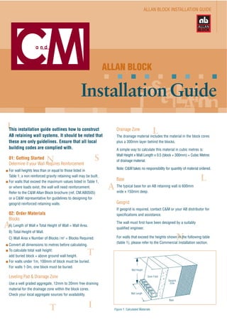
- 1. ALLAN BLOCK INSTALLATION GUIDE ALLAN BLOCK InstallationGuide This installation guide outlines how to construct AB retaining wall systems. It should be noted that these are only guidelines. Ensure that all local building codes are complied with. 01: Getting Started Determine if your Wall Requires Reinforcement For wall heights less than or equal to those listed in Table 1, a non reinforced gravity retaining wall may be built. For walls that exceed the maximum values listed in Table 1, or where loads exist, the wall will need reinforcement. Refer to the C&M Allan Block brochure (ref. CM.AB0505) or a C&M representative for guidelines to designing for geogrid reinforced retaining walls. 02: Order Materials Blocks A) Length of Wall x Total Height of Wall = Wall Area. B) Total Height of Wall. C) Wall Area x Number of Blocks /m2 = Blocks Required. Convert all dimensions to metres before calculating. To calculate total wall height: add buried block + above ground wall height. For walls under 1m, 100mm of block must be buried. For walls 1-3m, one block must be buried. Leveling Pad & Drainage Zone Use a well graded aggregate, 12mm to 20mm free draining material for the drainage zone within the block cores. Check your local aggregate sources for availability. Drainage Zone The drainage material includes the material in the block cores plus a 300mm layer behind the blocks. A simple way to calculate this material in cubic metres is: Wall Height x Wall Length x 0.5 (block + 300mm) = Cubic Metres of drainage material. Note: C&M takes no responsibility for quantity of material ordered. Base The typical base for an AB retaining wall is 600mm wide x 150mm deep. Geogrid If geogrid is required, contact C&M or your AB distributor for specifications and assistance. The wall must first have been designed by a suitably qualified engineer. For walls that exceed the heights shown in the following table (table 1), please refer to the Commercial Installation section. Figure 1: Calculated Materials Wall Height Wall Length Drain Field Geogrid Zone Base
- 2. Figure 2: Start Wall at Lowest Elevation Stepped BaseSloping Grade Start Here Figure 3: Excavate the Base Trench Width = 600mm Depth = 150mm for base plus embedment required as per step 2. 03: Excavate Base Trench and Geogrid Zone Excavate base trench at the wall location. Make sure the trench is level and to the proper depth (Figure 3). Walls built on a sloping grade will require a stepped base (Figure 2). Begin excavation at the lowest point and dig a level trench into the slope until it is deep enough to accommodate the 150mm Base Material and the recommended depth of block embedment. Step up the height of one block and repeat. For geogrid walls, excavate behind the wall far enough to fit the geogrid length, and a safe buffer beyond this zone. 04: Install Base Material Place 150mm base material in the base trench and rake smooth. Compact with a mechanical plate compacter (Figure 4). Check the entire length for level and adjust as needed. 05: Install Base Course Begin at the lowest wall elevation (Figure 2). Place the first row of AB blocks on the Base Material with the raised front lip facing up and forward to the front of the wall. Check and adjust the level and alignment of all blocks. Check levels frequently, side-to-side and front-to-back. Verify the proper position of all blocks by examining a straight line across the back of the blocks or the back of the lips (Figure 5). Make minor adjustments by tapping the block with a rubber mallet or by placing small amounts of coarse sand underneath. Irregularities in the base course become larger as the wall stacks up. Careful attention to a straight and level base course will ensure a quality finished wall. 1 4 5 kPa Poor Soils (25˚) Including sands, gravelly clays, sandy clays & silt clays Average Soils (30˚) Including well graded sands & gravelly sands Good Soils (35˚) Including gravels, sandy gravels & crushed sandstone Poor Soils (25˚) Including sands, gravelly clays, sandy clays & silt clays Average Soils (30˚) Including well graded sands & gravelly sands Good Soils (35˚) Including gravels, sandy gravels & crushed sandstone Poor Soils (25˚) Including sands, gravelly clays, sandy clays & silt clays Average Soils (30˚) Including well graded sands & gravelly sands Good Soils (35˚) Including gravels, sandy gravels & crushed sandstone Backfill Friction Angle, φ 600 600 800 800 1000 AB Junior AB Aussie AB Vertical AB Classic AB Stones 800 800 800 1000 1400* 800 800 1000 1200 1500* 400 400 400 400 400 600 600 600 600 800 600 600 800 800 800 400 400 400 400 600 400 400 600 600 800 800 800 800 800 1000 Job Site Level Above Wall Surcharge of 5 kPa (Driveway) Slope Above Wall in Excess of 1 in 4 & Surcharge of 1.5 kPa Slope Above Wall *Wall Heights achieved by replacing granular fill (in drainage zone) with ‘No Fines’ concrete Table 1: Maximum Heights(mm) for Allan Block - without grid Allan Block Gravity Walls only up to 1.5m maximum height in accordance with AS4678-2002 Figure 4: Compact Base Material Compact Base Material Level
- 3. 06: Install Drainage Material Place an agricultural pipe at the bottom rear of the drainage field with appropriate fall to designated drainage point. Fill the AB hollow cores and the 300mm drain field behind the wall with drainage material. Proper placement of drainage material serves three important purposes. First, the material creates a positive interlock between the blocks. Second, it increases structural stability. Finally, it permits the release of water pressure from behind the wall. 07: Backfill and Compact Compaction of the material behind the wall is critical for a quality wall installation. Use select backfill behind the drain field. Heavy clays and organic materials are not recommended due to their water holding properties. Use a plate compacter to consolidate the aggregate in the block cores and lock the base course in place. The first pass of the plate compacter should be directly over the top of the block cores (Figure 7). After running the plate compacter on top of the base course and drain field, compact the backfill material immediately behind the wall. Compact in a path parallel to the wall, working from the front of the wall to the back of the backfill material (Figure 7). Compact in 200mm lifts. Use only light weight equipment within 1.2m of the wall face. Check the base course for level and adjust as necessary. 08: Install Second & Subsequent Courses Remove all excess drainage material and stone from the top surface of the blocks. This prepares a smooth surface for placement of the next course of AB. Stack the next row of block with the vertical joints offset from the block below. Sight down the wall line to check for a straight wall. Block may be adjusted to form straight lines and smooth curves. Check for level before installing drainage and backfill materials. Adjust as necessary. Repeat steps 6 to 8, installing drainage and backfill material and compacting parallel to the wall face from front to back. For non reinforced gravity walls, repeat steps 6 to 8 to the top of the wall then proceed to step 12. For walls needing reinforcement, follow the steps below. 09: Install First Layer of Geogrid Cut sections of geogrid to specified length. The wall must first have been designed by a suitably qualified engineer. Check manufacturer’s grid specifications for strength or machine direction of the geogrid. Place geogrid behind the block lip with the machine direction extending back into the slope (Figure 8). Place next course of blocks on top of the geogrid. Pull on the back of the grid to remove any slack. Stake in place before installing drainage and backfill material (Figure 9). Figure 8: Determining Geogrid Direction Figure 5: Install Base Course String line Adjust with a rubber mallet Level Figure 6: Install Drainage Material & Backfill Soils Drainage Material Figure 7: Compact Drainage Material & Backfill Soils Infill soils Fill void in front of block Compact parallel to wall Machine Direction
- 4. Figure 12: Ending & Topping Walls CapMulch Lawn Filter Fabric Filter Fabric Filter Fabric 10: Backfill & Compact Place drainage material in blocks and 300mm behind the blocks. Place a 200mm layer of backfill soil on top of the geogrid. All drainage material in the drain field and infill soils within 1m of the wall must be properly compacted using a walk behind plate compacter. Compact in maximum 200mm lifts, starting on the wall and working in a path that runs parallel to the wall towards the back of the reinforced zone (Figure 10). Never operate compacting equipment directly on geogrid. All heavy equipment must be kept at least 1.2m from the wall face (figure 11). 11: Install Additional Courses Repeat steps 7 through 10. Each lift of drainage and backfill material should be installed in the same manner. Compact in lifts of 200mm, the height of one AB unit (Figure 10). Check block for level after compacting each lift, and adjust as needed. 12: Ending and Topping Walls AB's patented raised front lip provides a built-in edging for landscape rock, mulch, grass, soil or AB Cappers (Figure 12). Place filter fabric between the drainage zone and landscaped zone. Walls with step down can be easily finished by turning the ends back into the hillside (Figure 13), or using a cornerstone with a split end as the last unit before step down. 13: Grading and Water Management Grade backfill to ensure that water drainage from the entire site flows away from the wall. A drainage swale can also be incorporated above the wall to divert water away from the top of the wall. Erosion at the end of the wall can be prevented by rolling the end of the wall into the bank (Figure 13). As a general rule bury 500mm of block into the hillside to prevent potential problems. For projects where excessive water run off above the wall is a factor (parking lots, roof drains, etc.) the top of the wall must be finished off to prevent the penetration of water. To ensure that water run off from above the retaining wall does not saturate the soil behind it, a 150mm (min.) layer of impermeable fill should be placed on top of the entire run off area. Install an agricultural drain pipe at the bottom of the drainage field and vent away from wall to remove excess water. Figure 9: Install First Layer of Geogrid Figure 10: Compact in 200mm Lifts Figure 11: Keep Heavy Equipment 1.2m from the wall face Figure 13: Final Grading & Topping Off the Wall Options Set second course on top of Geogrid Keep heavy equipment 1.2m from the wall face Compact in 200mm lifts Pull back Geogrid and stake in place Place cut edge of grid flight against lip Flowing turn-in of wall For a step-down that doubles as a planter, turn the wall in 2 or 3 blocks after the AB Cornerstone. For a natural flow into the landscape, curve the wall back into the hillside.
- 5. 14: Curves Curves and serpentine walls are easy to build. Walls designed with curves complement natural landscape forms and are easy to build. To create outside curves, simply remove the 'wings' from the back of the Allan Block units and tighten the radius of the curve. For setback walls a slight coning will occur on curved walls. Design curved walls so the radius at the top of the wall is at least 1.2m. Refer to the table below to find the minimum recommended radius at the wall base while maintaining a 1.2m radius at the top of the wall. 15: Terraces In some cases it is preferable to terrace a site rather than construct a single wall as this allows for garden beds and stairs between levels to be incorporated into the landscape design. Although terracing improves the look of the landscape, it is important to consider the pressure of the upper wall on the lower wall. The distance between the walls must be greater than 1.5 times the height of the lower wall to ensure the top terrace does not apply loads to the lower wall. This does not take into account global stability issues which need to be considered. Terraced hillsides may require engineering assistance. Contact C&M or your local distributor for more information. Wall Height 1.43m 1.52m 1.6m 1.7m 1.2m 1.8m 2.4m 3.0m 1.55m 1.66m 1.8m 1.9m 1.67m 1.8m 2.0m 2.1m Figure 14: Remove wings for outside curves H2 D H1 Figure 15: Terraced Walls - No Reinforcement Required (if walls are below heights shown in Table 1). Keep the front of the blocks tight together Inside Curve Outide Curve Consistent spacing Setback 3˚ 6˚ 12˚ Use this chart to find the minimum recommended radius at base of wall. Table 2: AB Radius Chart
- 6. Figure 16: Outside Corners Figure 17: Outside Corners 16: Corners When building corners, start from the corners and build away. Soft corners are easier to build than angles. Always avoid small block cuts at the corners. Outside Corners Outside corners are formed by reversing the directions for each course of cornerstone. They must be ordered as right hand or left hand units. Inside Corners Inside corners are easily constructed by modifying Allan Block units (figure 17). Remove half of the raised front lip. They can be chiselled off, but a masonry saw works best. Lay the modified block perpendicular to another Allan Block unit with the lips lined up. Remove the opposite half of the lip of another AB unit and position it over the right angle corner. On each successive row, simply reverse the position of the modified block to obtain an interlocked corner. Step 1 Step 1 Step 1 Ensure base is level going both directions Remove notch to form corner Area of front lip removed Blocks with part of lip removed Step 1 Step 2 Remove part of front lip so next course will seat properly
- 7. Figure 23: Step Tread Options 17: Steps Always check local code requirements before building an type of step application. The steps (figures 18 - 22, left) are general guidelines for building steps. By understanding the basic installation elements, steps can be easily incorporated into the wall installation. Before excavation can begin, the rise and run of the step treads must be determined and code requirements must be met. With that information, the entire base trench can then be excavated. Some examples of different step tread options are illustrated below (figure 23). Our example (figures 18 - 22, left) uses a base trench of 150mm and a step tread of AB cappers and pavers. Excavate to the necessary depth and width for each step riser (figure 18) and thoroughly compact the entire area with a mechanical plate compactor. Check for level. Starting at the first step, fill the base trench with 150mm of drainage material. Rake smooth. Compact and check for level. Steps need extra compaction to avoid any settling later. Better compaction is achieved by backfilling and compacting in 100mm lifts or less when able. Install blocks on the base material. Allow for a space of at least 150mm behind the blocks for drainage material (figure 19). Adjust for level and alignment of each block as it’s installed. Install drainage material in the block cores, fill any space in front of and behind the block. When backfilling behind the blocks, fill the entire area that was earlier excavated to create the base for the next step riser. This should produce a level base for the next set of risers. We recommend backfilling and compacting behind the block in 100mm lifts to achieve better compaction when able. Rake drainage material smooth and compact with the first pass of the compactor directly on the tops of the block and then working in a path that runs parallel to the block (figure 20). Repeat this process for each additional course of steps needed (figures 21 & 22). AB Cappers AB Cappers & Pavers Pavers Concrete Figure 18: Step 1 Figure 19: Step 2 Figure 20: Step 3 Figure 21: Step 4 Figure 22: Step 5 Rise Base Trench Run 150mm Excavate for steps and compact Install and level blocks on base material Backfill block cores and behind block with drainage material & compact Install next step course 150mm Step tread depth Continue for each new step 150mm Step tread depth Next step Install cappers and paver treads. Use sand under the pavers to level with AB Cappers
- 8. ALLAN BLOCK Installation Guide - Ref: CM.ABIN0905 Important: Please consult with the appropriate council for local design and construction of a retaining wall. Councils in general require that retaining walls be designed and certified by a suitably qualified engineer where the wall is over 500mm in height and/or where there is a load such as a road, driveway, house, building or hydrostatic pressure. Patents: Allan Block Retaining Wall Systems are protected by the Australian patent numbers 682394 and 133306 CM0504_K4027 Melbourne - Essendon (Head Office) 264 Keilor Road North Essendon, VIC 3041 phone: 03) 9375 8500 I fax: 03) 9374 4736 C&M Brick Pty Ltd ABN: 14 055 701 034 www.cmbrick.com.au Bendigo 69 Collins Street Kangaroo Flat, VIC 3555 phone: 03) 5447 8866 I fax: 03) 5447 0399 Canberra 6 Tennant Street Fyshwick, ACT 2609 phone: 02) 6239 1255 I fax: 02) 6280 7284 Melbourne - Campbellfield 194 Northbourne Road Campbellfield, VIC 3061 phone: 03) 9305 0900 I fax: 03) 9303 9035 Newcastle Old Maitland Road Sandgate, NSW 2304 phone: 02) 4967 3611 I fax: 02) 4960 1187 Nowra 270-274 Princes Hwy South Nowra, NSW 2541 phone: 02) 4421 3500 I fax: 02) 4421 3082 Queensland 5 Demand Avenue Arundel, QLD 4211 phone: 07) 5571 6644 I fax: 07) 5571 6644 South Australia Cnr Grand Junction & Blakeney Rds Ottoway, SA 5013 phone: 08) 8304 2323 I fax: 08) 8341 1101 Sydney - Moorebank 20 Kelso Crescent Moorebank, NSW 2170 phone: 02) 9822 6822 I fax: 02) 9601 7446