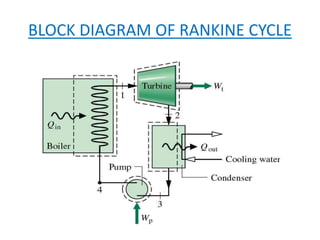
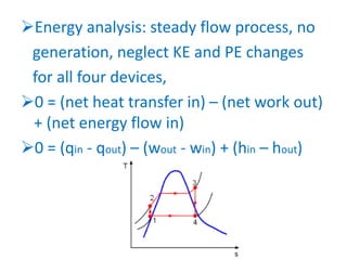
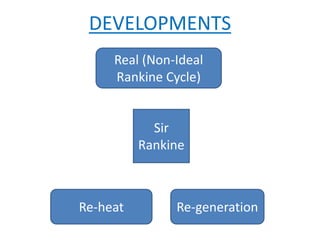
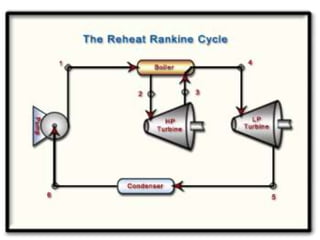
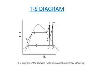
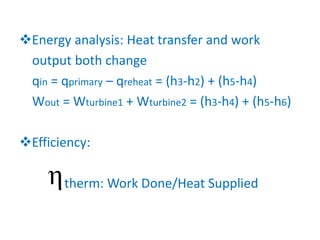
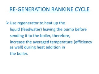
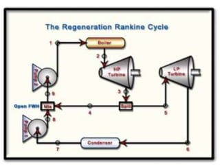
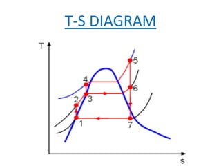
GOVERNMENT ENGINEERING COLLEGE
BHUJ
RANKINE CYCLE
A PART OF VAPOUR CYCLE
Submitted to:
Prof.: R.B.Raval
• Presented by:
CONTENTS
Introduction & Definition
Types of Rankine Cycles
Why we use Rankine Cycle?
INTRODUCTION & DEFINITION
• Rankine is a scottish CIVIL ENGINEER,physicist
and mathematician. He was a founding
contributor, with Rudolf Clausius and William
Thomson, to the science of thermodynamics,
particularly focusing on first law of
thermodynamics.
• The Rankine cycle is a cycle that
 converts heat into work. The heat
is supplied externally to a closed loop,
which usually uses water. This cycle
generates about 90% of all electric
power used throughout the world.
TYPES OF RANKINE CYCLE
Ideal Rankine Cycle
Re-heat Rankine Cycle
Re-generation Rankine Cycle
BLOCK DIAGRAM OF RANKINE CYCLE
IDEAL RANKINE CYCLE
In a real Rankine cycle, the compression
by the pump and the expansion
in the turbine are not ISENTROPIC.
In other words, these processes are
NON-REVERSIBLE and entropy is increased during
the two processes. This somewhat increases
the power required by the pump
and decreases the power generated by
the turbine.
So, the other Engineer’s and Sir Rankine
make it modify.
Energy analysis: steady flow process, no
generation, neglect KE and PE changes
for all four devices,
0 = (net heat transfer in) – (net work out)
+ (net energy flow in)
0 = (qin - qout) – (wout - win) + (hin – hout)
• PROCESS:
• 1-2: Pump (q=0)  Wpump= h2 - h1 = v(P2 – P1)
• 2-3: Boiler(W=0)  qin = h3 - h2
• 3-4: Turbine(q=0)  Wout = h3 - h4
• 4-1: Condenser(W=0)  qout = h4 – h1
• Thermal efficiency h = Wnet/qin = 1 – qout/qin =
1 – (h4-h1)/(h3-h2)
• Wnet = Wout – Win = (h3-h4) – (h2-h1)
DEVELOPMENTS
Real (Non-Ideal
Rankine Cycle)
Sir
Rankine
Re-heat Re-generation
RE-HEAT RANKINE CYCLE
The optimal way of increasing the boiler
pressure but not increase the moiture
content in the exiting vapour is
to reheat the vapour after its
exit from a first stage turbine and
redirect this reheated vapour into a second
turbine.
T-S DIAGRAM
Energy analysis: Heat transfer and work
output both change
qin = qprimary – qreheat = (h3-h2) + (h5-h4)
Wout = Wturbine1 + Wturbine2 = (h3-h4) + (h5-h6)
Efficiency:
therm: Work Done/Heat Supplied
RE-GENERATION RANKINE CYCLE
Use regenerator to heat up the
liquid (feedwater) leaving the pump before
sending it to the boiler, therefore,
increase the averaged temperature (efficiency
as well) during heat addition in
the boiler.
T-S DIAGRAM
 Energy analysis: Heat transfer and work
output both are change
 qin = h5 – h4, qout = (1-y)(h7-h1),
Wturbine, out = (h5-h6) + (1-y)(h6-h7)
Wpump, in = (1-y)Wpump1 + Wpump2
=(1-y)(h2-h1) + (h4-h3)
 Efficiency:
therm: Work Done/Heat Supplied

Rankine Cycle

  • 1.
  • 2.
    RANKINE CYCLE A PARTOF VAPOUR CYCLE Submitted to: Prof.: R.B.Raval • Presented by:
  • 3.
    CONTENTS Introduction & Definition Typesof Rankine Cycles Why we use Rankine Cycle?
  • 4.
    INTRODUCTION & DEFINITION •Rankine is a scottish CIVIL ENGINEER,physicist and mathematician. He was a founding contributor, with Rudolf Clausius and William Thomson, to the science of thermodynamics, particularly focusing on first law of thermodynamics. • The Rankine cycle is a cycle that
  • 5.
     converts heatinto work. The heat is supplied externally to a closed loop, which usually uses water. This cycle generates about 90% of all electric power used throughout the world.
  • 6.
    TYPES OF RANKINECYCLE Ideal Rankine Cycle Re-heat Rankine Cycle Re-generation Rankine Cycle
  • 7.
    BLOCK DIAGRAM OFRANKINE CYCLE
  • 8.
    IDEAL RANKINE CYCLE Ina real Rankine cycle, the compression by the pump and the expansion in the turbine are not ISENTROPIC. In other words, these processes are NON-REVERSIBLE and entropy is increased during the two processes. This somewhat increases the power required by the pump
  • 9.
    and decreases thepower generated by the turbine. So, the other Engineer’s and Sir Rankine make it modify.
  • 10.
    Energy analysis: steadyflow process, no generation, neglect KE and PE changes for all four devices, 0 = (net heat transfer in) – (net work out) + (net energy flow in) 0 = (qin - qout) – (wout - win) + (hin – hout)
  • 11.
    • PROCESS: • 1-2:Pump (q=0)  Wpump= h2 - h1 = v(P2 – P1) • 2-3: Boiler(W=0)  qin = h3 - h2 • 3-4: Turbine(q=0)  Wout = h3 - h4 • 4-1: Condenser(W=0)  qout = h4 – h1 • Thermal efficiency h = Wnet/qin = 1 – qout/qin = 1 – (h4-h1)/(h3-h2) • Wnet = Wout – Win = (h3-h4) – (h2-h1)
  • 12.
  • 13.
    RE-HEAT RANKINE CYCLE Theoptimal way of increasing the boiler pressure but not increase the moiture content in the exiting vapour is to reheat the vapour after its exit from a first stage turbine and redirect this reheated vapour into a second turbine.
  • 15.
  • 16.
    Energy analysis: Heattransfer and work output both change qin = qprimary – qreheat = (h3-h2) + (h5-h4) Wout = Wturbine1 + Wturbine2 = (h3-h4) + (h5-h6) Efficiency: therm: Work Done/Heat Supplied
  • 17.
    RE-GENERATION RANKINE CYCLE Useregenerator to heat up the liquid (feedwater) leaving the pump before sending it to the boiler, therefore, increase the averaged temperature (efficiency as well) during heat addition in the boiler.
  • 19.
  • 20.
     Energy analysis:Heat transfer and work output both are change  qin = h5 – h4, qout = (1-y)(h7-h1), Wturbine, out = (h5-h6) + (1-y)(h6-h7) Wpump, in = (1-y)Wpump1 + Wpump2 =(1-y)(h2-h1) + (h4-h3)  Efficiency: therm: Work Done/Heat Supplied