Downloaded 49 times


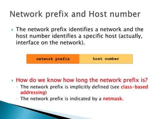
![ IP addresses are written in a so-called dotted
decimal notation
Each byte is identified by a decimal number in
the range [0..255]:
Example:
10000000 10001111 10001001 10010000
1st Byte
= 128
2nd Byte
= 143
3rd Byte
= 137
4th Byte
= 144
128.143.137.144](https://image.slidesharecdn.com/ramakanttyagipresentationonipaddressing-150820162044-lva1-app6892/85/Ramakant-tyagi-presentation-on-ip-addressing-4-320.jpg)


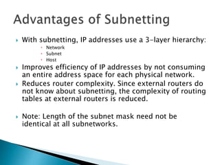
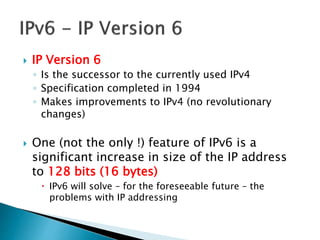
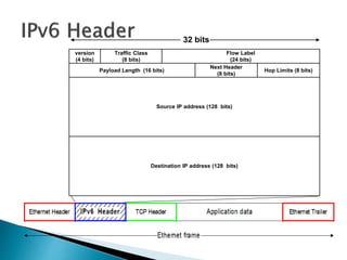
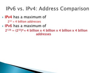


The document discusses IP addressing and IPv6. It defines what an IP address is, how it is written in dotted decimal notation, and its structure including the network prefix and host number. It describes problems with the original IP address classification scheme and how subnetting and CIDR addressed these. It also summarizes IPv6, including its 128-bit address size which vastly increases the available address space compared to IPv4.