SlideShare a Scribd company logo
George Mason University
Quadcopter Dyamics
Dynamic Systems Model and Interactive Control System
George Mason University
Systems Engineering and Operational Research
Fairfax, United States of America
Adnan Khan
Pwint Htwe
Luis Soto
Waqar Chaudhry
Badar Alwetaid
Unmanned aerial vehicles (UAV) have transformed our world
by enabling us to remotely perform actions never before possible.
From military purposes to filmmaking, UAV’s are now even
available to everyday citizens with little oversight. Due to the
increasing use of these machines in industry and now the civilian
sphere, it is in our interest to model their behavior in different
environments and explore their capabilities.
I. INTRODUCTION
The control systems of quadcopters are a major subject of
research as these vehicles find their place in the aerial world.
Their interaction with other aerial and ground-based units
requires us to refine and develop their controls so they maintain
safety standards and better serve our needs.
This report covers an exercise in which a quadcopter was
modeled to follow a user-specified altitude profile which
includes parameters such as payload, desired altitude, desired
ascent and descent speeds, and hover time.
II. MODEL DESCRIPTION AND EQUATIONS
A. Assumptions
The model was simplified in order to place greater
emphasis on user-interaction and system response than
physical quadcopter design parameters. Relationships between
rotor speed, battery life, and lift were not taken into account.
All four rotors are seen to be providing one upward thrust force
which is assumed to be 31.4 Newtons [1]. Note that maximum
thrust is not used in the “Max Thrust” gain as it was not
required to meet system requirements. The unit weight,
dimensions, and temperature range were modeled after the DJI
Phantom 3 professional [2].
Drag force is modeled using an air density value based on a
median temperature of 68°F, a mean national elevation of
2500ft and 50% humidity. Noise blocks were added to both the
position and velocity to simulate atmospheric changes, wind
turbulence and other minor weather behavior. The body was
modeled as a cube and a coefficient value of 0.8 was used [3].
A delay is added after the controller via the “Action Delay”
block which consists of a transfer function. This provides a
one-second delay which models the delay in system response
after the command executes. An altitude sensor is added to
provide a feedback loop allowing the system to conform to the
altitude profile.
Figure 1: Free body diagram (Ascent)
B. Model Description
The free body diagram for the system can be seen in figure
1 above. Individual thrust forces are shown in the diagram on
each rotor (Tx forces were summed into a single upward
thrust) and the downward thrust and weight forces are
represented by a single vector. Only movement in the z-axis is
modeled and the three phases are ascent, descent and hover. In
the hover phase, the drag force is absent and in the descent
phase it faces in the opposite direction (upward). The figure
below shows both of these phases:
Figure 2: Hover (left) and descent (right)
C. Equations
The equation of motion shown on the next page gives the
acceleration of the quadcopter in the z-axis as 𝑧̈. The parameter
T represents thrust which is the control. m represents the mass
of the quadcopter, while mp represents the mass of the payload.
This mass is entered in the MATLAB script file provided with
the simulation as a weight in pounds and exported to the
Simulink diagram. The drag equation complicates the model
George Mason University
due to the 𝑧̇2
term which is not a common Laplace transform.
Laplace-domain analyses such as the final value theorem and
root-locus plots are no longer possible. The reliance then shifts
toward the numerical method provided by Simulink.
𝑧̈ =
𝑇
𝑚 + 𝑚 𝑝
−
9.8(𝑚 + 𝑚 𝑝) + 0.11𝑧̇2
𝑚 + 𝑚 𝑝
Once the altitude profile is added and the feedback loop is run
from the output, the thrust parameter T becomes a gain and is
used to control the system. The implementation can be seen in
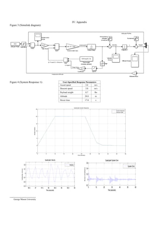
figure 3 of the Appendix where the T parameter is named
“Max thrust”. Note the saturation block added after the altitude
profile. This block serves no other purpose than to filter out all
negative inputs from the altitude profile. The “sign” block
before the squared velocity term allows the system to retain the
negative sign of the velocity despite the term being squared.
III. RESULTS
A. Tables and Figures
The Appendix contains the Simulink diagram for the model
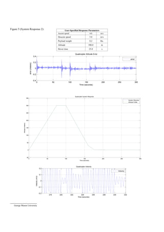
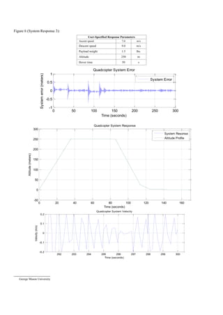
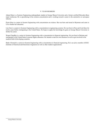
(Figure 3) as well as various plots (Figures 4-6). The noise
function makes the graphs difficult to interpret but this is a
realistic constraint because at only 2.8lbs, the vehicle is fairly
sensitive to wind and other external forces. The tables
accompanying the plots display the inputs entered by the user.
A wide range of values were chosen for each response to
model system behavior at different states. The response
plotted in figure 6 has particularly large values which are
extreme cases designed to test the system at its limits. The DJI
Phantom 3 Professional has maximum ascent and descent
speeds of 5m/s and 3m/s, respectively.
B. Analysis
One system requirements dictates that it must not deviate
from the user-specified altitude profile by more than 1m. The
standard error plot shows the actual altitude subtracted by the
input profile altitude. The scope is connected before the thrust
gain which gives an accurate representation of deviation. In
“System Response 3”, the effect of the large payload of 1.5lbs
(more than half the weight of the vehicle) is evident by the
larger standard error. However, the system still meets the
project specifications with considerable room for error. Due to
the large thrust potential of the rotors, deviation from the
specified profile is quick and enough to keep the quadcopter on
course with great accuracy. It is also less sensitive to higher
payloads and has a high payload capacity. It should be noted
that the error may be caused by large velocity values as well,
since the other two system responses have lower magnitudes of
standard error.
The system meets the landing velocity requirement as well
in every case despite visible oscillation from the noise blocks.
System velocity appears to be much smoother in response 1
which is likely due to the smaller ascent and descent speeds.
Velocity oscillations are also caused by the abrupt changes in
the altitude profile which can be seen in the landing phases of
each system response. Same-size matrices were used to
produce the altitude profile which may not be the best way of
modeling a flight plan. A decaying exponential or another
continuously time-based function may allow for a smoother
landing, especially when the ascent and descent speeds are of
larger magnitude. At t = 10 in the first response plot, the
oscillations caused by the abrupt change in command can be
seen in the velocity plot. The same destabilizing behavior can
be seen in the same plot at approximately t =28, and t = 35. I is
worthy of noting that the abrupt rise in error is more prevalent
at other parts of the graph than the landing phases. System
performance could be utilized further if a smoother altitude
profile was made. A smoother input would cause fewer
oscillations, increase vehicle payload and maximize ascent and
descent speeds.
CONCLUSION
The model shows the potential of the four-rotor quadcopter
to be safe, efficient and extremely useful. The maximum thrust
value used in this model shows that the vehicle can pick up
more than half its weight as a payload and still meet the
required deviation limits. As a general rule, greater payload or
mass seems to require a proportional increase in the maximum
allowable thrust that the rotors produce. The simulation
conducted demonstrates the viability of the quadcopter as a
safe and effective low-cost delivery system. Moreover, the
model can be modified for use with different physical
parameters with ease. In conclusion, this model can be used to
explore the limits of quadcopters as their immense application
potential is explored.
References
[1] E310 - Specs | DJI. (n.d.). Retrieved December 11, 2015, from
http://www.dji.com/product/e310/spec?www=v1
[2] Phantom 3 Professional - Specs, FAQ, Tutorials, Downloads
and DJI GO | DJI. (n.d.). Retrieved December 11, 2015, from
http://www.dji.com/product/phantom-3-pro/info#spec
[3] Drag Coefficient. (n.d.). Retrieved December 11, 2015, from
http://www.engineeringtoolbox.com/drag-coefficient-d_627.html
George Mason University
IV: Appendix
Figure 3 (Simulink diagram):
Figure 4 (System Response 1):
0 5 10 15 20 25 30 35 40 45 50
-5
0
5
10
15
20
25
Time (seconds)
Altitude(meters)
Quadcopter System Response
System Resonse
Altitude Profile
56.5 57 57.5 58 58.5 59 59.5 60
-0.3
-0.2
-0.1
0
0.1
0.2
Time (seconds)
Velocity(m/s)
Quadcopter Velocity
Velocity
0 10 20 30 40 50 60
-0.2
0
0.2
0.4
0.6
Time(seconds)
Error(meters)
QuadcopterSystem Error
System Error
User-Specified Response Parameters
Ascent speed 2.0 m/s
Descent speed 3.0 m/s
Payload weight 0.7 lbs
Altitude 20.0 m
Hover time 17.0 s
George Mason University
Figure 5 (System Response 2):
0 50 100 150 200 250 300
-0.4
-0.2
0
0.2
0.4
Time (seconds)
error(meters)
Quadcopter Altitude Error
error
0 50 100 150 200 250 300
-50
0
50
100
150
200
250
300
350
Time (seconds)
Altitude(meters)
Quadcopter System Response
System Resonse
Altitude Profile
218 220 222 224 226 228 230 232
-0.2
-0.1
0
0.1
0.2
Time (seconds)
Velocity(m/s)
Quadcopter Velocity
Velocity
User-Specified Response Parameters
Ascent speed 4.0 m/s
Descent speed 5.0 m/s
Payload weight 0.2 lbs.
Altitude 300.0 m
Hover time 25.0 s
George Mason University
Figure 6 (System Response 3):
0 50 100 150 200 250 300
-1
-0.5
0
0.5
1
Time (seconds)
Systemerror(meters)
Quadcopter System Error
System Error
0 20 40 60 80 100 120 140 160
-50
0
50
100
150
200
250
300
Time (seconds)
Altitude(meters)
Quadcopter System Response
System Resonse
Altitude Profile
292 293 294 295 296 297 298 299 300
-0.2
-0.1
0
0.1
0.2
Time (seconds)
Velocity(m/s)
Quadcopter System Velocity
User-Specified Response Parameters
Ascent speed 7.0 m/s
Descent speed 9.0 m/s
Payload weight 1.5 lbs.
Altitude 250 m
Hover time 50 s
George Mason University
V: TEAM MEMBERS
Adnan Khan is a Systems Engineering undergraduate student at George Mason University and a former certified Mercedes-Benz
repair technician. He is specializing in the aviation concentration and is working toward a career in the automotive or aerospace
industry.
Pwint Htwe is a junior in System Engineering with concentration on aviation. She was born and raised in Myanmar and came to
US to further her education.
Luis Soto is a junior in Systems Engineering with a concentration in engineering systems. He was born in Peru and lived there for
twelve years before immigrating to the United States. He hopes to apply the knowledge he gains at George Mason University to
further his career.
Waqar Chaudhry is a senior in Systems Engineering with a concentration in financial engineering. He was born in Pakistan and
immigrated to the United States to pursue higher education. He intends to start his own business as well as get involved in the
medical field of developing countries.
Bader Alwetaid is a senior in Systems Engineering with a concentration in financial engineering. He is an active member of IEEE
(Institute of Electrical and Electronics Engineers) as well as other student organizations.

More Related Content

What's hot

Qaudcopters
QaudcoptersQaudcopters
Qaudcopters
SHREYANSH VATS
 
Tricopter -design and its fabrication
Tricopter -design and its fabricationTricopter -design and its fabrication
Tricopter -design and its fabrication
Chintala Harthik
 
Making of Drone
Making of  DroneMaking of  Drone
Making of Drone
mohanchandrakanth swarna
 
study of yaw and pitch control in quad copter
study  of yaw and pitch  control in quad copter study  of yaw and pitch  control in quad copter
study of yaw and pitch control in quad copter
PranaliPatil76
 
Quadcopter
QuadcopterQuadcopter
Quadcopter
Aakash Goyal
 
Construction of Quadcopter
Construction of QuadcopterConstruction of Quadcopter
Construction of Quadcopter
Michael Bseliss
 
Unmanned Aerial Vehicle for Surveillance
Unmanned Aerial Vehicle for Surveillance Unmanned Aerial Vehicle for Surveillance
Unmanned Aerial Vehicle for Surveillance
Vedant Srivastava
 
QUAD COPTERS FULL PPT
QUAD COPTERS FULL PPTQUAD COPTERS FULL PPT
QUAD COPTERS FULL PPT
Girija Sankar Dash
 
Final Year Project report on quadcopter
Final Year Project report on quadcopter Final Year Project report on quadcopter
Final Year Project report on quadcopter
Er. Ashutosh Mishra
 
Quadcopter 140410021020-phpapp02
Quadcopter 140410021020-phpapp02Quadcopter 140410021020-phpapp02
Quadcopter 140410021020-phpapp02
Prasanth Reddy
 
Quadcopter Design for Payload Delivery
Quadcopter Design for Payload Delivery Quadcopter Design for Payload Delivery
Quadcopter Design for Payload Delivery
Onyebuchi nosiri
 
Quadcopter Design for Payload Delivery
Quadcopter Design for Payload Delivery Quadcopter Design for Payload Delivery
Quadcopter Design for Payload Delivery
Onyebuchi nosiri
 
Quadcopter
QuadcopterQuadcopter
Quadcopter
sunny4992
 
UAV Building a quadcopter project
UAV Building a quadcopter projectUAV Building a quadcopter project
UAV Building a quadcopter project
hossam gouda
 
PID vs LQR controller for tilt rotor airplane
PID vs LQR controller for tilt rotor airplane PID vs LQR controller for tilt rotor airplane
PID vs LQR controller for tilt rotor airplane
IJECEIAES
 
introduction to quadcopter
introduction to quadcopter introduction to quadcopter
introduction to quadcopter
mohamed rameez
 
Report of quadcopter
Report of quadcopterReport of quadcopter
Report of quadcopter
Ashish Patel
 
Helicopter With Gps
Helicopter With GpsHelicopter With Gps
Helicopter With Gps
esthershiang88
 
Physical Flying Agents: Ummanned Aerial Vehicles Control, Coordination and Em...
Physical Flying Agents: Ummanned Aerial Vehicles Control, Coordination and Em...Physical Flying Agents: Ummanned Aerial Vehicles Control, Coordination and Em...
Physical Flying Agents: Ummanned Aerial Vehicles Control, Coordination and Em...
Corrado Santoro
 

What's hot (20)

Qaudcopters
QaudcoptersQaudcopters
Qaudcopters
 
Tricopter -design and its fabrication
Tricopter -design and its fabricationTricopter -design and its fabrication
Tricopter -design and its fabrication
 
Making of Drone
Making of  DroneMaking of  Drone
Making of Drone
 
study of yaw and pitch control in quad copter
study  of yaw and pitch  control in quad copter study  of yaw and pitch  control in quad copter
study of yaw and pitch control in quad copter
 
Quadcopter
QuadcopterQuadcopter
Quadcopter
 
Construction of Quadcopter
Construction of QuadcopterConstruction of Quadcopter
Construction of Quadcopter
 
Unmanned Aerial Vehicle for Surveillance
Unmanned Aerial Vehicle for Surveillance Unmanned Aerial Vehicle for Surveillance
Unmanned Aerial Vehicle for Surveillance
 
QUAD COPTERS FULL PPT
QUAD COPTERS FULL PPTQUAD COPTERS FULL PPT
QUAD COPTERS FULL PPT
 
Final Year Project report on quadcopter
Final Year Project report on quadcopter Final Year Project report on quadcopter
Final Year Project report on quadcopter
 
Quadcopter 140410021020-phpapp02
Quadcopter 140410021020-phpapp02Quadcopter 140410021020-phpapp02
Quadcopter 140410021020-phpapp02
 
Quadcopter Design for Payload Delivery
Quadcopter Design for Payload Delivery Quadcopter Design for Payload Delivery
Quadcopter Design for Payload Delivery
 
Quadcopter Design for Payload Delivery
Quadcopter Design for Payload Delivery Quadcopter Design for Payload Delivery
Quadcopter Design for Payload Delivery
 
Quadcopter
QuadcopterQuadcopter
Quadcopter
 
UAV Building a quadcopter project
UAV Building a quadcopter projectUAV Building a quadcopter project
UAV Building a quadcopter project
 
PID vs LQR controller for tilt rotor airplane
PID vs LQR controller for tilt rotor airplane PID vs LQR controller for tilt rotor airplane
PID vs LQR controller for tilt rotor airplane
 
introduction to quadcopter
introduction to quadcopter introduction to quadcopter
introduction to quadcopter
 
Final
FinalFinal
Final
 
Report of quadcopter
Report of quadcopterReport of quadcopter
Report of quadcopter
 
Helicopter With Gps
Helicopter With GpsHelicopter With Gps
Helicopter With Gps
 
Physical Flying Agents: Ummanned Aerial Vehicles Control, Coordination and Em...
Physical Flying Agents: Ummanned Aerial Vehicles Control, Coordination and Em...Physical Flying Agents: Ummanned Aerial Vehicles Control, Coordination and Em...
Physical Flying Agents: Ummanned Aerial Vehicles Control, Coordination and Em...
 

Viewers also liked

Senior Design Final Report
Senior Design Final ReportSenior Design Final Report
Senior Design Final Report
Tyler Akira Smolen
 
Prototype5 report
Prototype5 reportPrototype5 report
Prototype5 report
Tyler Akira Smolen
 
Project Summary Team A
Project Summary Team AProject Summary Team A
Project Summary Team AHuda Sedaki
 
Modeling and control approach to a distinctive quadrotor helicopter
Modeling and control approach to a distinctive quadrotor helicopterModeling and control approach to a distinctive quadrotor helicopter
Modeling and control approach to a distinctive quadrotor helicopter
ISA Interchange
 
Quadrotor Control: Autopilot
Quadrotor Control: AutopilotQuadrotor Control: Autopilot
Quadrotor Control: Autopilotadas2327
 
Modeling and Roll, Pitch and Yaw Simulation of Quadrotor.
Modeling and Roll, Pitch and Yaw Simulation of Quadrotor.Modeling and Roll, Pitch and Yaw Simulation of Quadrotor.
Modeling and Roll, Pitch and Yaw Simulation of Quadrotor.
Oka Danil
 
Design and Implementation of a Quadrotor Helicopter
Design and Implementation of a Quadrotor HelicopterDesign and Implementation of a Quadrotor Helicopter
Design and Implementation of a Quadrotor Helicopter
Hicham Berkouk
 
Quadcopter Technology
Quadcopter TechnologyQuadcopter Technology
Quadcopter Technology
Michael Bseliss
 

Viewers also liked (9)

quadcopter
quadcopterquadcopter
quadcopter
 
Senior Design Final Report
Senior Design Final ReportSenior Design Final Report
Senior Design Final Report
 
Prototype5 report
Prototype5 reportPrototype5 report
Prototype5 report
 
Project Summary Team A
Project Summary Team AProject Summary Team A
Project Summary Team A
 
Modeling and control approach to a distinctive quadrotor helicopter
Modeling and control approach to a distinctive quadrotor helicopterModeling and control approach to a distinctive quadrotor helicopter
Modeling and control approach to a distinctive quadrotor helicopter
 
Quadrotor Control: Autopilot
Quadrotor Control: AutopilotQuadrotor Control: Autopilot
Quadrotor Control: Autopilot
 
Modeling and Roll, Pitch and Yaw Simulation of Quadrotor.
Modeling and Roll, Pitch and Yaw Simulation of Quadrotor.Modeling and Roll, Pitch and Yaw Simulation of Quadrotor.
Modeling and Roll, Pitch and Yaw Simulation of Quadrotor.
 
Design and Implementation of a Quadrotor Helicopter
Design and Implementation of a Quadrotor HelicopterDesign and Implementation of a Quadrotor Helicopter
Design and Implementation of a Quadrotor Helicopter
 
Quadcopter Technology
Quadcopter TechnologyQuadcopter Technology
Quadcopter Technology
 

Similar to Quadcopter Simulation

B045012015
B045012015B045012015
B045012015
researchinventy
 
IRJET- A Performance of Hybrid Control in Nonlinear Dynamic Multirotor UAV
IRJET- A Performance of Hybrid Control in Nonlinear Dynamic Multirotor UAVIRJET- A Performance of Hybrid Control in Nonlinear Dynamic Multirotor UAV
IRJET- A Performance of Hybrid Control in Nonlinear Dynamic Multirotor UAV
IRJET Journal
 
CONCEPT OF OPERATIONS TO SYSTEM DESIGN AND DEVELOPMENT-AN INTEGRATED SYSTEM F...
CONCEPT OF OPERATIONS TO SYSTEM DESIGN AND DEVELOPMENT-AN INTEGRATED SYSTEM F...CONCEPT OF OPERATIONS TO SYSTEM DESIGN AND DEVELOPMENT-AN INTEGRATED SYSTEM F...
CONCEPT OF OPERATIONS TO SYSTEM DESIGN AND DEVELOPMENT-AN INTEGRATED SYSTEM F...
ijics
 
CONCEPT OF OPERATIONS TO SYSTEM DESIGN AND DEVELOPMENT-AN INTEGRATED SYSTEM F...
CONCEPT OF OPERATIONS TO SYSTEM DESIGN AND DEVELOPMENT-AN INTEGRATED SYSTEM F...CONCEPT OF OPERATIONS TO SYSTEM DESIGN AND DEVELOPMENT-AN INTEGRATED SYSTEM F...
CONCEPT OF OPERATIONS TO SYSTEM DESIGN AND DEVELOPMENT-AN INTEGRATED SYSTEM F...
ijcisjournal
 
The research of 6-DOF flight simulator washout filter Control Method
The research of 6-DOF flight simulator washout filter Control MethodThe research of 6-DOF flight simulator washout filter Control Method
The research of 6-DOF flight simulator washout filter Control Method
IJRES Journal
 
Triton UAS Technical Design Paper 2020-2021
Triton UAS Technical Design Paper 2020-2021Triton UAS Technical Design Paper 2020-2021
Triton UAS Technical Design Paper 2020-2021
KennyPham19
 
Optimal and pid controller for controlling camera’s position in unmanned aeri...
Optimal and pid controller for controlling camera’s position in unmanned aeri...Optimal and pid controller for controlling camera’s position in unmanned aeri...
Optimal and pid controller for controlling camera’s position in unmanned aeri...
Zac Darcy
 
Optimal and Pid Controller for Controlling Camera's Position InUnmanned Aeria...
Optimal and Pid Controller for Controlling Camera's Position InUnmanned Aeria...Optimal and Pid Controller for Controlling Camera's Position InUnmanned Aeria...
Optimal and Pid Controller for Controlling Camera's Position InUnmanned Aeria...
Zac Darcy
 
Adaptive control of nonlinear system based on QFT application to 3-DOF flight...
Adaptive control of nonlinear system based on QFT application to 3-DOF flight...Adaptive control of nonlinear system based on QFT application to 3-DOF flight...
Adaptive control of nonlinear system based on QFT application to 3-DOF flight...
TELKOMNIKA JOURNAL
 
Development and Implementation of a Washout Algorithm for a 6-dof Motion Plat...
Development and Implementation of a Washout Algorithm for a 6-dof Motion Plat...Development and Implementation of a Washout Algorithm for a 6-dof Motion Plat...
Development and Implementation of a Washout Algorithm for a 6-dof Motion Plat...
IJRES Journal
 
Improvement of Pitch Motion Control of an Aircraft Systems
Improvement of Pitch Motion Control of an Aircraft SystemsImprovement of Pitch Motion Control of an Aircraft Systems
Improvement of Pitch Motion Control of an Aircraft Systems
TELKOMNIKA JOURNAL
 
CRASH AVOIDANCE SYSTEM FOR DRONES
CRASH AVOIDANCE SYSTEM FOR DRONESCRASH AVOIDANCE SYSTEM FOR DRONES
CRASH AVOIDANCE SYSTEM FOR DRONES
IRJET Journal
 
Automation of Air Traffic Management Using Fuzzy Logic Algorithm to Integrate...
Automation of Air Traffic Management Using Fuzzy Logic Algorithm to Integrate...Automation of Air Traffic Management Using Fuzzy Logic Algorithm to Integrate...
Automation of Air Traffic Management Using Fuzzy Logic Algorithm to Integrate...
IJECEIAES
 
An Unmanned Rotorcraft System with Embedded Design
An Unmanned Rotorcraft System with Embedded DesignAn Unmanned Rotorcraft System with Embedded Design
An Unmanned Rotorcraft System with Embedded Design
IOSR Journals
 
E011133663
E011133663E011133663
E011133663
IOSR Journals
 
IRJET- Quadrotor Modeling and Control using PID Technique
IRJET- Quadrotor Modeling and Control using PID TechniqueIRJET- Quadrotor Modeling and Control using PID Technique
IRJET- Quadrotor Modeling and Control using PID Technique
IRJET Journal
 
Visualizing the Flight Test Data and its Simulation
Visualizing the Flight Test Data and its SimulationVisualizing the Flight Test Data and its Simulation
Visualizing the Flight Test Data and its Simulation
IRJET Journal
 
IRJET - Design and Computational Fluid Dynamic Simulation of Micro Air Ve...
IRJET -  	  Design and Computational Fluid Dynamic Simulation of Micro Air Ve...IRJET -  	  Design and Computational Fluid Dynamic Simulation of Micro Air Ve...
IRJET - Design and Computational Fluid Dynamic Simulation of Micro Air Ve...
IRJET Journal
 
Stability Control of an Autonomous Quadcopter through PID Control Law
Stability Control of an Autonomous Quadcopter through PID Control LawStability Control of an Autonomous Quadcopter through PID Control Law
Stability Control of an Autonomous Quadcopter through PID Control Law
IJERA Editor
 

Similar to Quadcopter Simulation (20)

B045012015
B045012015B045012015
B045012015
 
IRJET- A Performance of Hybrid Control in Nonlinear Dynamic Multirotor UAV
IRJET- A Performance of Hybrid Control in Nonlinear Dynamic Multirotor UAVIRJET- A Performance of Hybrid Control in Nonlinear Dynamic Multirotor UAV
IRJET- A Performance of Hybrid Control in Nonlinear Dynamic Multirotor UAV
 
CONCEPT OF OPERATIONS TO SYSTEM DESIGN AND DEVELOPMENT-AN INTEGRATED SYSTEM F...
CONCEPT OF OPERATIONS TO SYSTEM DESIGN AND DEVELOPMENT-AN INTEGRATED SYSTEM F...CONCEPT OF OPERATIONS TO SYSTEM DESIGN AND DEVELOPMENT-AN INTEGRATED SYSTEM F...
CONCEPT OF OPERATIONS TO SYSTEM DESIGN AND DEVELOPMENT-AN INTEGRATED SYSTEM F...
 
CONCEPT OF OPERATIONS TO SYSTEM DESIGN AND DEVELOPMENT-AN INTEGRATED SYSTEM F...
CONCEPT OF OPERATIONS TO SYSTEM DESIGN AND DEVELOPMENT-AN INTEGRATED SYSTEM F...CONCEPT OF OPERATIONS TO SYSTEM DESIGN AND DEVELOPMENT-AN INTEGRATED SYSTEM F...
CONCEPT OF OPERATIONS TO SYSTEM DESIGN AND DEVELOPMENT-AN INTEGRATED SYSTEM F...
 
The research of 6-DOF flight simulator washout filter Control Method
The research of 6-DOF flight simulator washout filter Control MethodThe research of 6-DOF flight simulator washout filter Control Method
The research of 6-DOF flight simulator washout filter Control Method
 
Triton UAS Technical Design Paper 2020-2021
Triton UAS Technical Design Paper 2020-2021Triton UAS Technical Design Paper 2020-2021
Triton UAS Technical Design Paper 2020-2021
 
Optimal and pid controller for controlling camera’s position in unmanned aeri...
Optimal and pid controller for controlling camera’s position in unmanned aeri...Optimal and pid controller for controlling camera’s position in unmanned aeri...
Optimal and pid controller for controlling camera’s position in unmanned aeri...
 
Optimal and Pid Controller for Controlling Camera's Position InUnmanned Aeria...
Optimal and Pid Controller for Controlling Camera's Position InUnmanned Aeria...Optimal and Pid Controller for Controlling Camera's Position InUnmanned Aeria...
Optimal and Pid Controller for Controlling Camera's Position InUnmanned Aeria...
 
Adaptive control of nonlinear system based on QFT application to 3-DOF flight...
Adaptive control of nonlinear system based on QFT application to 3-DOF flight...Adaptive control of nonlinear system based on QFT application to 3-DOF flight...
Adaptive control of nonlinear system based on QFT application to 3-DOF flight...
 
Development and Implementation of a Washout Algorithm for a 6-dof Motion Plat...
Development and Implementation of a Washout Algorithm for a 6-dof Motion Plat...Development and Implementation of a Washout Algorithm for a 6-dof Motion Plat...
Development and Implementation of a Washout Algorithm for a 6-dof Motion Plat...
 
Improvement of Pitch Motion Control of an Aircraft Systems
Improvement of Pitch Motion Control of an Aircraft SystemsImprovement of Pitch Motion Control of an Aircraft Systems
Improvement of Pitch Motion Control of an Aircraft Systems
 
CRASH AVOIDANCE SYSTEM FOR DRONES
CRASH AVOIDANCE SYSTEM FOR DRONESCRASH AVOIDANCE SYSTEM FOR DRONES
CRASH AVOIDANCE SYSTEM FOR DRONES
 
30720130101005
3072013010100530720130101005
30720130101005
 
Automation of Air Traffic Management Using Fuzzy Logic Algorithm to Integrate...
Automation of Air Traffic Management Using Fuzzy Logic Algorithm to Integrate...Automation of Air Traffic Management Using Fuzzy Logic Algorithm to Integrate...
Automation of Air Traffic Management Using Fuzzy Logic Algorithm to Integrate...
 
An Unmanned Rotorcraft System with Embedded Design
An Unmanned Rotorcraft System with Embedded DesignAn Unmanned Rotorcraft System with Embedded Design
An Unmanned Rotorcraft System with Embedded Design
 
E011133663
E011133663E011133663
E011133663
 
IRJET- Quadrotor Modeling and Control using PID Technique
IRJET- Quadrotor Modeling and Control using PID TechniqueIRJET- Quadrotor Modeling and Control using PID Technique
IRJET- Quadrotor Modeling and Control using PID Technique
 
Visualizing the Flight Test Data and its Simulation
Visualizing the Flight Test Data and its SimulationVisualizing the Flight Test Data and its Simulation
Visualizing the Flight Test Data and its Simulation
 
IRJET - Design and Computational Fluid Dynamic Simulation of Micro Air Ve...
IRJET -  	  Design and Computational Fluid Dynamic Simulation of Micro Air Ve...IRJET -  	  Design and Computational Fluid Dynamic Simulation of Micro Air Ve...
IRJET - Design and Computational Fluid Dynamic Simulation of Micro Air Ve...
 
Stability Control of an Autonomous Quadcopter through PID Control Law
Stability Control of an Autonomous Quadcopter through PID Control LawStability Control of an Autonomous Quadcopter through PID Control Law
Stability Control of an Autonomous Quadcopter through PID Control Law
 

More from Adnan Khan

Khan_Transcript_Unofficial
Khan_Transcript_UnofficialKhan_Transcript_Unofficial
Khan_Transcript_UnofficialAdnan Khan
 
SYST335FinalReportUpdated.docx
SYST335FinalReportUpdated.docxSYST335FinalReportUpdated.docx
SYST335FinalReportUpdated.docxAdnan Khan
 
Literature_Review_Khan_Adnan
Literature_Review_Khan_AdnanLiterature_Review_Khan_Adnan
Literature_Review_Khan_AdnanAdnan Khan
 
NOVA Transcript unofficial
NOVA Transcript unofficialNOVA Transcript unofficial
NOVA Transcript unofficialAdnan Khan
 
220 PROJECT 2015 (2)
220 PROJECT 2015 (2)220 PROJECT 2015 (2)
220 PROJECT 2015 (2)Adnan Khan
 

More from Adnan Khan (7)

Khan_Transcript_Unofficial
Khan_Transcript_UnofficialKhan_Transcript_Unofficial
Khan_Transcript_Unofficial
 
SYST335FinalReportUpdated.docx
SYST335FinalReportUpdated.docxSYST335FinalReportUpdated.docx
SYST335FinalReportUpdated.docx
 
Literature_Review_Khan_Adnan
Literature_Review_Khan_AdnanLiterature_Review_Khan_Adnan
Literature_Review_Khan_Adnan
 
NOVA Transcript unofficial
NOVA Transcript unofficialNOVA Transcript unofficial
NOVA Transcript unofficial
 
PRESENTATION
PRESENTATIONPRESENTATION
PRESENTATION
 
Fusion
FusionFusion
Fusion
 
220 PROJECT 2015 (2)
220 PROJECT 2015 (2)220 PROJECT 2015 (2)
220 PROJECT 2015 (2)
 

Quadcopter Simulation

  • 1. George Mason University Quadcopter Dyamics Dynamic Systems Model and Interactive Control System George Mason University Systems Engineering and Operational Research Fairfax, United States of America Adnan Khan Pwint Htwe Luis Soto Waqar Chaudhry Badar Alwetaid Unmanned aerial vehicles (UAV) have transformed our world by enabling us to remotely perform actions never before possible. From military purposes to filmmaking, UAV’s are now even available to everyday citizens with little oversight. Due to the increasing use of these machines in industry and now the civilian sphere, it is in our interest to model their behavior in different environments and explore their capabilities. I. INTRODUCTION The control systems of quadcopters are a major subject of research as these vehicles find their place in the aerial world. Their interaction with other aerial and ground-based units requires us to refine and develop their controls so they maintain safety standards and better serve our needs. This report covers an exercise in which a quadcopter was modeled to follow a user-specified altitude profile which includes parameters such as payload, desired altitude, desired ascent and descent speeds, and hover time. II. MODEL DESCRIPTION AND EQUATIONS A. Assumptions The model was simplified in order to place greater emphasis on user-interaction and system response than physical quadcopter design parameters. Relationships between rotor speed, battery life, and lift were not taken into account. All four rotors are seen to be providing one upward thrust force which is assumed to be 31.4 Newtons [1]. Note that maximum thrust is not used in the “Max Thrust” gain as it was not required to meet system requirements. The unit weight, dimensions, and temperature range were modeled after the DJI Phantom 3 professional [2]. Drag force is modeled using an air density value based on a median temperature of 68°F, a mean national elevation of 2500ft and 50% humidity. Noise blocks were added to both the position and velocity to simulate atmospheric changes, wind turbulence and other minor weather behavior. The body was modeled as a cube and a coefficient value of 0.8 was used [3]. A delay is added after the controller via the “Action Delay” block which consists of a transfer function. This provides a one-second delay which models the delay in system response after the command executes. An altitude sensor is added to provide a feedback loop allowing the system to conform to the altitude profile. Figure 1: Free body diagram (Ascent) B. Model Description The free body diagram for the system can be seen in figure 1 above. Individual thrust forces are shown in the diagram on each rotor (Tx forces were summed into a single upward thrust) and the downward thrust and weight forces are represented by a single vector. Only movement in the z-axis is modeled and the three phases are ascent, descent and hover. In the hover phase, the drag force is absent and in the descent phase it faces in the opposite direction (upward). The figure below shows both of these phases: Figure 2: Hover (left) and descent (right) C. Equations The equation of motion shown on the next page gives the acceleration of the quadcopter in the z-axis as 𝑧̈. The parameter T represents thrust which is the control. m represents the mass of the quadcopter, while mp represents the mass of the payload. This mass is entered in the MATLAB script file provided with the simulation as a weight in pounds and exported to the Simulink diagram. The drag equation complicates the model
  • 2. George Mason University due to the 𝑧̇2 term which is not a common Laplace transform. Laplace-domain analyses such as the final value theorem and root-locus plots are no longer possible. The reliance then shifts toward the numerical method provided by Simulink. 𝑧̈ = 𝑇 𝑚 + 𝑚 𝑝 − 9.8(𝑚 + 𝑚 𝑝) + 0.11𝑧̇2 𝑚 + 𝑚 𝑝 Once the altitude profile is added and the feedback loop is run from the output, the thrust parameter T becomes a gain and is used to control the system. The implementation can be seen in figure 3 of the Appendix where the T parameter is named “Max thrust”. Note the saturation block added after the altitude profile. This block serves no other purpose than to filter out all negative inputs from the altitude profile. The “sign” block before the squared velocity term allows the system to retain the negative sign of the velocity despite the term being squared. III. RESULTS A. Tables and Figures The Appendix contains the Simulink diagram for the model (Figure 3) as well as various plots (Figures 4-6). The noise function makes the graphs difficult to interpret but this is a realistic constraint because at only 2.8lbs, the vehicle is fairly sensitive to wind and other external forces. The tables accompanying the plots display the inputs entered by the user. A wide range of values were chosen for each response to model system behavior at different states. The response plotted in figure 6 has particularly large values which are extreme cases designed to test the system at its limits. The DJI Phantom 3 Professional has maximum ascent and descent speeds of 5m/s and 3m/s, respectively. B. Analysis One system requirements dictates that it must not deviate from the user-specified altitude profile by more than 1m. The standard error plot shows the actual altitude subtracted by the input profile altitude. The scope is connected before the thrust gain which gives an accurate representation of deviation. In “System Response 3”, the effect of the large payload of 1.5lbs (more than half the weight of the vehicle) is evident by the larger standard error. However, the system still meets the project specifications with considerable room for error. Due to the large thrust potential of the rotors, deviation from the specified profile is quick and enough to keep the quadcopter on course with great accuracy. It is also less sensitive to higher payloads and has a high payload capacity. It should be noted that the error may be caused by large velocity values as well, since the other two system responses have lower magnitudes of standard error. The system meets the landing velocity requirement as well in every case despite visible oscillation from the noise blocks. System velocity appears to be much smoother in response 1 which is likely due to the smaller ascent and descent speeds. Velocity oscillations are also caused by the abrupt changes in the altitude profile which can be seen in the landing phases of each system response. Same-size matrices were used to produce the altitude profile which may not be the best way of modeling a flight plan. A decaying exponential or another continuously time-based function may allow for a smoother landing, especially when the ascent and descent speeds are of larger magnitude. At t = 10 in the first response plot, the oscillations caused by the abrupt change in command can be seen in the velocity plot. The same destabilizing behavior can be seen in the same plot at approximately t =28, and t = 35. I is worthy of noting that the abrupt rise in error is more prevalent at other parts of the graph than the landing phases. System performance could be utilized further if a smoother altitude profile was made. A smoother input would cause fewer oscillations, increase vehicle payload and maximize ascent and descent speeds. CONCLUSION The model shows the potential of the four-rotor quadcopter to be safe, efficient and extremely useful. The maximum thrust value used in this model shows that the vehicle can pick up more than half its weight as a payload and still meet the required deviation limits. As a general rule, greater payload or mass seems to require a proportional increase in the maximum allowable thrust that the rotors produce. The simulation conducted demonstrates the viability of the quadcopter as a safe and effective low-cost delivery system. Moreover, the model can be modified for use with different physical parameters with ease. In conclusion, this model can be used to explore the limits of quadcopters as their immense application potential is explored. References [1] E310 - Specs | DJI. (n.d.). Retrieved December 11, 2015, from http://www.dji.com/product/e310/spec?www=v1 [2] Phantom 3 Professional - Specs, FAQ, Tutorials, Downloads and DJI GO | DJI. (n.d.). Retrieved December 11, 2015, from http://www.dji.com/product/phantom-3-pro/info#spec [3] Drag Coefficient. (n.d.). Retrieved December 11, 2015, from http://www.engineeringtoolbox.com/drag-coefficient-d_627.html
  • 3. George Mason University IV: Appendix Figure 3 (Simulink diagram): Figure 4 (System Response 1): 0 5 10 15 20 25 30 35 40 45 50 -5 0 5 10 15 20 25 Time (seconds) Altitude(meters) Quadcopter System Response System Resonse Altitude Profile 56.5 57 57.5 58 58.5 59 59.5 60 -0.3 -0.2 -0.1 0 0.1 0.2 Time (seconds) Velocity(m/s) Quadcopter Velocity Velocity 0 10 20 30 40 50 60 -0.2 0 0.2 0.4 0.6 Time(seconds) Error(meters) QuadcopterSystem Error System Error User-Specified Response Parameters Ascent speed 2.0 m/s Descent speed 3.0 m/s Payload weight 0.7 lbs Altitude 20.0 m Hover time 17.0 s
  • 4. George Mason University Figure 5 (System Response 2): 0 50 100 150 200 250 300 -0.4 -0.2 0 0.2 0.4 Time (seconds) error(meters) Quadcopter Altitude Error error 0 50 100 150 200 250 300 -50 0 50 100 150 200 250 300 350 Time (seconds) Altitude(meters) Quadcopter System Response System Resonse Altitude Profile 218 220 222 224 226 228 230 232 -0.2 -0.1 0 0.1 0.2 Time (seconds) Velocity(m/s) Quadcopter Velocity Velocity User-Specified Response Parameters Ascent speed 4.0 m/s Descent speed 5.0 m/s Payload weight 0.2 lbs. Altitude 300.0 m Hover time 25.0 s
  • 5. George Mason University Figure 6 (System Response 3): 0 50 100 150 200 250 300 -1 -0.5 0 0.5 1 Time (seconds) Systemerror(meters) Quadcopter System Error System Error 0 20 40 60 80 100 120 140 160 -50 0 50 100 150 200 250 300 Time (seconds) Altitude(meters) Quadcopter System Response System Resonse Altitude Profile 292 293 294 295 296 297 298 299 300 -0.2 -0.1 0 0.1 0.2 Time (seconds) Velocity(m/s) Quadcopter System Velocity User-Specified Response Parameters Ascent speed 7.0 m/s Descent speed 9.0 m/s Payload weight 1.5 lbs. Altitude 250 m Hover time 50 s
  • 6. George Mason University V: TEAM MEMBERS Adnan Khan is a Systems Engineering undergraduate student at George Mason University and a former certified Mercedes-Benz repair technician. He is specializing in the aviation concentration and is working toward a career in the automotive or aerospace industry. Pwint Htwe is a junior in System Engineering with concentration on aviation. She was born and raised in Myanmar and came to US to further her education. Luis Soto is a junior in Systems Engineering with a concentration in engineering systems. He was born in Peru and lived there for twelve years before immigrating to the United States. He hopes to apply the knowledge he gains at George Mason University to further his career. Waqar Chaudhry is a senior in Systems Engineering with a concentration in financial engineering. He was born in Pakistan and immigrated to the United States to pursue higher education. He intends to start his own business as well as get involved in the medical field of developing countries. Bader Alwetaid is a senior in Systems Engineering with a concentration in financial engineering. He is an active member of IEEE (Institute of Electrical and Electronics Engineers) as well as other student organizations.