This document summarizes and compares PID and LQR control strategies for controlling the maneuvers of a tilt rotor airplane. Multiple attitude and altitude PID controllers were used to control a simplified linear model, but this did not account for all coupling between degrees of freedom. An LQR controller was also adopted to provide a more feasible solution for complex maneuvering, though both controllers require linearization of the model. The mathematical modeling section describes the rigid body equations of motion for the tri-tilt rotor configuration in body and earth frames using Newton-Euler formalism. Control of attitudes, positions and transitions between helicopter and airplane modes are discussed.
![International Journal of Electrical and Computer Engineering (IJECE)
Vol. 10, No. 6, December 2020, pp. 6309~6318
ISSN: 2088-8708, DOI: 10.11591/ijece.v10i6.pp6309-6318 6309
Journal homepage: http://ijece.iaescore.com/index.php/IJECE
PID vs LQR controller for tilt rotor airplane
Aoued Houari1
, Imine Bachir2
, Della Krachai Mohamed3
, Mohamed Kara Mohamed4
1
Department of Electronics, University of Sciences and Technology of Oran MB, Algeria
2
Department of Mecanical Engineering, University of Sciences and Technology of Oran MB, Algeria
3
Department of AutomaticEngineering, University of Sciences and Technology of Oran MB, Algeria
4
Department of Maritime and Mechanical Engineering, Liverpool John Moore’s University, United Kingdom
Article Info ABSTRACT
Article history:
Received Dec 30, 2019
Revised May 20, 2020
Accepted Jun 1, 2020
The main thematic of this paper is controlling the main manoeuvers of a tilt
rotor UAV airplane in several modes such as vertical takeoff and landing,
longitudinal translation and the most important phase which deal with
the transition from the helicopter mode to the airplane mode and visversa
based on a new actuators combination technique for specially the yaw motion
with not referring to rotor speed control strategy which is used in controlling
the attitude of a huge number of vehicles nowadays. This new actuator
combination is inspired from that the transient response of a trirotor using
tilting motion dynamics provides a faster response than using rotor speed
dynamics. In the literature, a lot of control technics are used for stabilizing
and guarantee the necessary manoeuvers for executing such task, a multiple
Attitude and Altitude PID controllers were chosen for a simple linear model
of our tilt rotor airplane in order to fulfill the desired trajectory, for reasons of
complexity of our model the multiple PID controller doesnt take into
consideration all the coupling that exists between the degrees of freedom in
our model, so an LQR controller is adopted for more feasible solution of
complex manoeuvering, the both controllers need linearization of the model
for an easy implementation.
Keywords:
Airplane
LQR control
PID control
Tilt rotor
Transition
UAV
VTOL
Copyright © 2020 Institute of Advanced Engineering and Science.
All rights reserved.
Corresponding Author:
Aoued Houari,
Aeronautics and Propulsive Systems Laboratory,
University of Science and Technology of Oran-MB,
B. P 1505, ElMnaouer, Oran-ALgeria.
Email : houari.aoued@univ-usto.dz
1. INTRODUCTION
Several applications are performed nowadays by using UAVs such as rescue operations, detection
and surveillance. Many UAVs configurations are established in order to ensure some objectives like
trajectory planification discussed in [1]. In this paper is studied to find an optimal trajectory tracking control
of a tri tilt-rotor using an LQR controller. A new model or mathematical presentation for controlling a tilt
rotor is the aim subject in [2]. A reconfigurable tri tilt rotor UAV is designed in [3] for autonomous transition
between the VTOL and the fixed wing flight modes by employing the direct longitudinal actuation
techniques. In [4] a development of a quad rotor having a tilt wing mechanism using an LQR and sliding
mode controller for settling the attitude and the altitude are presented via simulations. A proposed designs
in [5] incorporates advantageous structural features which enhances the maneuverability of the rotorcraft,
some new technics are developed specially for hovering control such a nonlinear state feedback controller
which is proved by numerical simulations in [6], thrust vectoring technique with the highest level of
flexibility, maneuverability and minimum requirement of power is discussed in [7], using a backstepping
technique to achieve mode transition control of the aircraft was the subject of [8] for the ability of high speed
forward flight. Other paper researches are dealed with experimental implementation of control technics that](https://image.slidesharecdn.com/22218331jun20may30dec19y-201223022759/85/PID-vs-LQR-controller-for-tilt-rotor-airplane-1-320.jpg)
![International Journal of Electrical and Computer Engineering (IJECE)
Vol. 10, No. 6, December 2020, pp. 6309~6318
ISSN: 2088-8708, DOI: 10.11591/ijece.v10i6.pp6309-6318 6309
Journal homepage: http://ijece.iaescore.com/index.php/IJECE
PID vs LQR controller for tilt rotor airplane
Aoued Houari1
, Imine Bachir2
, Della Krachai Mohamed3
, Mohamed Kara Mohamed4
1
Department of Electronics, University of Sciences and Technology of Oran MB, Algeria
2
Department of Mecanical Engineering, University of Sciences and Technology of Oran MB, Algeria
3
Department of AutomaticEngineering, University of Sciences and Technology of Oran MB, Algeria
4
Department of Maritime and Mechanical Engineering, Liverpool John Moore’s University, United Kingdom
Article Info ABSTRACT
Article history:
Received Dec 30, 2019
Revised May 20, 2020
Accepted Jun 1, 2020
The main thematic of this paper is controlling the main manoeuvers of a tilt
rotor UAV airplane in several modes such as vertical takeoff and landing,
longitudinal translation and the most important phase which deal with
the transition from the helicopter mode to the airplane mode and visversa
based on a new actuators combination technique for specially the yaw motion
with not referring to rotor speed control strategy which is used in controlling
the attitude of a huge number of vehicles nowadays. This new actuator
combination is inspired from that the transient response of a trirotor using
tilting motion dynamics provides a faster response than using rotor speed
dynamics. In the literature, a lot of control technics are used for stabilizing
and guarantee the necessary manoeuvers for executing such task, a multiple
Attitude and Altitude PID controllers were chosen for a simple linear model
of our tilt rotor airplane in order to fulfill the desired trajectory, for reasons of
complexity of our model the multiple PID controller doesnt take into
consideration all the coupling that exists between the degrees of freedom in
our model, so an LQR controller is adopted for more feasible solution of
complex manoeuvering, the both controllers need linearization of the model
for an easy implementation.
Keywords:
Airplane
LQR control
PID control
Tilt rotor
Transition
UAV
VTOL
Copyright © 2020 Institute of Advanced Engineering and Science.
All rights reserved.
Corresponding Author:
Aoued Houari,
Aeronautics and Propulsive Systems Laboratory,
University of Science and Technology of Oran-MB,
B. P 1505, ElMnaouer, Oran-ALgeria.
Email : houari.aoued@univ-usto.dz
1. INTRODUCTION
Several applications are performed nowadays by using UAVs such as rescue operations, detection
and surveillance. Many UAVs configurations are established in order to ensure some objectives like
trajectory planification discussed in [1]. In this paper is studied to find an optimal trajectory tracking control
of a tri tilt-rotor using an LQR controller. A new model or mathematical presentation for controlling a tilt
rotor is the aim subject in [2]. A reconfigurable tri tilt rotor UAV is designed in [3] for autonomous transition
between the VTOL and the fixed wing flight modes by employing the direct longitudinal actuation
techniques. In [4] a development of a quad rotor having a tilt wing mechanism using an LQR and sliding
mode controller for settling the attitude and the altitude are presented via simulations. A proposed designs
in [5] incorporates advantageous structural features which enhances the maneuverability of the rotorcraft,
some new technics are developed specially for hovering control such a nonlinear state feedback controller
which is proved by numerical simulations in [6], thrust vectoring technique with the highest level of
flexibility, maneuverability and minimum requirement of power is discussed in [7], using a backstepping
technique to achieve mode transition control of the aircraft was the subject of [8] for the ability of high speed
forward flight. Other paper researches are dealed with experimental implementation of control technics that](https://image.slidesharecdn.com/22218331jun20may30dec19y-201223022759/75/PID-vs-LQR-controller-for-tilt-rotor-airplane-1-2048.jpg)
![ ISSN: 2088-8708
Int J Elec & Comp Eng, Vol. 10, No. 6, December 2020 : 6309 - 6318
6310
what we see in [9] which present a design and verification of a hybrid vertical takeoff and landing UAV,
other technics of trajectory planification and path-following guidance such the model predictive control is
discussed in [10] aiming to generate references for a low level attitude controller for tracking a precompiled
trajectory.
A longer flight time is one of the most constraints that has to been fulfilled by an UAV, complexity
of design and mathematical model, size and cost must be respected for any UAV project [11], for that
the trirotor is the ideal solution for various project and missions [12]. Due to unpaired rotor a yawing moment
is generated by the reaction torque, for solving this problem we propose in our paper to use the tilting angles
of the two front motors differentially. In [13] a new method for controlling tri rotor-type unmanned aerial
vehicles (UAV) adapted from the SE (3) nonlinear geometric method for quadrotor-type UAV. In order to
ensure a good flexibility, adaptability and better control effect,the authors of [14] had used a genetic
algorithm for optimizing PID parameters a PID controller is designed for a decoupled MIMO system using
Kharitinov’s theorem for tuning PID parametrs in [15]. Ahmad et al., [16] try to compare the performance of
similtaneous perturbations stochastic approximation (SPSA) based methods. In order to tune the PID
controller a method is developed in[17] based on adaptive safe experimentation dynamics (ASED). In [18]
a compact tricopter configuration tilt-rotor unmanned aerial vehicle with full modes of flight from the rotor
mode to the fixed wing mode and vice versa. For enabling an intelligent selection of control switch, a Fuzzy
Logic Sliding Mode Controller is adopted for a Tiltrotor aircraft; an experimental verification of reliability
for this controller is discussed in [19, 20]. In section two we will give an overview on the design of our tri
tilt-rotor, control strategies will be detailed in section four to controlling attitude and translational motion for
our tilt-rotor using the mathematical representation discussed in section three.
2. TRI-ROTOR AIRPLANE DESCRIPTION
The tri tilt-rotor is in T form like depicted in Figure 1 is composed of two front motors MFR,MFL
and a third motor in the rear MB. Our trirotor must be able to take-off vertically and transit to conventional
flight and be able to return to hover mode for landing. The VTOL motion is established by vertically adjust
the thrust of the three rotors in order to fulfill the desired altitude after compensating the gravity effect.
The longitudinal motion is generated by tilting the front motors to the horizontal plane
(until the motors vertical axis reach the longitudinal body axis) with decreasing the rotation speed of the rear
motor, while reaching the airplane mode the rear motor is totally stopped. The roll motion is controlled by
making a thrust difference between the two front motors; otherwise the rear motor is used to stabilize
the pitch motion in the transition phases from helicopter mode to aircraft mode and vice versa by
compensating the force generated by the front motors, the yaw motion is controlled by tilting the two front
motors in different direction with the same angle so we can generate a torque about the yaw axis.
Figure 1. Tri tilt-rotor configuration
3. MATHEMATICAL MODELING
Generally, all moving objects in space are referred by two frames, one fixed on the body of
the object (BF) and the second named earth frame (EF) like depicted in Figure 1. To be able to design](https://image.slidesharecdn.com/22218331jun20may30dec19y-201223022759/85/PID-vs-LQR-controller-for-tilt-rotor-airplane-2-320.jpg)
![Int J Elec & Comp Eng ISSN: 2088-8708
PID vs LQR controller for tilt rotor airplane (Aoued Houari)
6311
a control strategy, a simplified mathematical representation of the tri-rotor is needed. Due to the fact that
some states are measured in (BF) while some others are measured in (EF) a frame transformation matrix T
will be used to ensure transformation between frames.
𝑇 = [
𝐶𝜓 𝐶𝜙 𝑆𝜓 𝐶𝜙 𝑆𝜙
𝐶𝜓 𝑆𝜙 𝑆𝜃 − 𝑆𝜓 𝐶𝜃 𝑆𝜓 𝑆𝜙 𝑆𝜃 + 𝐶𝜓 𝐶𝜃 𝐶𝜙 𝑆𝜃
𝐶𝜓 𝑆𝜙 𝐶𝜃 + 𝑆𝜓 𝑆𝜃 𝑆𝜓 𝑆𝜙 𝐶𝜃 − 𝐶𝜓 𝑆𝜃 𝐶𝜙 𝐶𝜃
] (1)
Where the abbreviations Cα , Sα are used instead of Cos α , Sin α.To develop the dynamic model of
the tri tilt-rotor we consider that the structure of our UAV is rigid [17], the dynamic of the actuators is
neglected assuming that we have very fast actuators [7]. Due to low velocity the drag effect is assumed
negligible for both lateral and longitudinal motions. Using Newton-Euler formalism we can represent
the equations of motion in body fixed frame (BF) as follows [18]:
∑ 𝐹 = 𝑚 𝑃̈ 𝑏 + 𝛺̇ 𝑏 × (𝑚 𝑃̇ 𝑏) (2)
∑ 𝑀 = 𝐽 Ω̈ 𝑏 + Ω̇ 𝑏 × (𝐽 Ω̇ 𝑏) (3)
With: the Euler angle of the tilt rotor is defined as 𝛺 𝑏 = [ 𝜃, 𝜙, 𝜓] , where θ the pitch angle defined
around the yb
axis, ϕ the roll angle defined around the xbaxis and ψ the yaw angle defined around the zb
axis, the position of the tilt rotor according to the earth frame is defined as Pe = [x, y, z], 𝐹 = [𝐹𝑥𝑏 𝐹𝑦𝑏 𝐹𝑧𝑏] 𝑇
the external force acted on the tilt rotor, 𝑀 = [𝑀 𝑥𝑏 𝑀 𝑦𝑏 𝑀𝑧𝑏] 𝑇
the rotational torque of the tilt rotor,
m the total mass of the body and 𝐽 = [𝐽𝑥 𝐽 𝑦 𝐽𝑧]
𝑇
is the moment of inertia of the body.
The external forces and the rotational torques acted on the titlrotor expressed in body frame are
depicted in the equation above [21]:
𝐹 = [𝐹𝐿 𝑐𝑜𝑠 𝛼 𝐿 + 𝐹𝑅 𝑐𝑜𝑠 𝛼 𝑅 0 𝐹𝐿 𝑠𝑖𝑛 𝛼 𝐿 + 𝐹𝑅 𝑠𝑖𝑛 𝛼 𝑅 + 𝐹𝐵 ] 𝑇 (4)
𝑀 = [
𝑙1(𝐹𝐿 𝑐𝑜𝑠 𝛼 𝐿 − 𝐹𝑅 𝑐𝑜𝑠 𝛼 𝑅)
𝑙1(𝐹𝐿 𝑐𝑜𝑠 𝛼 𝐿 + 𝐹𝑅 𝑐𝑜𝑠 𝛼 𝑅) − 𝑙2 𝐹𝐵
𝑙3(𝐹𝐿 𝑠𝑖𝑛 𝛼 𝐿 − 𝐹𝑅 𝑠𝑖𝑛 𝛼 𝑅)
] (5)
with: αL, αR the tilt angles of the left and the right front motors respectively. Since there are no forces acted
along the yb axis in the body frame, the motion along this axis will not be considered.
The final equations of motion according to Newton-Euler formalism will be:
𝑥̈ = (𝑐𝑜𝑠𝜓 𝑠𝑖𝑛𝜃 𝑐𝑜𝑠𝜙 + 𝑠𝑖𝑛𝜓 𝑐𝑜𝑠𝜙)
𝑈𝑥
𝑚
(6)
𝑧̈ = (𝑐𝑜𝑠𝜃 𝑐𝑜𝑠𝜙)
𝑈𝑧
𝑚
− 𝑔 (7)
𝜃̈ = (
𝐽𝑥 − 𝐽𝑧
𝐽 𝑦
) 𝜙̇ 𝜓̇ +
𝑈 𝜃
𝐽 𝑦
(8)
𝜙̈ = (
𝐽𝑧 − 𝐽 𝑦
𝐽𝑥
) 𝜃̇ 𝜓̇ +
𝑈 𝜙
𝐽𝑥
(9)
𝜓̈ = (
𝐽 𝑦 − 𝐽𝑥
𝐽𝑧
) 𝜃̇ 𝜙̇ +
𝑈 𝜓
𝐽𝑧
(10)
With:
[
𝑈𝑥
𝑈𝑧
𝑈 𝜃
𝑈 𝜙
𝑈 𝜓]
=
[
𝑙1
𝐹𝐿 𝑐𝑜𝑠 𝛼 𝐿 + 𝐹𝑅 𝑐𝑜𝑠 𝛼 𝑅
𝐹𝐿 𝑠𝑖𝑛 𝛼 𝐿 + 𝐹𝑅 𝑠𝑖𝑛 𝛼 𝑅 + 𝐹𝐵
(𝐹𝐿 𝑐𝑜𝑠 𝛼 𝐿 + 𝐹𝑅 𝑐𝑜𝑠 𝛼 𝑅) − 𝑙2 𝐹𝐵
𝑙2(𝐹𝐿 𝑐𝑜𝑠 𝛼 𝐿 − 𝐹𝑅 𝑐𝑜𝑠 𝛼 𝑅)
𝑙3(𝐹𝐿 𝑠𝑖𝑛 𝛼 𝐿 − 𝐹𝑅 𝑠𝑖𝑛 𝛼 𝑅) ]](https://image.slidesharecdn.com/22218331jun20may30dec19y-201223022759/85/PID-vs-LQR-controller-for-tilt-rotor-airplane-3-320.jpg)
![ ISSN: 2088-8708
Int J Elec & Comp Eng, Vol. 10, No. 6, December 2020 : 6309 - 6318
6312
The force generated by each motor is proportional with its supply voltage F = kt ∗ V with kt
the lift coefficient, using this assumption we can write the new virtual control like in equation below:
[
𝑈 𝑥
𝑈𝑧
𝑈 𝜃
𝑈 𝜙
𝑈 𝜓]
=
[
𝑙1
𝑘 𝑡𝑓 𝑉𝐿 cos 𝛼 𝐿 + 𝑘 𝑡𝑓 𝑉𝑅 cos 𝛼 𝑅
𝑘 𝑡𝑓 𝑉𝐿 sin 𝛼 𝐿 + 𝑘 𝑡𝑓 𝑉𝑅 sin 𝛼 𝑅 + 𝑘 𝑡𝑟 𝑉𝐵
(𝑘 𝑡𝑓 𝑉𝐿 cos 𝛼 𝐿 + 𝑘 𝑡𝑓 𝑉𝑅 cos 𝛼 𝑅) − 𝑙2 𝑘 𝑡𝑟 𝑉𝐵
𝑙2(𝑘 𝑡𝑓 𝑉𝐿 cos 𝛼 𝐿 − 𝑘 𝑡𝑓 𝑉𝑅 cos 𝛼 𝑅)
𝑙3(𝑘 𝑡𝑓 𝑉𝐿 sin 𝛼 𝐿 − 𝑘 𝑡𝑓 𝑉𝑅 sin 𝛼 𝑅) ]
(11)
4. CONTROL STRATEGIES
In literature some parameters have to been verified and limited in acceptable ranges including
overshoot, response time and control precision, the recommended acceptable range for the overshoot is set to
not exceed 10% and the control precision to not exceed ±1% [19],the response time is depend on the size of
the UAV and the quality of actuators used. Due to its simplicity a multiple PID’s were adopted for stabilizing
the UAV in hover mode for indoor performing, the role of this controller is to minimize a cost function by
adjusting the input value in order to reduce the error between the desired and the measured values [19].
The dynamic model presented in previous section will be transformed into a linear state space model
assuming that for a small tilting angle cos(α) = 1 and sin(α) = α and assuming that the motors will be
running at a voltage near their hover voltage Vhov [18], with a chosen state and control vector:
𝑋 = [𝜑 𝜑̇ 𝜃 𝜃̇ 𝑍 𝑍̇ 𝜓 𝜓̇ 𝑋 𝑋̇] 𝑇
; 𝑈 𝑎 = [𝑉𝐿 𝑉𝑅 𝑉𝐵 𝛼 𝐿 𝛼 𝑅] 𝑇
{
𝑋̇ = 𝐴𝑋 + 𝐵𝑈 𝑎
𝑌 = 𝐶𝑋 + 𝐷𝑈 𝑎
(12)
with:
𝐴 =
[
0 1 0 0 0 0 0 0 0 0
0 0 0 0 0 0 0 0 0 0
0 0 0 1 0 0 0 0 0 0
0 0 0 0 0 0 0 0 0 0
0 0 0 0 0 1 0 0 0 0
0 0 0 0 0 0 0 0 0 0
0 0 0 0 0 0 0 1 0 0
0 0 0 0 0 0 0 0 0 0
0 0 0 0 0 0 0 0 0 1
0 0 0 0 0 0 0 0 0 0]
; 𝐵 =
[
0 0 0 0 0
𝑙3 𝐾𝑡𝑓
𝐽𝑥
−
𝑙3 𝐾𝑡𝑓
𝐽𝑥
0 0 0
0 0 0 0 0
𝑙1 𝐾𝑡𝑓
𝐽 𝑦
𝑙1 𝐾𝑡𝑓
𝐽 𝑦
−𝑙2 𝐾𝑡𝑏
𝐽 𝑦
0 0
0 0 0 0 0
𝐾𝑡𝑓
𝑚
𝐾𝑡𝑓
𝑚
𝐾𝑡𝑏
𝑚
0 0
0 0 0 0 0
0 0 0
𝑙3 𝐾 𝑡𝑓 𝑉ℎ𝑜𝑣
𝐽 𝑧
−
𝑙3 𝐾𝑡𝑓 𝑉ℎ𝑜𝑣
𝐽𝑧
0 0 0 0 0
0 0 0
𝐾𝑡𝑓 𝑉ℎ𝑜𝑣
𝑚
𝐾𝑡𝑓 𝑉ℎ𝑜𝑣
𝑚 ]
𝐶 =
[
1 0 0
0 0 1
0 0 0
0 0 0
0 0 0
0 1 0
0 0 0
0 0 0
0 0 0
0
0
0
0 0 0
0 0 0
0 0 0
0 0 0
1 0 0
0 0 1
0
0]
; 𝐷 = 0.
All the parameters used during the dynamic modeling are cited in the Table 1:
Table 1. Parameters of Tilt rotor
Parameters Values
𝑙3 0.05 m
𝑙2 1.2 m
𝑙1 0.5 m
𝑘 𝑡𝑓 0.7
𝑘 𝑡𝑏 0.5
𝐽𝑥 0.1946 kg. 𝑚2
𝐽 𝑦 0.1271 kg. 𝑚2
𝐽𝑧 0.2593 kg. 𝑚2
𝑚 2.5 kg
𝑙3 0.05 m](https://image.slidesharecdn.com/22218331jun20may30dec19y-201223022759/85/PID-vs-LQR-controller-for-tilt-rotor-airplane-4-320.jpg)
![Int J Elec & Comp Eng ISSN: 2088-8708
PID vs LQR controller for tilt rotor airplane (Aoued Houari)
6313
Using this state space representation, a PID parallel structure formulated by the equation below is
used for controlling our UAV:
𝑢(𝑡) = 𝑘 𝑝 𝑒(𝑡) + 𝑘𝑖 ∫ 𝑒(𝑡) 𝑑𝑡
𝑡
0
+ 𝑘 𝑑 𝑒̇( 𝑡) (11)
with: 𝑘 𝑝; 𝑘𝑖 and 𝑘 𝑑 proportional, integral and derivative gains respectively and 𝑒(𝑡) is the error between
the desired and the measured values.The PID parameters will be tuned using Ziegler Nichols technique as
follows [22, 23]:
We have to use only proportional feedback control.
Reduce the integrator and derivative gains to zero.
Increase 𝑘 𝑝 from zero to some critical value 𝑘 𝑝 = 𝑘 𝑐𝑟 at which oscillations occur.
Note the value 𝑘 𝑐𝑟 and the corresponding period of sustained oscillations, 𝑃𝑐𝑟.
The controller gains are calculated like in Table 2. By applying the Ziegler Nichols technique cited
above and according to Table 2 the PIDs parameters for each channel are calculated and mentionned in
Table 3. Aiming to perform a vertical take-off motion at (Z = 2 m) with an equilibrium point (ψ = ϕ = θ =
0 rad; X = 0m; Vhov = 10), the simulation result of the PID controller are depicted in Figure 2.
Table 2. Ziegler nichols PID gains calculation
PID Types kp 𝑇i = 𝑘 𝑝/𝑘𝑖 𝑇d = 𝑘 𝑑/𝑘 𝑝
P 0.5𝑘 𝑐𝑟 ∞ 0
PI 0.45𝑘 𝑐𝑟 𝑃𝑐𝑟/1.2 0
PID 0.6𝑘 𝑐𝑟 𝑃𝑐𝑟/2 𝑃𝑐𝑟/2
Table 3. PID parameters for each channel
PID Types kp 𝑘𝑖 𝑘 𝑑
Roll 0.036 0.001 0.189
Pitch 0.036 0.0017 0.192
Yaw 0.048 0.002 0.252
Altitude 22.21 7.19 16.84
Longitudinal 2.87 0.33 6.06
Figure 2. Vertical take-off motion PID outputs (left), Vertical take-off motion PID inputs (right)
(Z = 2 m ;ψ = ϕ = θ = 0 rad; X = 0m; Vhov = 10)](https://image.slidesharecdn.com/22218331jun20may30dec19y-201223022759/85/PID-vs-LQR-controller-for-tilt-rotor-airplane-5-320.jpg)
![ ISSN: 2088-8708
Int J Elec & Comp Eng, Vol. 10, No. 6, December 2020 : 6309 - 6318
6314
From Figure 2(Left), we can resume that our PID is performing good against the altitude reference
changes taking into account an overshoot of 17% which don’t allow our UAV to perform an indoor reference
tracking, the response time is about 8.5 sec. The two front motors have a hovering voltage of Vhov = 10 volt
and can attain 25 volts maximum so regarding to Figure 2(Right), the PID generate the necessary voltage for
the desired motion respecting the maximum value and return to hovering voltage after the steady state is
achieved whereas the rear motor is used just for stabilizing the pitch moment and its contribution in VTOL
motion is minim, the maximum supplied voltage depend on the location where is placed according to
the center of gravity of the Tiltrotor(the rear motor is placed far from the center of gravity, in the figure
above the rear motor voltage attain 3.3 volts for stabilizing the altitude which is lower than the two front
motors because of their location(there are near the center of gravity)).
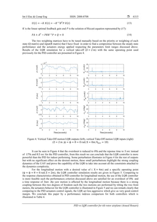
In a second test, we try to perform a longitudinal motion of ( X = 4m) at an equilibrium point
(ψ = ϕ = θ = 0 rad; Z = 2m; Vhov = 10) like illustrate in Figure 3. From Figure 3, our UAV will have
the same problem for indoor reference tracking for longitudinal motion because there is an overshoot of
10% ; we notice also that our UAV in the longitudinal motion is quick comparing to the vertical take-off
motion with a response time about 6 sec. The two motion performed above indicate that the PID controllers
are not a good controller for indoor reference tracking according to the simulation in Figures 2 and 3 because
of the strong coupling of the UAV system dynamics, in order to solve this problem, we have to choose
another controller that takes into account all the coupling effects of the UAV dynamics, the most well-known
regulator for linear systems which can perform well for indoor motion, minimizing the cost function and give
us more feasible solution of this problem is a the LQR controller. Using a single LQR controller will help us
to feedback all the states in one step (based on matrix calculus) to select the desired output however in
PID controller we have used a multiple PID’s because that the PID can cover just one channel (based on
scalar calculus) so five PID’s are used for comparing all the outputs with the outputs generated from
LQR controller.
Figure 3. Longitudinal motion PID outputs (left), longitudinal motion PID inputs (right)
(Z = 2 m ;ψ = ϕ = θ = 0 rad; X = 4m; Vhov = 10)
The LQR controller is used to obtain the best control sequence that minimizes the cost function
detailed in the equation below [14, 24, and 25], using the state space representation in (12):
𝐽 = ∫ 𝑋(𝑡) 𝑇
𝑄 𝑋(𝑡) + 𝑈(𝑡) 𝑇
𝑅 𝑈(𝑡)
∞
0
(12)
where R is a positive definite weighting matrix and Q is a weighting matrix that can be positive semi-definite,
U(t) represents the optimal control law detailed in the equation above:](https://image.slidesharecdn.com/22218331jun20may30dec19y-201223022759/85/PID-vs-LQR-controller-for-tilt-rotor-airplane-6-320.jpg)
![ ISSN: 2088-8708
Int J Elec & Comp Eng, Vol. 10, No. 6, December 2020 : 6309 - 6318
6316
Figure 5. Longitudinal motion LQR outputs (feft), longitudinal motion LQR inputs (right)
(Z = 2 m ;ψ = ϕ = θ = 0 rad; X = 4m; Vhov = 10)
Table 4. PID and LQR performance indexes comparison
PID Types PID VTOL LQR VTOL PID Longitudinal LQR Longitudinal
Overshoot (%) 17 0 10 0
Response Time (sec) 8.5 3 6 3
Control precision (%) 0.016 0.001 0.012 0.001
5. CONCLUSION
In this paper we have developed a dynamic mathematical model for a tilt rotor airplane, aiming to
perform a vertical take-off and longitudinal motions, two control technics are proposed and applied on
a linear dynamics model. The simulation results of both of the controllers were compared using some
performance indexes such as the overshoot, response time and control precision, the LQR controller was
more powerful comparing to PID controller in all performance indexes for both vertical take-off and
longitudinal motions.
REFERENCES
[1] C. Papachristos, K. Alexis, A. Tzes., “Linear Quadratic Optimal Trajectory-Tracking Control of a Longitudinal
Thrust Vectoring-Enabled Unmanned Tri-Tilt Rotor,” Thirty-Nine Annual IEEE Conference Industrial Electronics
Society, pp. 4174-4179, 2013.
[2] D. Anh Ta, I. Fantoni, R. Lozano., “Modeling and Control of a Tilt tri-rotor Airplane,” American Control
Conference, pp. 131-136, 2012.
[3] C. Papachristos, K. Alexis, A. Tzes., “Trajectory Control of an Unmanned Tri-Tilt Rotor in Hover Flight via Direct
Longitudinal Actuation,” Twenty-First Mediterranean Conference in Control and Automation, pp. 369-374, 2013.
[4] K.T. Oner, E. Cetinsoy, E. Sirimoglu, C. Hancer, T. Ayken, and M. Unel., “LQR and SMC Stabilization of a New
Unmanned Aerial Vehicle,” World Academy of Science, Engineering and Technology, pp. 554-559, 2009.
[5] J. Escarefio, A. Sanchez, O. Garcia and R. Lozano., “Triple Tilting Rotor mini-UAV: Modeling and Embedded
Control of the Attitude,” American Control Conference, pp. 3476-3481, 2008.
[6] L. Feng, Z. William, D.B. Robert., “Robust Hovering Control of a PVTOL Aircraft,” IEEE Transaction on Control
Systems Technology, vol. 7, no. 3, pp. 343-351,1999.
[7] M. Kara, A.Lanzon., “Design and Control of Novel Tri-rotor UAV,” Proceedings of 2012 UKACC International
Conference on Control, pp. 304-309, 2012.](https://image.slidesharecdn.com/22218331jun20may30dec19y-201223022759/85/PID-vs-LQR-controller-for-tilt-rotor-airplane-8-320.jpg)
![Int J Elec & Comp Eng ISSN: 2088-8708
PID vs LQR controller for tilt rotor airplane (Aoued Houari)
6317
[8] P. Fan, X. Wang, K.Y. Kai., “Design and Control of a Tri-rotor Aircraft,” International conference on Control and
Automation, pp. 1972-1979, 2010.
[9] H. Gu, X. Lyu, Z. Li, S. Shen and F. Zhang., “Development and Experimental Verification of a Hybrid vertical
Take-off and Landing(VTOL) Unmanned Aerial vehicle(UAV),” International Conference on Unmanned Aircraft
Systems, pp. 160-169, 2017.
[10] G. Francisco, V. Rafael, F. C. Eduardo., “An iterative Model Predictive control Algorithm for UAV Guidance,”
IEEE Transactions on Aerospace and Electronic Systems, vol. 51, no. 3, pp. 2406-2419, 2015.
[11] S. Yoon, S. J. Lee, B. Lee, C. J. Kim, Y. J. Lee and S. Sung, “Design and Flight Test of a Small TriRotor
Unmanned Vehicle with a LQR Based Onboard Attitude Control System,” International Journal of Innovative
Computing, Information and Control, pp. 2347-2360, 2013.
[12] D. W. Yoo, H. D. Oh, D. Y. Won and M. J. Tahk, “Dynamic Modeling and Stabilization Techniques for Tri-Rotor
Unmanned Aerial Vehicles,” International Journal of Aeronautical and Space Science, vol. 11, no. 3, pp. 167-174, 2010.
[13] D. T. Huang, T. H. H. Le and N. H. Nguyen, “Adapting SE (3) Nonlinear Geometric Method to Control Single-Tri
Rotor with Integrator,” American Journal of Aerospace Engineering, pp. 96-105, 2018.
[14] Y. Q. Zhang, W. P. Zhaw and S. Xiang, “Control Law and Simulation Analysis of Vertical Take-Off and Landing
Stage of Tilt-Rotor Aircraft,” Journal of Advanced Materials Research, pp. 521-524, 2015.
[15] S. K. Pandey, J. Dey and S. Banerjee, “Design of Optimal PID Controller for Control of Twin Rotor MIMO System
(TRMS),” Advances in Power and Control Engineering, pp. 93-106, 2020.
[16] M.A. Ahmad, S.I. Azuma and T. Sugie, “Performance analysis of model-free PID tuning of MIMO systems based
on simultaneous perturbation stochastic approximation,” Expert Systems with Applications, pp. 6361-6370, 2014.
[17] M.R.B. Ghazali, M.A.B. Ahmad and R. Ismail, “Adaptive safe experimentation dynamics for data-driven
neuroendocrine-PID control of MIMO systems,” IETE Journal of Research, pp. 1-14, 2019.
[18] C. Chen, J. Zhang, D. Zhang and L. Shen, “Control and Flight Test of a Tiltrotor Unmanned Aerial Vehicle,”
International Journal of Advanced Robotic Systems, pp.1-12, 2017.
[19] C. S. Yoo, S. D. Ryu, B. J Park, Y. S Kang, C. M Elias and S. B Jung, “Actuator controller based on Fuzzy Sliding
Mode Control of Tilt Rotor Unmanned Aerial Vehicles,” International Journal of Control, Automation and
systems, vol. 12, no. 6, pp. 1257-1265, 2014.
[20] M. Nasr, M. Ashraf, M. S Hussein, A. S Salem, C. M Elias, O. M Shehata and E. I Moragn., “A comparative study
on the control of UAVs for Trajectory tracking by MPC, SMC, Backstepping, and Fuzzy Logic controllers,”
IEEE International Conference in Vehicular Electronics and Safety, pp. 1-6, 2018.
[21] Z. Prime, J. Sherwood, M. Smith, and A Stabile, “Remote Control Vertical Take-off and Landing Model Aircraft,”
Level 4 Honors Project Final Report, 2005.
[22] Ch. B. Prakash, R. S Naik, ”Tuning of PID Controller by Ziegler Nichols Algorithm for Position Control of DC
Motor,” International journal of Innovative Science,Engineering and Technology, vol. 1, no. 3, pp. 379-382, 2014.
[23] T. R. Kurfess, "Getting in tune with Ziegler-Nichols," Academic Viewpoint column, Control Engineering magazine,
2007.
[24] K. K. Yit, P. Rajendran, and L. K Wee, “Proportional-derivative Linear Quadratic Regulator Controller Design for
improved Longitudinal Motion Control of Unmanned Aerial Vehicles,” International journal of Micro Air
Vehicles, vol. 8, no. 1, pp. 41-50, 2016.
[25] A. M. Ayad, H. Wahid, ”Optimal Tuning of Linear Quadratic Regulator controller Using a Particle Swarm
Optimization for Two-Rotor Aero dynamical System,” International journal of Electronics and Communication
Engineering, pp. 196-202, 2017.
BIOGRAPHIES OF AUTHORS
Aoued Houari Was born on 1985 in Relizane, Algeria. He received his B.S (State engineer)
Engineering degree in automatism from University of Sciences and Technology of Oran (USTO-
MB), Algeria, in 2008. He received his M.S (Magister) degree in Electronics, Automatic,
Robotic and productic option from USTO-MB University in 2012. He is currently an associate
professor at UHBC university. His main research interest is within the control and applications
of advanced control technics, design and control of UAV.
Imine Bachir was born on 1962 in Oran, Algeria. He received his B.S (State engineer)
Engineering degree in mechanical engineering from University of Sciences and Technology of
Oran (USTOMB), Algeria, in 1986. He received his M.S (Magister) degree in Mechanical
engineering, option: Energetical from USTO-MB university in 1993. He received his PHd in
Mechanical engineering, option: Energetical from USTO-MB university in 2004. He is currently
an associate professor in USTO-MB University since 1987. His main research interest is UAV
aerodynamic design.](https://image.slidesharecdn.com/22218331jun20may30dec19y-201223022759/85/PID-vs-LQR-controller-for-tilt-rotor-airplane-9-320.jpg)