1. > REPLACE THIS LINE WITH YOUR PAPER IDENTIFICATION NUMBER (DOUBLE-CLICK HERE TO EDIT) < 1
Abstract— Each year, over a million fatalities by automobile
accidents are recorded. Some of the most destructive accidents
are the multiple-vehicle collisions caused when drivers do not
have enough time to stop safely, thus, end up colliding with the
existing debris of a previous accident. The challenge presented is
developing a way to alert drivers of the existing debris from a
furtherdistance away, so they will have a longerperiod of time to
avoid the collision. The Accident Alert Drone is a quadcopter
that approaches the core of the problem directly by using a light
to alert drivers of the upcoming hazard from a distance further
away. The low-fidelity prototype of the quadcopter is capable of
remotely controlled flight and autonomous altitude and
positional mapping. The application of the Accident Alert Drone
aims to significantly reduce the number of fatalities that occur
each year due to multiple-vehicle collisions.
I. INTRODUCTION
S a result of traffic accidents, an American dies every 11
minutes.1 The catastrophe is worsened when more cars
are involved in the accident, leading to a multiple-vehicle
collision. This situation is common when an accident happens
in a low-visibility region where the incoming drivers do not
have enough time to react properly. For instance, curved roads
or bad weather conditions are main factors that might
contribute to this type of accident. Even if drivers follow the
traffic laws, they are still in danger of being involved in an
accident. The traffic regulations are safe and smooth to follow
if everything is going well on the roads. However, if an
accident is already there, it is a different story. Indeed, the
Accident Alert Drone is needed for an important alerting and
rescuing mission. The quadcopter will dispatch from a
position near the accident and fly towards the oncoming cars,
lighting a flare, therefore giving them adequate time to react.
Before addressing its specifications, a brief appreciation for
quadcopters’ origins will follow.
In 1907, Louis and Jacques Breguet in association with
Professor Charles Richet flew the first quadcopter named
Gyroplane No. 1 to a maximum height of 1.5m. That was four
years after the Wright Brothers invented the first airplane.
Gyroplane No. 1 was the first machine to raise vertically off of
the ground using four rotors. Surprisingly, it was a manned
machine that required a pilot to ride inside. Furthermore,
Gyroplane No. 1 was uncontrollable in a horizontal plane, so a
man had to hold the end of each arm to stabilize it. In 1908,
the Breguet aircraft was developed to fly to a height of 4.5m,
but unfortunately, it wrecked completely upon landing. In
conclusion, stability is a significant issue for quadcopters.
In his webpage from 2013, Yuan Gao addresses that having
four rotors can be disadvantageous because they reduce the
stability of the aircraft. Although it is cost efficient and easier
to have four smaller motors instead of having one complex
motor at the center like a helicopter, a system of electronic
stabilization is required because it is impossible for a pilot to
keep the quadcopter in balance. In order to overcome that
problem, Gao points out that the problem will be insignificant
on the scale of small quadcopters. As a result, the applications
of quadcopters have been mostly driven to a scale of a few
feet long in diameter. For example, quadcopters serve as a
research platform used by universities for testing and
evaluating new ideas in different fields, such as flight control
theory, navigation, and robotics. Also, quadcopters are used
commercially to serve agricultural purposes, such as
measuring the height of crops. The purpose of the Accident
Alert Drone is, as mentioned, to prevent multiple-vehicle
collisions caused by low-visibility conditions on the roads.
The first stage of prototyping involved drawing rough
sketches of each component on a whiteboard. The designs
focused on several themes, such as creativity, cleanliness,
simplicity, durability, and weight minimization. The second
stage of designing utilized SolidWorks software to draft the
sketches in order to provide a well-dimensioned visual
representation of the prototype. Next, 3-D printers and non-
automated machines were used to manufacture the designs on
the selected materials. After assembling these parts, the body
of the quadcopterwas ready to have the electronic components
mounted and wired properly on it. Finally, the codes were
uploaded to the Arduino to have a remotely controlled
quadcopterfeaturing an autonomous altitude mapping system.
II. CAD MODELS
The Base 11 fellows used SolidWorks software to CAD
well-dimensioned parts that fit within the program's
curriculum requirements. Multiple parts were designed by
different team members, then assembled together using the
same software. Some files of small parts were converted to
.STL files to be readable by 3-D printers. For bigger pieces,
the drawings were exported from SolidWorks into CorelDraw
to be readable by automated laser cutters.
The Accident Alert Drone
Will O’Connell1
, Huda Sedaki1
Henry Ford College
A
2. > REPLACE THIS LINE WITH YOUR PAPER IDENTIFICATION NUMBER (DOUBLE-CLICK HERE TO EDIT) < 2
A. Top Layer of the Base
The purpose of the top layer is to provide enough surface
area for mounting every electronic component on the same
layer. The shape of the base is an octagon with rectangular
arms symmetrically attached to four of its sides. In the design
of many quadcopters, the arms are independently attached to
the base using unnecessary fasteners. To reduce the amount of
fasteners, the top layer of the Accident Alert Drone’s base has
all four arms and the central octagon combined as one piece.
The top layer is made out of polycarbonate because the
material is thin, glossy, pliable and able to resist torsion.
B. Middle Layer of the Base
The middle layer supports the first and third layers by
adding rigidity that prevents the arms from twisting or
snapping. Initially, acrylic was considered as an appropriate
material because of its hardness. However, acrylic is heavy
and prone to cracking. To overcome this problem, foam was
used because it is lightweight, yet it retains its stiffness.
C. Bottom Layer of the Base
The bottomlayer has the same shape as the other two layers
where the arms and base form one piece. The bottom layer is
made of Italian Poplar wood because it is sturdy, lightweight,
and is the same thickness as the material of the propeller
guards. The width of the wooden arms were made to be less
than the other two top layers so that the propeller guards can
slide onto the wood to interlock. As a result, the bottomplane
integrates the propeller guards with the base to form one
surface.
D. Propeller Guards
The propeller guards protect people in the path of the
quadcopter from being injured by the spinning propeller
blades. The radius of the propeller was measured and a
semicircle with a radius larger than the propeller was created
to provide a safer room around the propeller. Consequently, if
the quadcopter collided with a person, the guard that is
extruding would block the propeller from coming into contact
with them. A material called coroplast, which is an
abbreviation for corrugated plastic, was used. Coroplast is an
anisotropic material that is flexible when stress is applied
perpendicularly to the grains, but rigid if it is applied along
them. The grains were aligned so that the direction of rigidity
would match the direction of impact. A section of the
propeller guard was cut out so that it interlocks with the
wooden arms so that they could lie on the same plane without
sticking out.
E. Landing Gear
The landing gear provides a soft landing by absorbing the
impact produced upon landing. The old model of the landing
gear consisted of a U-shaped piece designed in SolidWorks.
That piece was cut out of polycarbonate. Then, it was placed
over a heat strip where the high temperature allowed it to be
bent into the U-shape. It was attached through the motor
mount with the bottom of the quadcopter's arm. Then, a
rectangular piece of foam with a rounded bottom was inserted
into the U-holder. To fasten the two pieces together, a
horizontal bolt and nut would go through the U-holder across
the foam. The rounded bottom of the foam piece enables the
quadcopter to roll and return to its balanced position when the
quadcopter lands at an angle. The landing gear was made out
3. > REPLACE THIS LINE WITH YOUR PAPER IDENTIFICATION NUMBER (DOUBLE-CLICK HERE TO EDIT) < 3
of foam, because the foamis lightweight, rigid and absorbs the
impact. The landing gear is relatively long to protect the
components from direct contact with the ground. After our
first flying test, the foam piece rotated around the horizontal
bolts due to an angled landing. To prevent that, some electrical
tape was placed horizontally around the U-holder to prevent
the foam from rotating.
Later, a new open-base cuboid replaced the U-holder by
eliminating the use of tape. It was attached the same way as
the old U-holder after being manufactured using a 3-D printer.
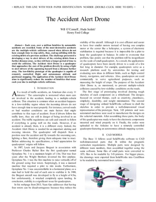
F. Ultrasonic SensorHolders
It is preferable to place the electronics as cleanly and
tightly as possible, so a 3-D printed holder with exactly fitting
dimensions satisfies these requirements. The sensor would
slide into it as calculators slide into their cases. Two of the
holders were L-shaped (Left figure) so that each sensor can
face a wall to measure a distance for the X and Ycoordinates.
The blue part of the L-shaped holder is to screw it into the
base. The red part is to have the sensor inserted between the
two yellow notches that were cut into its sides. The third
sensor holder was U-shaped (Right figure) so that it can face
the ground to get the Z coordinate.
The material used for 3-D printing is rigid, which would
stabilize the sensors on the quadcopter if the flight was
unstable. Well-stationed sensors will take more precise
measurements. In order to design a small and fine-detailed
piece, taking precise measurements of the dimensions was
essential for the parts to match. Also, setting a tolerance range
was necessary since the machines and the materials were not
perfect. When checking the results, the first holder needed to
be sanded because it was too tight for the sensor to fit. By
taking that feedback, the tolerance was applied to the CAD
models of the other two sensors, which produced perfect
results.
III. ELECTRONIC COMPONENTS FOR FLIGHT CONTROL
Piloting a quadcopter is simply controlling the speed of its
four motors. Since it is impossible to manually apply the
correct speed for each motor while ensuring the altitude,
direction, and the movement speed of the entire quadcopter,an
electronic system is required to control the flight. It is easier
for a human to control four things instead: pitch, roll, yaw, and
altitude. The pitching moment enables the quadcopter to rotate
about a horizontal axis; for instance, a downward pitch occurs
if the back of the quadcopter raises to cause a forward
acceleration. The rolling moment is similar to the pitching
moment since it also enables the quadcopter to rotate about a
horizontal axis. However, rolling involves the right and left
sides of the quadcopter; for instance, rolling occurs if the left
side of the quadcopter is raised, causing the quadcopter to
undergo an acceleration to the right. Additionally, the yawing
moment enables the quadcopter to revolve horizontally
clockwise or counterclockwise around a vertical axis that
passes through its center. Finally, adjusting the amount of
throttle controls the altitude of the quadcopter. The user can
access these four control options with a remotely controlling
transmitter. The transmitter sends the signal through the
receiver, NAZA (flight control system), speed controllers, and
finally to the motors.
A. Transmitter
The transmitter is the remote control of the quadcopter. For
this project, a six-channel transmitter was used to control the
flight of the quadcopter. The transmitter has two sticks used
for piloting. One of the sticks controls the throttle when it is
moved vertically and controls the yaw/heading when it is
moved horizontally. The other stick controls the pitch when
moved vertically and controls the roll when moved
horizontally. The transmitter sends this data through four
channels to the receiver in the form of radio signals produced
by an antenna.
B. Receiver
The receiver is the port that accepts the signals of the
transmitter by an antenna. Then, these signals are transmitted
to the flight control system (NAZA).
C. Flight Control System (NAZA)
The NAZA represents the brain of the quadcopter which is
responsible for its stability and maneuverability features. It
receives the PWM signals fromthe receiver and outputs speed
values that will go to the motors. Depending on the user's
desired pitch, yaw, and roll, the NAZA calculates the speed of
each of the four motors to produce a motion that follows the
user’s commands. For instance, all of the four speeds are kept
equal if the user has the pitching stick of the transmitter
centered; once that stick is shifted, the NAZA will follow that
command.
D. Electronic Speed Controller (ESC)
The ESC operates the motor with the speed value that was
received from the NAZA. It also supplies the motor with an
alternating current that was converted from the direct current
4. > REPLACE THIS LINE WITH YOUR PAPER IDENTIFICATION NUMBER (DOUBLE-CLICK HERE TO EDIT) < 4
of the power supply.During the setup process, the ESC should
be calibrated using a transmitter to insure that all the motors
are synced to the same channel (throttle channel).
E. Brushless Motors
A brushless motor consists of permanent magnets on its
rotor that can rotate around stationary electromagnets inside
the motor. Changing the polarity of the electromagnets
consecutively to attract or repel the permanent magnet creates
the rotational motion. Each of the four motors needs to be
distributed evenly on the four arms so that they are
symmetrical with respect to the center of the quadcopter. The
motors rotate with their attached propellers to provide the
necessary lift force.
F. Power Supply
An 11.1V / 3 Cell rechargeable battery provides the
quadcopter with the power needed to fly and perform the
altitude-mapping task. The working period of the battery on
this prototype is approximately thirty minutes. It weighs 239g
which increases the weight of the quadcopter significantly. In
order to increase the duration of the flight, a higher voltage
battery should be used. However, increasing the number of
cells will increase the battery’s weight, which as a result will
require more lifting power. Greater lifting power will drain the
battery at a faster rate. As a result, increasing the number of
cells would not be very efficient.
IV. ELECTRONIC COMPONENTSFOR AUTONOMOUSALTITUDE
MAPPING
The Accident Alert Drone’s autonomous feature is altitude
and positional mapping. The quadcopter is able to display its
orientation, height, and location when it is in an enclosure.
This feature utilizes multiple sensors on the quadcopter that
take measurements. These measurements are inputted into an
Arduino to check if certain conditions are met before this
Arduino wirelessly sends instructions to another Arduino that
is attached to a LED panel.
A. Inertial Measurement Unit (IMU Sensor)
The IMU is a chip that houses an accelerometer, gyroscope,
and magnetometer. The IMU is responsible for three
measurements: angular velocity, acceleration, and heading.
The gyroscope determines the speed and direction of rotation
(angular velocity) of the quadcopter. The accelerometer
measures the change of the shifting speed of the quadcopter
with respect to the X, Y, & Z axes. The magnetometer
determines the direction of the quadcopter's heading by
detecting tiny changes in the Earth's magnetic fields.
B. Arduino Uno
The Arduino Uno is an open-source prototyping platform
based on easy-to-use hardware and software. It has 14 digital
pins and 6 analog pins; each of these pins can be designated as
an input or an output port. In order to do that, a code must be
uploaded to the Arduino from a computer. Since the Arduino
software is open-source, there are many written programs in
the Arduino IDE* free library. (IDE stands for Integrated
Development Environment, which represents the Arduino
programming language that is similar to C and C++).
For this project, two Arduino Uno boards were needed. The
first one, mounted on the quadcopter, does the necessary
computations for altitude mapping. The IMU and the
ultrasonic sensors input information fromthe environment into
the Arduino through wires connected to the Arduino pins.
Then, the code that was uploaded to the Arduino applies
logical statements to get the desired output. The second
Arduino on the ground station controls the lighting of the LED
panel.
C. Ultrasonic Sensors (HC-SR04)
An ultrasonic sensor calculates the distance between the
sensor and another object. The ultrasonic sensor works by
emitting a sound wave in one direction. That sound wave
travels until it bounces off an object and returns to the sensor.
The ultrasonic sensor detects the time it takes to receive the
echo and uses that measurement to calculate the distance. On
the quadcopter, ultrasonic sensors are used to detect the
elevation from the ground and the position of the quadcopter
in an enclosed space.
D. XBee WiFi Modules
The purpose of using a couple of XBee WiFi Modules is to
create a peer-to-peer network that enables two devices to
wirelessly transmit information with each other. A private
network between both XBees was formed by syncing them
together using a program called XCTU. Each XBee WiFi
module was attached to a different Arduino. The first Arduino
is on the quadcopter and the second Arduino is attached to an
LED ground station. The first XBee relays the quadcopter
Arduino's output as a wireless signal to the XBee on the
ground station.
E. XBee Explorer
The XBee Explorer is a circuit board that serves as an XBee
to Mini USB adapter. The XBee Explorer provides a
connection between the XBee and a computer so that the
XCTU program is utilized to set up a private wireless network
between both of the XBees.
F. XBee Shield
The XBee Shield is a circuit board with the same form
factor as an Arduino Uno that makes the XBee compatible
with an Arduino.
V. PROGRAMMING THE ARDUINO
The altitude-mapping task required three main blocks of
code. Two of these blocks were uploaded to the Arduino
mounted on the quadcopter, which are the main and the send
codes. The main code contains conditional statements that
check the stability of the flight. If the quadcopter is leveled,
the sensors' readings will be processed. Additionally, the main
code includes logical statements that check the distance
readings and compare them to a set of boundary conditions to
determine the location of the quadcopter inside the enclosure.
Then, it outputs a corresponding quadrant number to indicate
5. > REPLACE THIS LINE WITH YOUR PAPER IDENTIFICATION NUMBER (DOUBLE-CLICK HERE TO EDIT) < 5
the position and a color to indicate the height.
After that, the send code breaks these two outputs into bytes
and sends them wirelessly via an XBee that is synced to
another XBee on the ground station.
After receiving this wireless signal of bytes, the receive
code on the ground station’s Arduino assembles and translates
the information to light up the corresponding color and
quadrant on the LED panel.
VI. CONCLUSION
In summary, the Accident Alert Drone provides the drivers
with more time to avoid crashing into existing debris of a
previous accident by signaling emergency warnings. The first
prototype of the Accident Alert Drone is capable of two
important tasks. First, it can be remotely controlled to fly
within a user's line-of-sight for about 30 minutes. Secondly, it
can perform altitude mapping tasks in a bounded area
autonomously.
Beyond the scope of the eight-week project, future plans
involve implementing three features. First, the drone needs to
be completely autonomous to fly safely beside the roads. The
reaction time of a human is insufficient for micromanaging
piloting next to vehicles or in extreme weather conditions.
Complete autonomy requires that the quadcopter is equipped
with a GPS to aid in positioning.
The second feature for the Accident Alert Drone is
geometric mapping/analysis to scan for accidents without user
input. In an incident-free zone, the outline of a car below will
be rectangular. When a collision occurs, the rectangular
shapes of the two bodies will conjoin and deform. The
quadcopter’s programming will detect the difference in
geometry and conclude that an accident has occurred.
The final feature will be a display screen attached to the
quadcopter. The screen will show the distance between a
driver’s current position and the accident as the quadcopter
flies towards them.
ACKNOWLEDGMENT
We would like to thank Base 11, The Henry Samueli School
of Engineering, University of California, Irvine, & The Office
of Access & Inclusion. We would also like to extend our
gratitude to the following individuals: Dr. Sharnnia Artis, Ms.
Verenice Mojica, Mr. Edward Lau, Ms. Gillian John, Dr.
James Smith, Dr. Janice Gilliland, & Dr. Hassan Nameghi.
REFERENCES
[1] "FAST & EASY." ItsMyLife: How Many People Die in America. N.p., n.d. Web. 05 July
2016.
Will O'Connell was born in Orange,
California, in 1994. He is currently
enrolled in his sophomore year at Henry
Ford College in Dearborn, Michigan
where he is seeking an Associat Degree
in pre-engineering. He plans to transfer
to a four-year university where he will
pursue a Masters in Environmental Engineering.
Huda Sedaki was born in Damascus,
Syria, in 1996. She completed her pre-
college education in Syria. She got her A.D
in Science, Pre-Engineering from Henry
Ford College in Dearborn, Michigan, in
2016. She has tutored college-level math
and physics at Henry Ford College. She is
currently enrolled in her Junior year at Wayne State University
in Detroit, Michigan where she is seeking a B.S in Mechanical
Engineering.