Download as PDF, PPTX


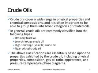


![physical property prediction
Riazi and Daubert (1987) developed a simple twoparameter equation for predicting the physical
properties of pure compounds and undefined
hydrocarbon mixtures.
θ = a (M)b γc EXP [d (M) + e γ + f (M) γ]
based on the use of the M and γ of the undefined petroleum
fraction as the correlating parameters.
Where
θ = any physical property
•
•
•
•
Tc = critical temperature, °R
Pc = critical pressure, psia
Tb = boiling point temperature, °R
Vc = critical volume, ft3/lb
a–f = constants for each property
γ = specific gravity of the fraction
M = molecular weight
Fall 13 H. AlamiNia
Reservoir Fluid Properties Course:
43](https://image.slidesharecdn.com/q921-rfp-20lec3-131102221256-phpapp01/85/Q921-rfp-lec3-43-320.jpg)


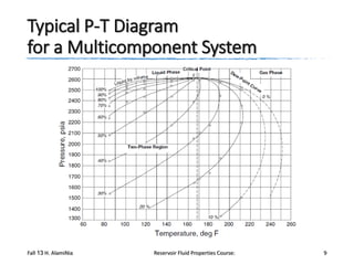
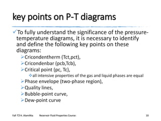
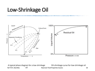
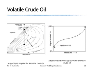
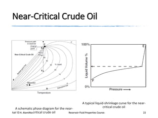
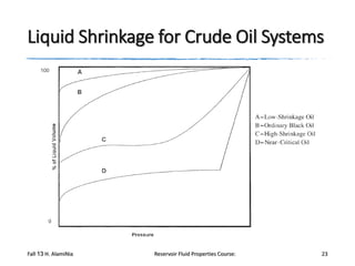
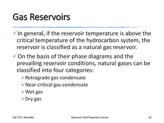
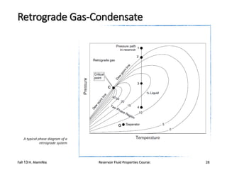
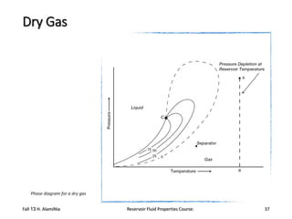
The document provides an overview of a course on reservoir fluid properties. It discusses different types of hydrocarbon reservoirs and how they are classified. It describes the phase behavior of hydrocarbon mixtures using pressure-temperature diagrams. Key points on these diagrams are defined, including the bubble point curve, dew point curve, and critical point. Based on the position of the initial reservoir pressure and temperature on the diagram, reservoirs can be classified as oil or gas reservoirs. Oil reservoirs are further divided into undersaturated, saturated, and gas-cap categories. Common types of crude oils like ordinary black oil, low-shrinkage oil, and volatile oil are also described. Gas reservoirs include retrograde gas-condensate, near-critical gas-condens