1. WATER TREATMENT
•Water treatment varies depending on the
produced oil quality
• Heavy oils and tight emulsions need more
treatment than light condensate found on
gas platforms
• Use Hydrocyclones if pressure > 8 barg
• Heavy emulsion forming oils need other
treatment e.g. induced or dissolved air
flotation (DAF) and Walnut shell filtration
2.
2. WATER TREATMENT(cont.)
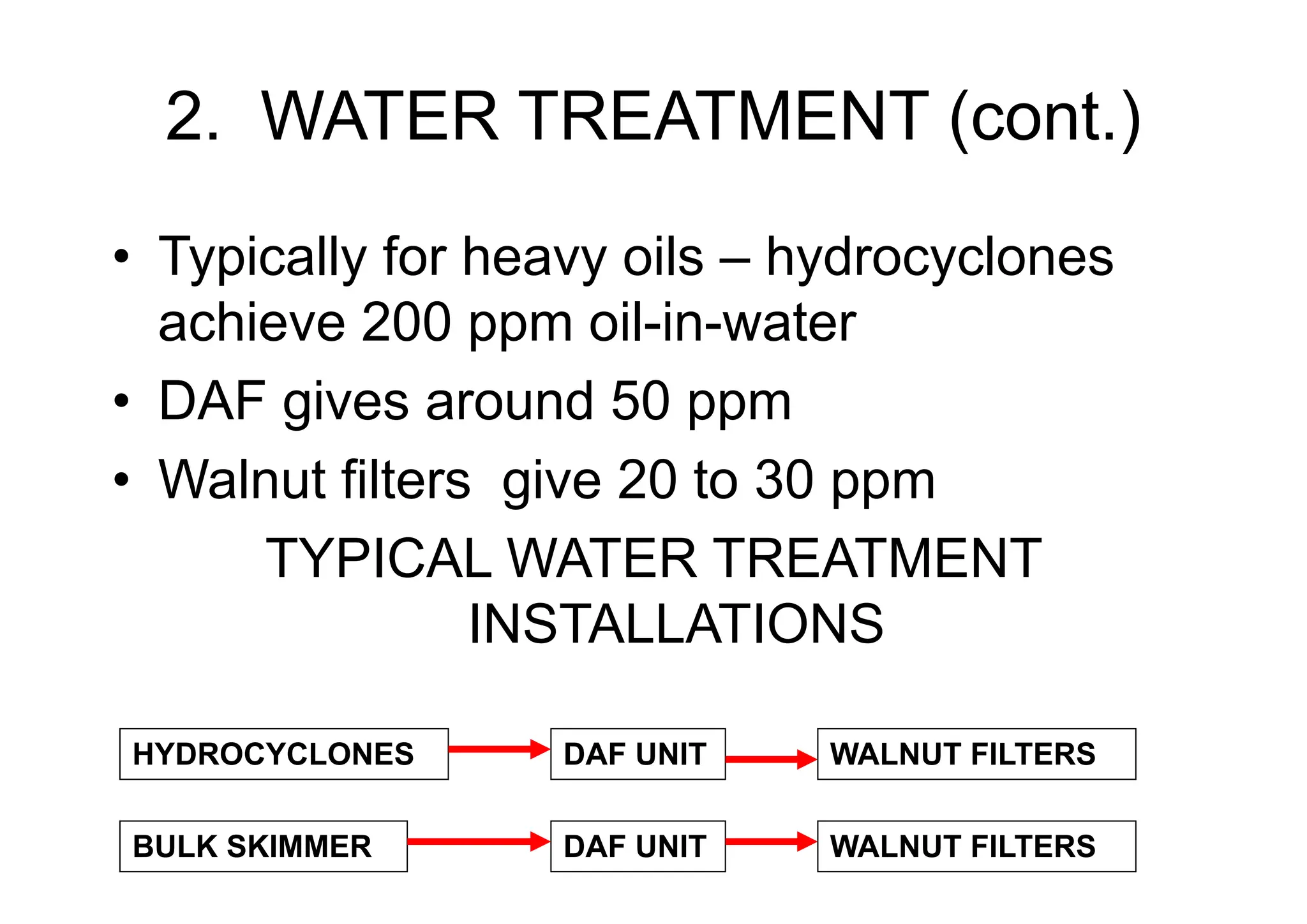
• Typically for heavy oils – hydrocyclones
achieve 200 ppm oil-in-water
• DAF gives around 50 ppm
• Walnut filters give 20 to 30 ppm
TYPICAL WATER TREATMENT
INSTALLATIONS
HYDROCYCLONES DAF UNIT WALNUT FILTERS
BULK SKIMMER DAF UNIT WALNUT FILTERS
3.
3. EQUIPMENT DESIGN
•Heat Exchangers – Data from simulations incl.
Heating/cooling curves
• Specify all operating cases, not just maximum
duty
• Common practice is to add a safety margin – do
this with caution – detrimental in high fouling
cases
• Cooling water exchanger – keep temperatures
below 49ºC and velocities above 1.2 m/s
• Use maximum 10ºC approach temperature
4.
4. EQUIPMENT –HEXs (cont.)
• Try to make design pressure on low
pressure side = min. 2/3 (or 4/5) DP on HP
side to avoid tube rupture relief case
• For Hot Oil Circuits, if possible, DP of Hot
Oil side > DP of process side
• For S/T HEX with high fouling service on
shell side – prefer to use square tube pitch
5.
5. EQUIPMENT -VESSELS
• Sizing – use Shell DEPs
• Two phase sep with mostly gas, use
vertical sep for space saving
• Where there is a lot of liquid, use
horizontal seps
• Internals - momentum breaker, demisting
pack, foam breaking baffles, vortex
breakers, water weirs, baffles to stop pitch
and roll effects on FPSOs, sand jets, plate
packs for water removal
6.
6. EQUIPMENT -PUMPS
• PD pumps for high head low flow
• For low or high heads, high flow rates use
centrifugal
• centrifugal preferred if possible
• For High viscosity, low shear pumps use low
speed Screw Pumps – consider variable speed
for level control
• Design downstream piping for shutoff head –
always specify head in preference to pressure
• Power kW = m3/s x kPa. Efficiency from 50 to
80% depending on pump size
7.
7. PUMP SYSTEMDESIGN
• All pumps must have the NPSHA specified
so we have to calculate it.
• In our processes, we often pump saturated
liquids.
Pf
H
H = static head above pump suction
NPSHA = (P1 + atm - Pf - Pv)/ρg + H – Ha – Hv
P1
P1 = Vessel pressure
Pf = Friction pressure loss
Pv = vapour pressure
For a centrifugal pump, pumping a saturated liquid,
Pv = P1 + atm and so NPSH = H - Pf/ρg
NPSHA must be necessarily greater than
NPSHR
Ha = acceleration head (only for PD pumps)
Hv = velocity head (normally ignored)
8.
8. PUMP SYSTEMDESIGN (cont)
• It is not good practice to use a PD plunger
pump for saturated liquids because of the
acceleration effects.
• Acceleration of the liquid can produce
velocities 3 times the average (pressure
drops 9 times average) – causing
vaporization.
9.
9. EQUIPMENT -
COMPRESSORS
•Centrifugal compressors for low maintenance
• Multistage with intercooling
• Antisurge control for each stage
• Surge is caused by flow reversal at low flows
• Surge control is by flow control from
downstream of discharge scrubber back to
suction
• Hot quick opening bypass may be required if
dynamic simulation shows it is needed
• Stonewall – when sonic velocity in compr.
10.
10. COMPRESSORS (cont.)
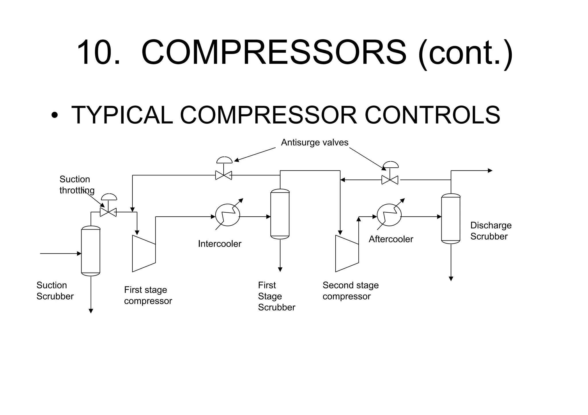
•TYPICAL COMPRESSOR CONTROLS
Suction
Scrubber
First stage
compressor
Intercooler
Aftercooler
Second stage
compressor
First
Stage
Scrubber
Discharge
Scrubber
Antisurge valves
Suction
throttling
11. GENERAL DESIGN
•Line Sizing
• Velocity (erosional velocity for 2-ph lines)
• Pressure drop
• Flow regime (2-ph flow) – avoid slug flow
• Don’t add too much design margin
• Add design margin for high fouling services
e.g. drains
• Remember small sizes weigh less, cost
less, take up less space – all important for
offshore work
13.
12. LINE SIZINGRULES OF
THUMB
• Pump Suctions: no more than 20 kPa per
100m. Boiling liquids NPSHA>NPSHR.
• Compressor Suctions and discharges:
COOEC standard
• Flare headers: design according to PSV
back pressures.
• For high pressure high flow PSVs, also
calculate noise as special design may be
needed
14.
13. LINE SIZINGRULES (cont.)
• Pump Spillbacks, no criteria for pressure
drop - keep below erosional velocity (API-
14E continuous flow).
• All other lines: no more than 50 kPa per
100 m.
• Avoid noise by restricting velocities such:
Gas- v < 100/√ρ where ρ kg/m3 and v m/s
Liquid - v < 9 m/s
15.
14. LINE SIZING– PRESSURE
DROP CALCULATIONS
• Liquids - Darcy formulae, or API 14E, or “Crane”
equations
• Compressible fluids with high pressure drops
use Isothermal Flow equation
• Can also use Panhandle and Weymouth
formulae but these are theoretically not as
accurate.
• Commercial software like Pipesim
• Friction factor - Colebroke White or Chen
equation
• Ensure you have the pipe spec
16.
15. CONTROL VALVESIZING
• Determine the range of flow rates
• Hydraulic calcs u/s and d/s to calculate
valve u/s and d/s pressures at various flow
rates
• Get operating data from simulations or
data base - viscosity, cp/cv, MW (gases),
S.G., critical properties and vapour
pressures (for liquids).
17.
16. CONTROL VALVESIZING
• Size the control valve to allow piping
layouts to be progressed
• If Fisher valves used – ‘e’ body globes are
most common
• Calculate Cv using the Fisher Firstvue
program or manually from cat. 10 for the
various flow rates
• For the range of flow rate, select a control
valve that is between 25 and 70% open
18.
17. CONTROL VALVESIZING
• For good turndown select globe valves
with eq% trim (10% turndown)
• For higher turndowns, consider using v-
ball valves (2% turndown)
• For very high turndowns, use on-off
control, or perhaps two or more different
sized valves in parallel with split range
control
19.
18. RELIEF VALVESIZING
• Determine relief contingencies API-521
• Select the contingency with the highest flow
rate
• Data from simulation
• Select setpoint (design pressure) API-521
• Where relieved to? Atmosphere or flare?
• Relieve HCs to flare, air etc. to atmos
• Atmosphere – use conventional valves
• Flare – use balanced bellows or pilot op.
20.
19. RELIEF VALVESIZING (cont.)
• Bursting discs – use for rapid relief of high
flow e.g. on tube rupture
• Line Sizing – upstream pressure drop <
3% of set pressure. Downstream pressure
drop to give back pressure < 35% of set
pressure.
• For high flow high set pressure, calculate
noise to see if there are acoustic vibration
problems
21.
20. RELIEF VALVESIZING (cont.)
• For valve sizing, get data from simulations and
use API methods for calculating orifice area
required
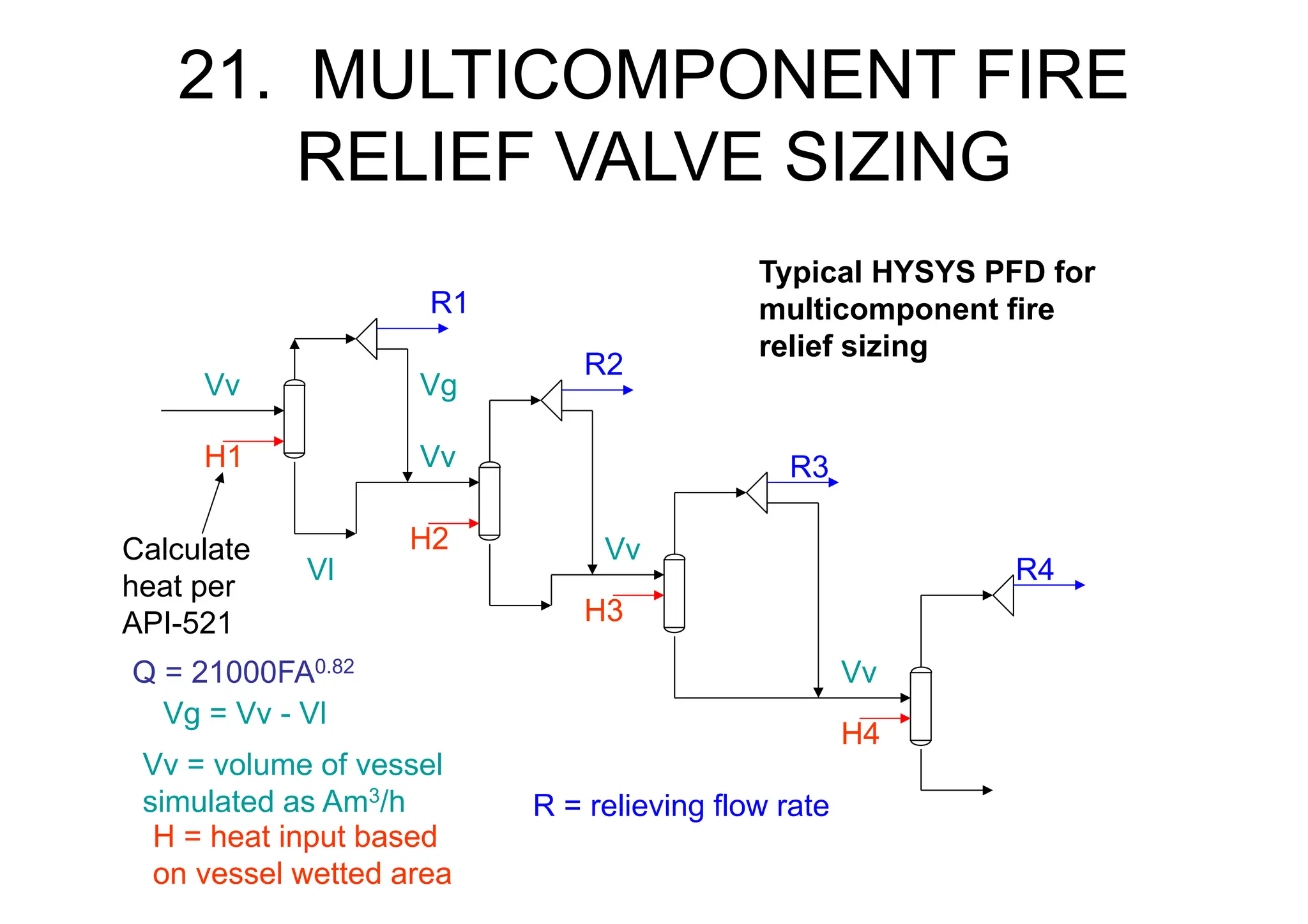
• Fire relief for multicomponent mixtures, you can
use HYSYS. If you can’t use dynamic simulation,
then simulate the fire as a series of flashes,
inputting heat calculated per API-521, separate
gas and liquid, split the gas stream and make
one split actual volume equal to the gas volume
in the vessel. The other stream is the relief
stream for that flash. Use the highest flow as the
size determining flow
22.
21. MULTICOMPONENT FIRE
RELIEFVALVE SIZING
H1
H2
H3
H4
Calculate
heat per
API-521
R1
R2
R3
R4
Vv
Vv
Vv
Vv
Vv = volume of vessel
simulated as Am3/h
H = heat input based
on vessel wetted area
R = relieving flow rate
Typical HYSYS PFD for
multicomponent fire
relief sizing
Q = 21000FA0.82
Vg = Vv - Vl
Vl
Vg
23.
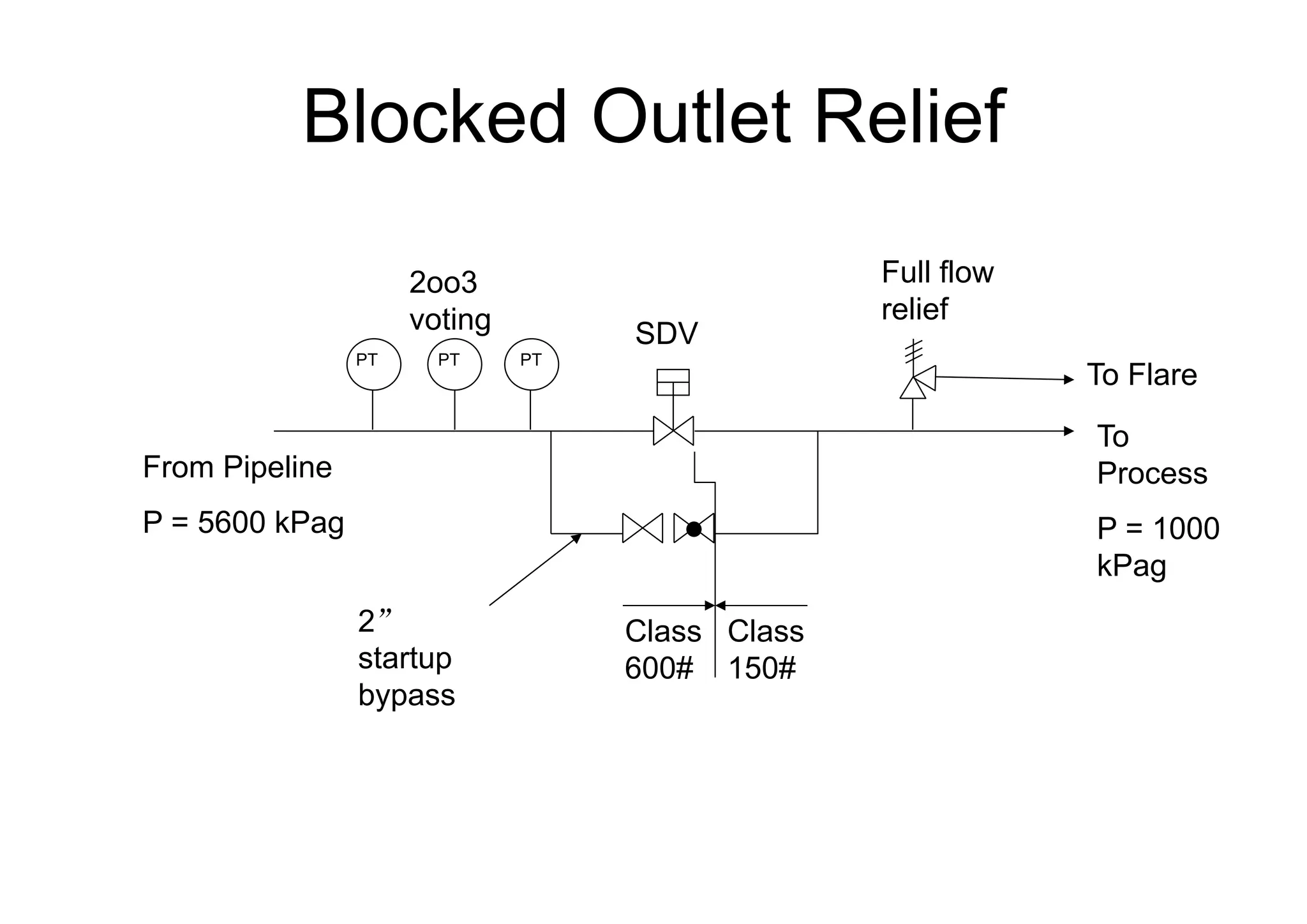
Blocked Outlet Relief
FromPipeline
P = 5600 kPag
PT PT PT
Class
600#
Class
150#
Full flow
relief
To Flare
To
Process
P = 1000
kPag
2”
startup
bypass
2oo3
voting SDV
24.
22. GAS DISPERSIONAND
FLARE RADIATION
• Done so height/position of the flare or vent
stack in relation to operating areas can be
determined
• Gas dispersion - maximum gas concentration
in working areas < 25% of the LEL to ensure
prevention of vent ignition
• If ignited, radiation levels should not exceed
those defined in API-521 (Table 8)
• To do these calcs, you can use Cirrus which
is available free of charge from B.P.
25.
23. DRAWINGS -P&IDs
• Use Distribution Drawings for Utilities
• Lines going from one drawing to the
next is messy. Neater to use a
distribution drawing.
• Use a check list when checking
P&IDs
• Ensure that Fonts are consistent
• When modifying plant, use
“Demolition Drawings” to show
removed equipment and lines
26.
24. CONTROLLING THE
PROCESS
•Use the KISS principal when designing
control systems
• Offshore process - simple
• In most cases, control systems are simple
• Pressure controlled in the Production Sep
• Flow controlled manually on well chokes
• Flow to WI Wells is by flow or pressure
• High pressure override can be used on WI
wells to guard against well fracturing – use
a signal selector
27.
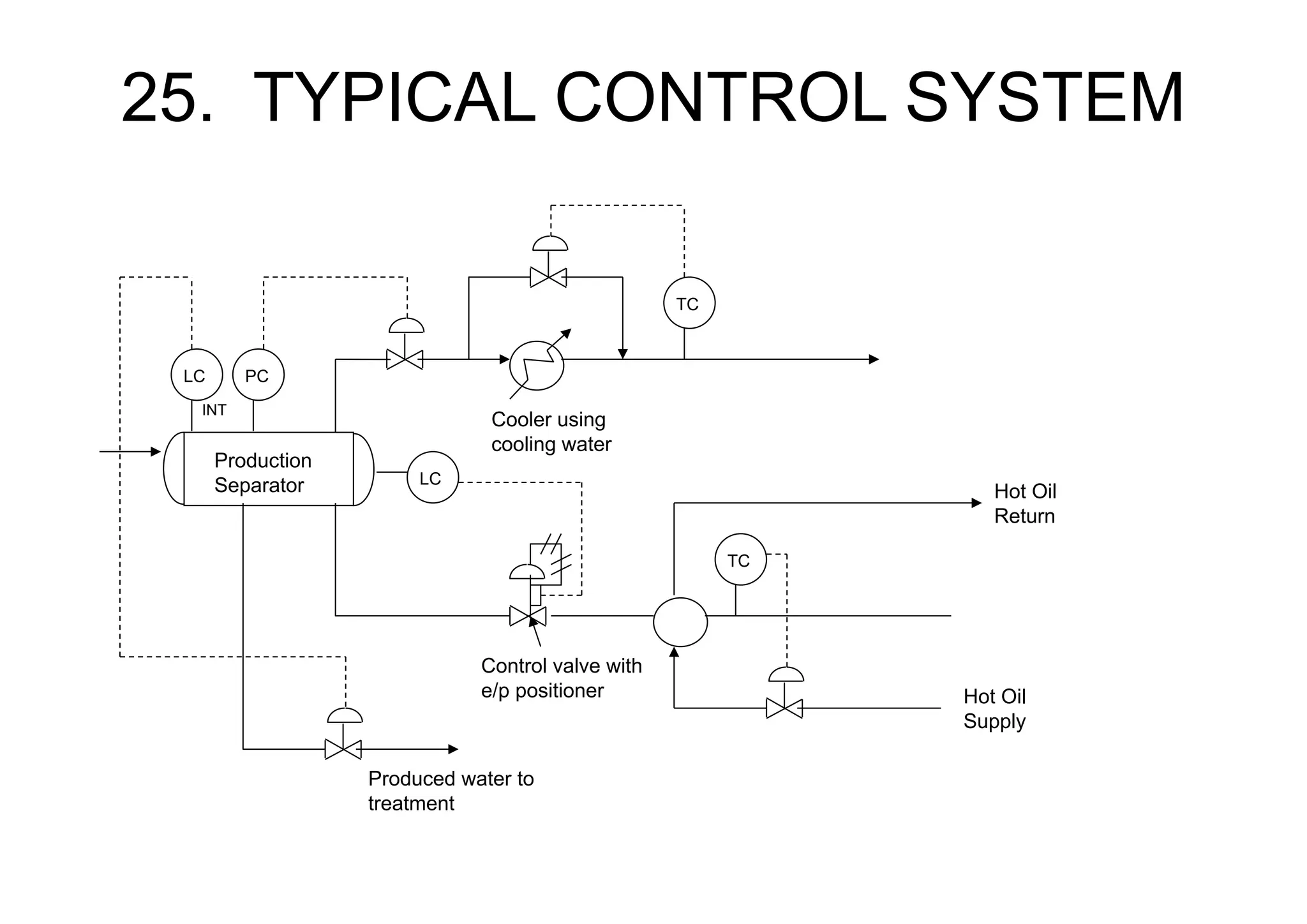
25. TYPICAL CONTROLSYSTEM
Production
Separator
PC
LC
TC
Cooler using
cooling water
TC
Hot Oil
Supply
Hot Oil
Return
Produced water to
treatment
LC
Control valve with
e/p positioner
INT
28.
26. HOMEWORK
TC
Cooling water
Supply
ProcessFluid
Process Cooler
TV
Cooling water
Return
Question:
The exchanger outlet temperature is controlled by bypassing hot process fluid around the heat
exchanger. Cooling water flow rate is constant.
1. What is a possible problem in sizing the control valve? What is the approximate expected maximum
process turndown achievable with this design? How can it be improved?
2. What things will affect the sizing of this control valve i.e. what things will affect the required flow rate
through this valve? 2b. What determines maximum flow through this valve?
3. If this is a gas exchanger, is there anything else we need to be careful of with this control system?
4. What if it is a waxy oil exchanger?
To Flare
29.
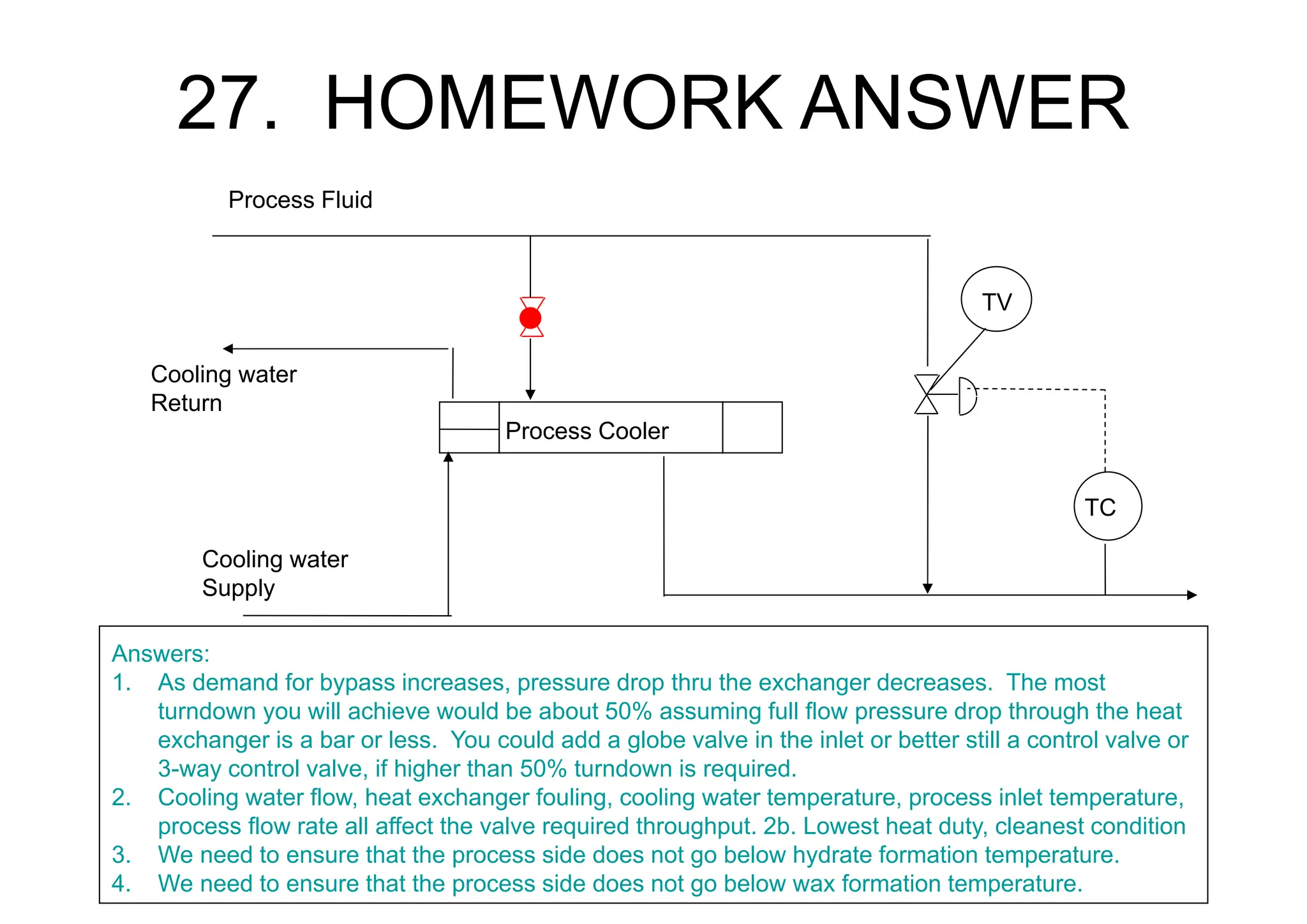
27. HOMEWORK ANSWER
TC
Coolingwater
Supply
Process Fluid
Process Cooler
TV
Cooling water
Return
Answers:
1. As demand for bypass increases, pressure drop thru the exchanger decreases. The most
turndown you will achieve would be about 50% assuming full flow pressure drop through the heat
exchanger is a bar or less. You could add a globe valve in the inlet or better still a control valve or
3-way control valve, if higher than 50% turndown is required.
2. Cooling water flow, heat exchanger fouling, cooling water temperature, process inlet temperature,
process flow rate all affect the valve required throughput. 2b. Lowest heat duty, cleanest condition
3. We need to ensure that the process side does not go below hydrate formation temperature.
4. We need to ensure that the process side does not go below wax formation temperature.
30.
28. TEMPERATURE CONTROL
•Heating is used on platforms to stabilize
crude and break emulsions – temperature
controlled by adjusting heat medium flow
• For Sea Water Coolers – use a hot
process bypass. Do not control water flow
• Keep cooling water velocities > 1.2 m/s
• Keep cooling water temperature < 48ºC to
prevent calcium salts scale (reverse sol)
31.
29. LEVEL CONTROL
•Various level controllers are used
• For heavy waxy emulsion forming
crudes, profilers can be used to
control level
• If S.G. is constant, a bubbler, dP or
pressure transmitter (for atmospheric
tanks) can be used.
• Other types – displacers, capacitance,
ultrasonic
32.
30. MORE COMPLEXCONTROL
• Design out Process upsets
using controls
• Upsets can cause shutdown
• Aim of Operators is to keep
plant running -design
accordingly
• Homework problem
33.
31. TEG UNITS
Q1.What can go wrong with this
control system design? (Hint:
What happens if one TEG Train
shuts down
Q2. What controls can be added
to solve the problem?
QUESTIONS
PC
PC
PC
From Gas
Production Wells
Production
Separator
Filter
Separator
Gas
Cooler
To Flare
TEG
Contactor
FT
FT
Set @
11,700
kPag
34.
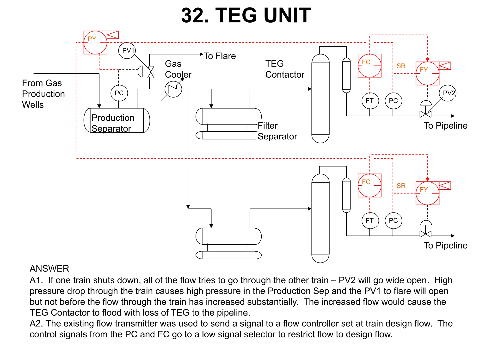
32. TEG UNIT
A1.If one train shuts down, all of the flow tries to go through the other train – PV2 will go wide open. High
pressure drop through the train causes high pressure in the Production Sep and the PV1 to flare will open
but not before the flow through the train has increased substantially. The increased flow would cause the
TEG Contactor to flood with loss of TEG to the pipeline.
A2. The existing flow transmitter was used to send a signal to a flow controller set at train design flow. The
control signals from the PC and FC go to a low signal selector to restrict flow to design flow.
ANSWER
PC
PC
From Gas
Production
Wells
Production
Separator Filter
Separator
Gas
Cooler
To Flare
TEG
Contactor
FT
FC
FY
PC
FT
FC
FY
PV1
PV2
To Pipeline
To Pipeline
SR
SR
PY
35.
33. SYSTEMS
• processsystem and the Utility Systems
• process consists of a number of discrete
systems that interact with each other
• utility systems provide infrastructure to the
process system that allows it to operate
• Utility Systems include:
Utility and Instr. Air, Cooling Medium, Heating
Medium, Open Drains, Closed Drains, Relief and
Blowdown System, Sea Water, Fresh Water,
Fuel Gas, Diesel, Fuel Oil, Chem. Injection,
Electric Power, Fire Water System (not really
utility)
36.
34. UTILITY ANDINSTRUMENT
AIR
• Utility air - air driven tools and equipment
• Instrument air is filtered and dried utility air
• Instr. Air is used to drive control valve,
SDVs and BDV actuators.
• SDVs and BDVs are fail safe
• SDVs generally fail closed
• BDVs generally fail open
• BDVs and SDVs are actuated by failsafe
solenoid vavles
37.
35. AIR COMPRESSORSAND
DRYERS
• Air is filtered, compressed, cooled,
separated and stored in the Utility Air
Receiver (buffer for Instrument and Utility
Air System)
• Air for instruments is filtered, dried, filtered
again stored in a Receiver then distributed
• Air compressors normally 2 x 100%
operating in duty standby mode
• Instrument air normally 700 kPag
• Air compressors discharge at 1100 kPag
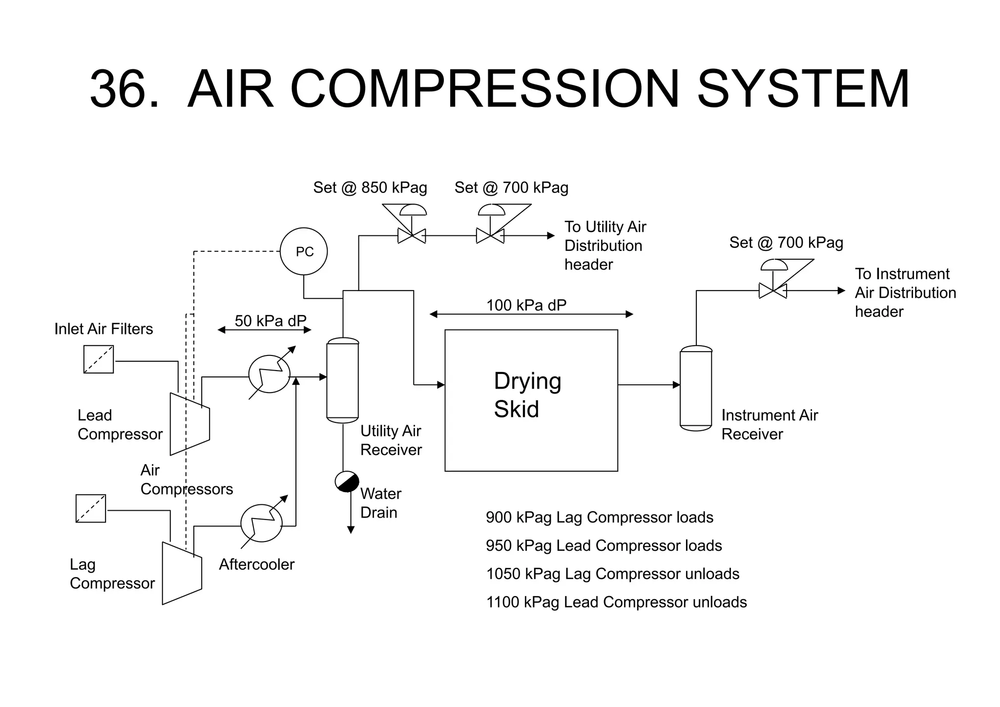
38.
36. AIR COMPRESSIONSYSTEM
Drying
Skid
Utility Air
Receiver
Instrument Air
Receiver
Water
Drain
Air
Compressors
Aftercooler
Lead
Compressor
Lag
Compressor
900 kPag Lag Compressor loads
950 kPag Lead Compressor loads
1050 kPag Lag Compressor unloads
1100 kPag Lead Compressor unloads
Set @ 700 kPag
Set @ 700 kPag
Set @ 850 kPag
100 kPa dP
50 kPa dP
Inlet Air Filters
PC
To Instrument
Air Distribution
header
To Utility Air
Distribution
header
39.
37. INSTRUMENT AIR(cont.)
• The Compressor flow rate must account
for Dryer regeneration air
• Compressor sized on basis of maximum
continuous instrument air requirement
• Receivers are sized to give at least 15
minutes plant operation with the
compressors shut down
40.
38. COOLING MEDIUM
•cooling water (sea water), air (fin-fan cooling),
or secondary medium cooled by sea water
• In China we use direct Sea Water Cooling
• special materials are needed for piping and
exchangers – monel, titanium, hastelloy C etc.
• Piping is duplex, cunifer, plastic (GRP)
• If plastic pipe is used, pump discharges
normally metal to protect plastic against
shock and vibration
41.
39. HEATING MEDIUM
•In China, thermal oils (Hot Oils) are used
• Heat source - Fired heaters or waste heat
• Expansion Vessel – sized to allow
expansion due to density difference
between cold and hot oil.
• Expansion vessel can be run hot or cold
• Expansion Vessel requires blanketing
• Pumps – preferably to give hot oil
pressure > process pressure
42.
40. HEAT MEDIUMSYSTEM
(cont.)
• System Design Pressure – consider tube
rupture case. Increase Des P to avoid this
• Hot Oil heaters – fired by waste heat with
supplemental duct burners.
• Radiant heaters – keep skin temperatures
below thermal oil degradation temp.
• Fuel – gas, crude oil, diesel (start-up or
emergencies only)
43.
41. TYPICAL HOTOIL SYSTEM
Process
Stream
TC
TV
TC FC
From Fuel
Gas
Expansion
Vessel
Hot Oil
Heater
To Flare
From
Fuel Gas
Hot Oil
Circulation
Pumps
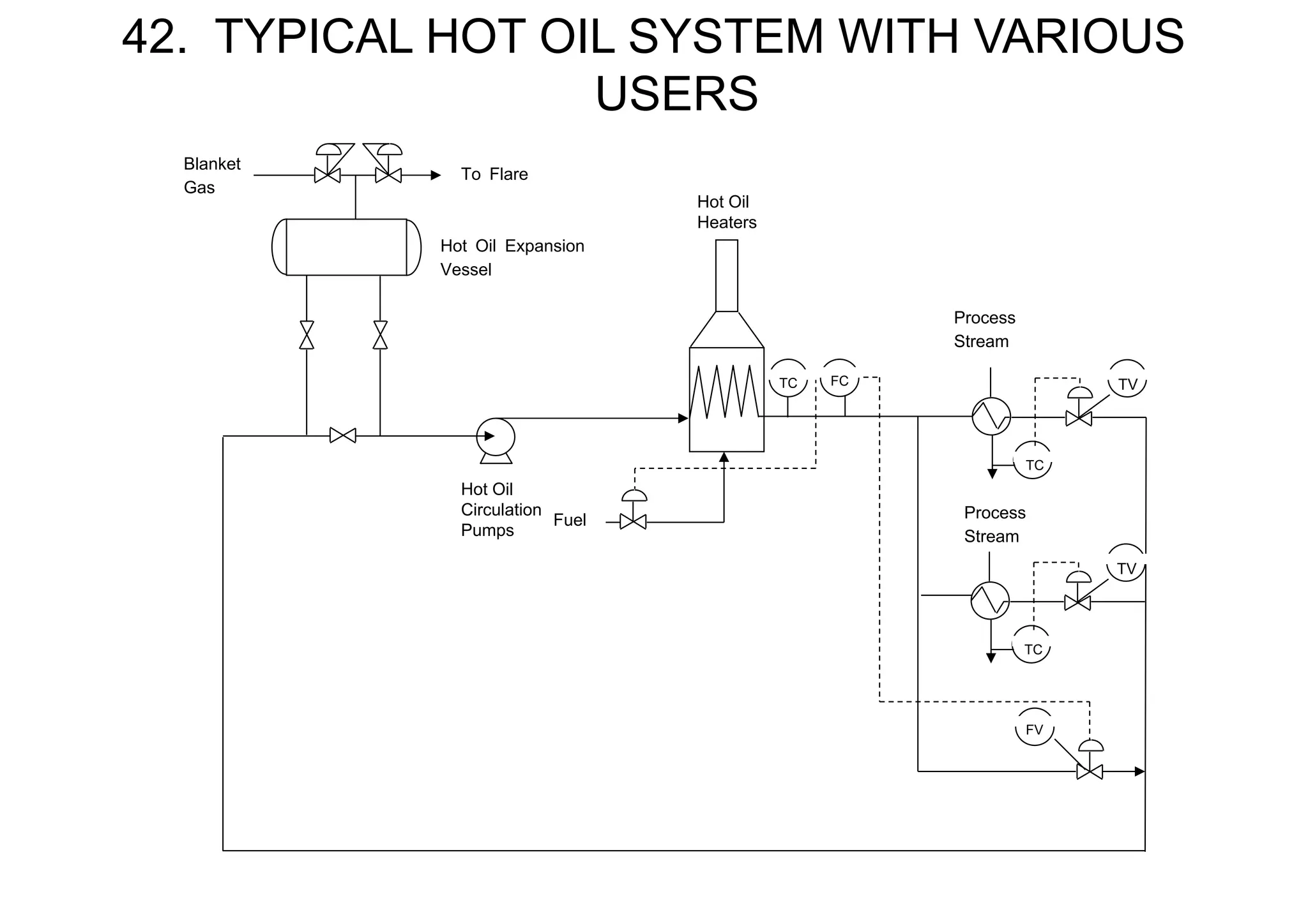
44.
42. TYPICAL HOTOIL SYSTEM WITH VARIOUS
USERS
TC
Process
Stream
TV
Process
Stream
Hot Oil Expansion
Vessel
Blanket
Gas
To Flare
Hot Oil
Circulation
Pumps
Hot Oil
Heaters
Fuel
FC
TC
TC
TV
FV
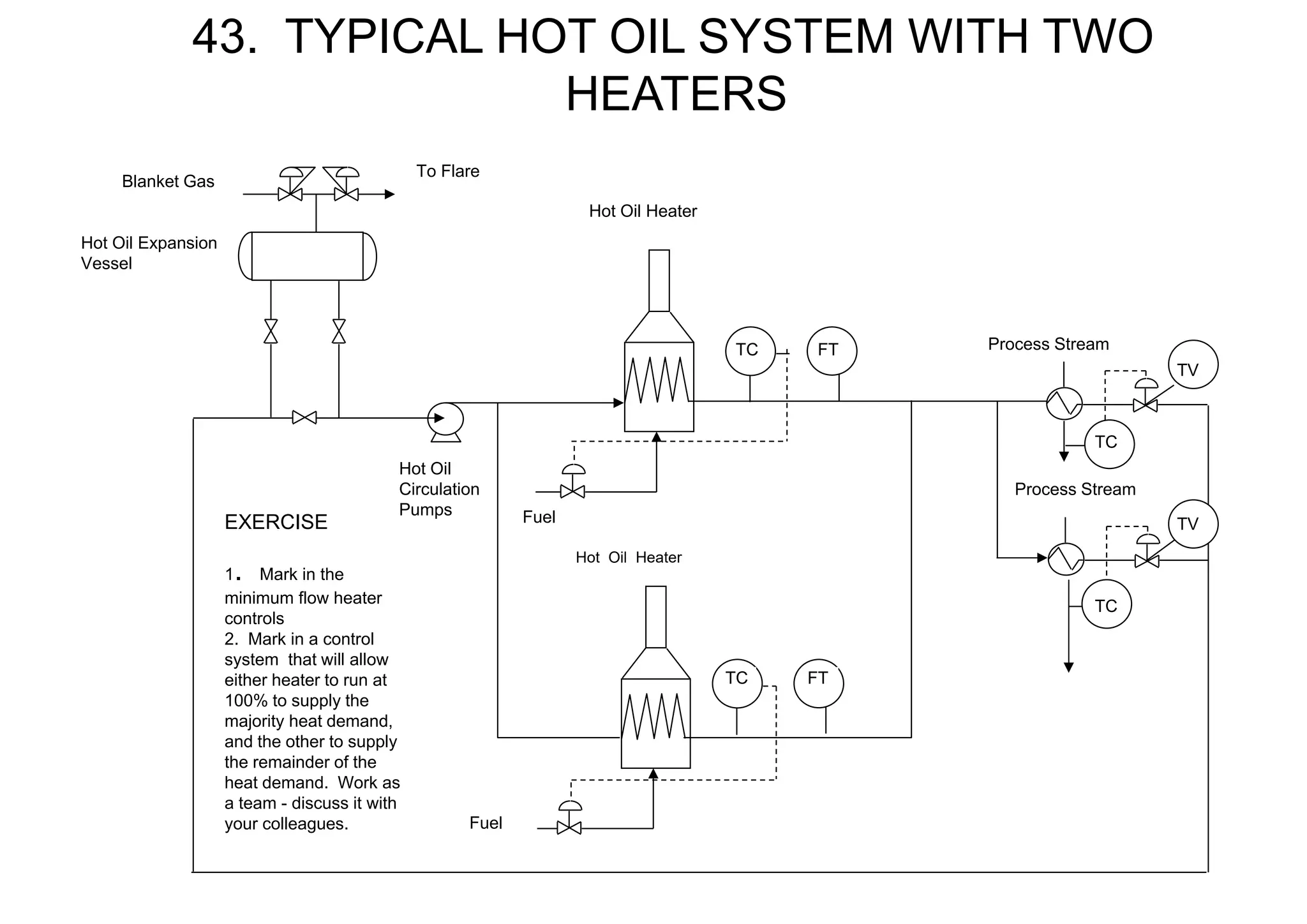
45.
43. TYPICAL HOTOIL SYSTEM WITH TWO
HEATERS
EXERCISE
1. Mark in the
minimum flow heater
controls
2. Mark in a control
system that will allow
either heater to run at
100% to supply the
majority heat demand,
and the other to supply
the remainder of the
heat demand. Work as
a team - discuss it with
your colleagues.
Hot Oil Expansion
Vessel
Blanket Gas
To Flare
Hot Oil
Circulation
Pumps
Hot Oil Heater
Fuel
Hot Oil Heater
Fuel
Process Stream
Process Stream
TV
TV
FT
TC FT
TC
TC
TC
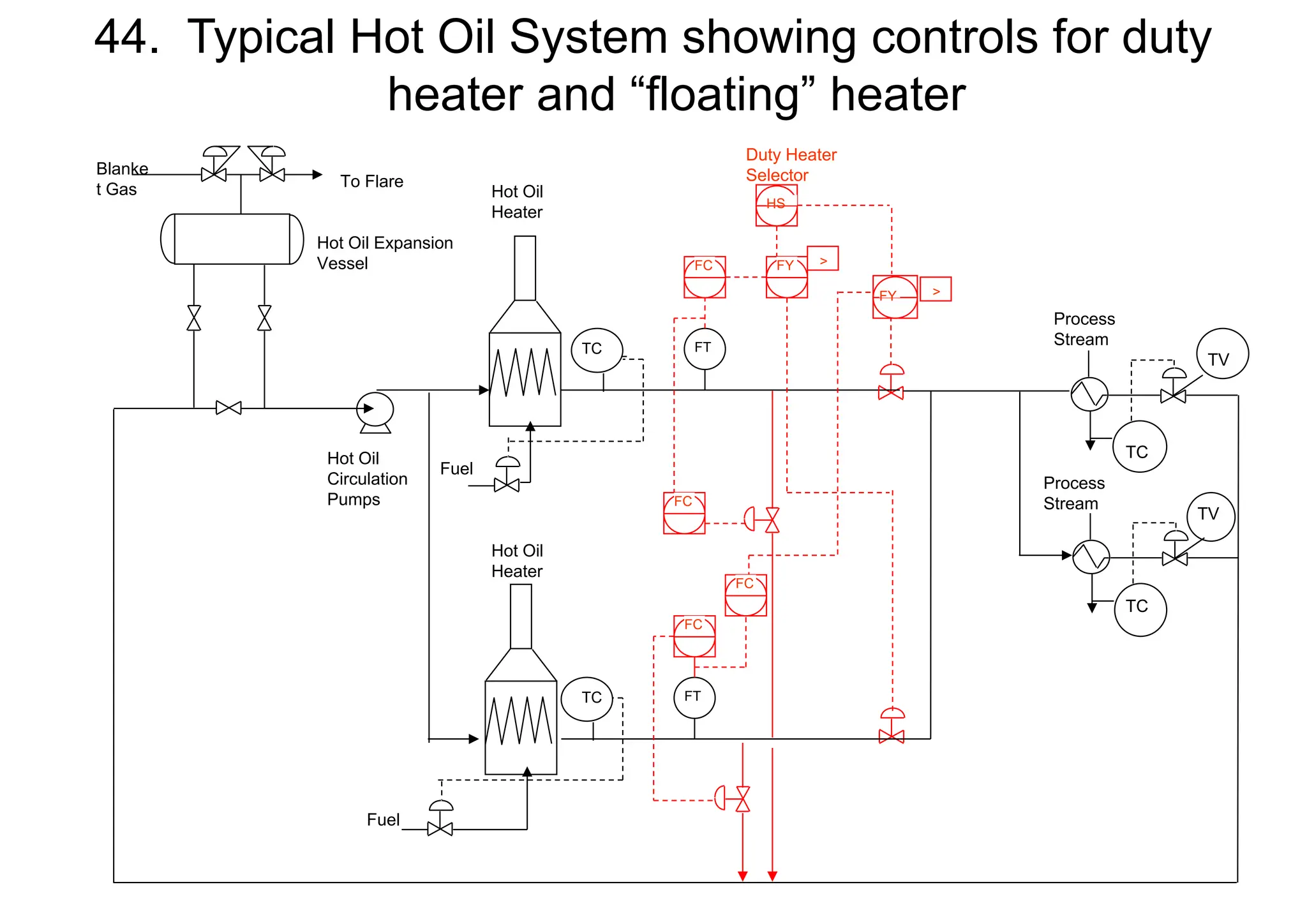
46.
44. Typical HotOil System showing controls for duty
heater and “floating” heater
TV
Process
Stream
Process
Stream
Hot Oil Expansion
Vessel
Blanke
t Gas To Flare
Hot Oil
Circulation
Pumps
Hot Oil
Heater
TC
Fuel
Hot Oil
Heater
Fuel
HS
FY
Duty Heater
Selector
TC
FC FY
FC
FC
FC
FT
FT
>
>
TC
TC
TV
TV
47.
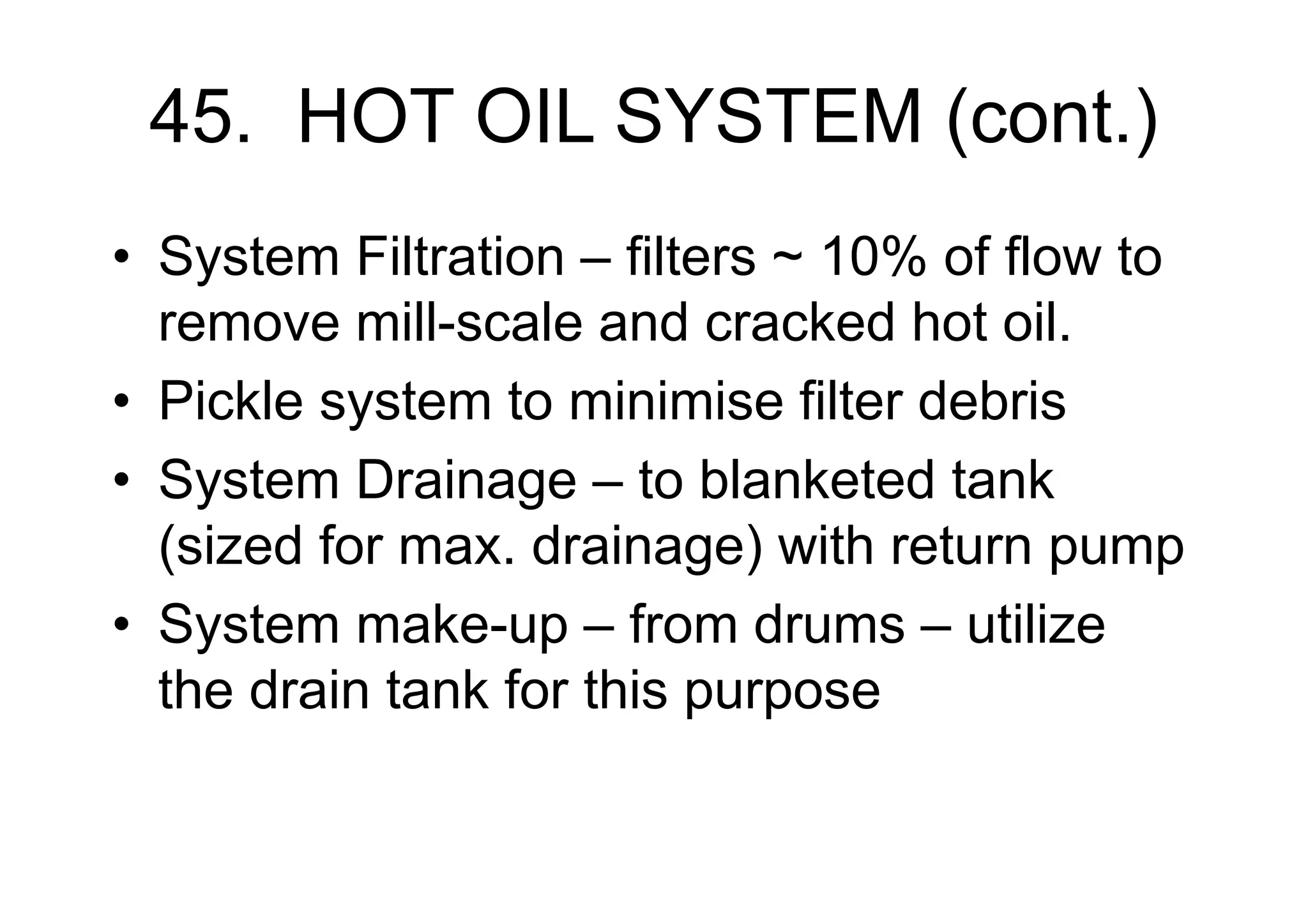
45. HOT OILSYSTEM (cont.)
• System Filtration – filters ~ 10% of flow to
remove mill-scale and cracked hot oil.
• Pickle system to minimise filter debris
• System Drainage – to blanketed tank
(sized for max. drainage) with return pump
• System make-up – from drums – utilize
the drain tank for this purpose
48.
46. HOT WATERSYSTEM
• Similar to Hot Oil except the system
pressure is controlled and the hot water
is saturated
• The Surge tank is the highest point in
the system to ensure the water in the
rest of the system is below the
saturation temperature
49.
46a HOT WATERSYSTEM
PC
TV
TC
From Fuel
Gas
Surge
Vessel
Hot Water
Heater
Hot Water
Circulation
Pumps
Users
Distribution Header
Process
Stream
Surge Vessel at highest
point in system
PV
PC


![[BROCHURE] Italy Tour Project | @SlideON](https://cdn.slidesharecdn.com/ss_thumbnails/brochure8-251215152319-2805af68-thumbnail.jpg?width=640&height=640&fit=bounds)


