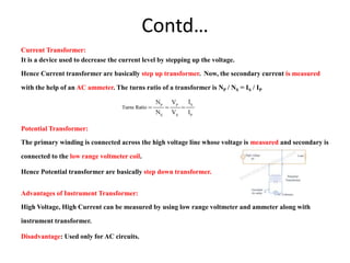
18-Dec-23 Micro 8051 1
Course Title:
POWER SYSTEM PROTECTION
Subject Code:18EE72
Course by
Mr. A.Velu M.Tech (Ph.D)
Assistant Professor
Department of Electrical and Electronics Engineering
Rajeev Institute of Technology,Hassan-573201,Karnataka,India
TEXT BOOK:
 Power System Protection and Switchgear, Badri Ram,
D.N.Vishwakarma, McGraw Hill, 2nd Edition.
18-Dec-23 Micro 8051 2
Module 1
INTRODUCTION TO POWER SYSTEM
PROTECTION
An Electric Power System Consists of
 Generation
 Transmission
 Distribution
18-Dec-23 Micro 8051 3
Structure of Power System
Components of an Electric Power System
CONTROL EQUIPMENT
Need for Protective Schemes
• If a fault occurs in an element of a power system, an automatic protective
device is needed to isolate the faulty element as quickly as possible to keep the
healthy section of the system in normal operation.
• Due to heavy short circuit the system voltage may reduce to a low level and
individual generators in a power station or group of generators in different
power stations may lose synchronism. Thus, an uncleared heavy short circuit
may cause the total failure of the system
• A protective scheme includes circuit breakers and protection relays to isolate
the faulty section of the system from the healthy section.
• The function of a protective relay is to detect and locate a fault and issue a
command to the circuit breaker to disconnect the faulty element of the system.
Contd…
• Protection is needed not only against short circuits but also against any
other abnormal conditions which may arise on a power system.
• A few example of other abnormal conditions are over speed of generators
and motors over-voltage, under-frequency, loss of excitation overheating of
stator and rotor of an alternator etc.
• Protective relays are also provided to detect such abnormal conditions and
issue alarm signals to alert operators or trip circuit breaker.
• A protective relay does not anticipate or prevent the occurrence of a fault,
rather it takes action only after a fault has occurred. However one exception
to this Buchholz relay, a gas actuated relay, which is used for the protection
of power transformers.
NATURE AND CAUSES OF FAULTS
• Faults are caused either by insulation failures or by conducting path
failures.
• The failure of insulation results in short circuits which are very harmful as
they may damage some equipment of the power system.
• Most of the faults on transmission and distribution lines are caused by
overvoltage due to lightning or Switching surges or by external conducting
object falling on overhead lines.
• Over voltages due to lighting or switching surges cause flashover on the
surface of insulators resulting in short circuits.
• Short circuits are also caused by tree, branches or other conducting objects
falling on the overhead lines which leads to the failure of conducting path.
Contd…
• Unbalanced currents flowing in rotating machines set up harmonics,
thereby heating the machines in short periods of time.
• Other causes of faults on overhead lines are: direct lightning strokes,
aircraft, snakes, ice and snow loading, abnormal loading, storms,
earthquakes, creepers., etc.
• In case of cables , transformers,generators and other equipment, the cause
of faults are: failure of the solid insulation due to aging, heat, moisture or
overvoltage, mechanical damage, accidental contact with earth or earthed
screens, flashover due to over voltages etc.
CONSEQUENCES OF FAULT
• Flashover on Insulators: Sometimes insulators gets punctured or break ,
even sometimes certain foreign particles such as fine cement,dust or soot in
industrial areas or salt in coastal areas or any dirt in general accumulates on
the surface of string and pin insulators. This reduces the insulation
strengths and causes flashover.
• Failure of conducting Path: Birds also may cause faults on overhead lines if
their bodies one of the phases and the earth wire. If the conductors are
broken, there is a failure of the conducting path and the conductor becomes
open circuited.
• Unbalanced System: The opening of one or more of the three phases
makes the system unbalanced. The unbalanced current leads to set up
harmonics which is not allowed in the normal operation of a power system.
TYPES OF FAULTS
Two broad classification of faults , are
i) Symmetrical faults
ii) Unsymmetrical faults
Symmetrical faults:
A three-phase (3-ϕ) fault is called a Symmetrical type of faults.
In a (3-ϕ) fault all the three phases may be short circuited.
There may be two situations -all the three phases may be short circuited to the
ground or they may be short-circuited without involving the ground.
A (3-ϕ) short circuit is generally treated as a standard fault to determine the
system fault level.
Contd…
Unsymmetrical Faults
Contd…
Contd…
EFFECT OF FAULTS
Contd…
Contd…
Zones Of Protection
Primary and Backup protection
• The protection provided by the protective relaying equipment can be
categorized into two types as
Primary protection
Backup Protection
The primary protection is the first line of defense and is responsible to protect
all the power system elements from all the types of faults.
The backup protection comes into play only when the primary protection fails.
The backup protection is provided as the main protection can fail due to many
reasons like 1.Failure in circuit breaker 2.Failure in Protective relay 3.Failure
in tripping circuit 4.Failure in d.c tripping voltage 5.Loss of voltage or current
supply to the relay.
Thus if the backup protection is absent and the main protection fails then there
is possibilities of serve damage to the system.
Contd…
• When the primary protection is made inoperative for the maintenance
purpose, the backup protection acts like a main protection.
• Backup relay operates after a time delay to give the primary relay sufficient
time to operate.
• As far as possible a backup relay should be placed at a different station.
Sometime a local back up is also used.
• . There are 3 types backup relays.
Remote backup
Relay Backup
Breaker Backup
When a fault occurs on power system, only faulty part should be isolated. No healthy part
of the system should be deprived of electric supply should be left intact.
Due to Switching transients, voltage in the line increase drastically, it shouldn’t
unnecessary trip the relay circuit because it will be present only short period of
time. The relay should also be able to discriminate between a fault and transient
conditions like power surges or inrush of a transformer’s magnetizing current.
Performance of Protective Relaying
• When a fault occurs in a particular zone of the power system, the primary relays of
that zone are expected to operate and initiate isolation of the faulty element.
• However, back -up relay surrounding that area are also alerted by the fault and
begin to operate. They do not initiate tripping if the primary relays operate
correctly.
• The back-up relay operates, if due to any reason the primary relay fails to operate.
• Though several primary relay are employed in many protection systems but
frequently only one of the relays actually initiates tripping of the circuit breaker.
• There may be no direct evidence regarding the other relays being in a correct
operating mode.
Contd…
The performance of the protective relay is documented by those relays that provide direct or
specific evidence of operation.
Relay performance is generally classified as
• Correct operation
• Incorrect operation
• No conclusion
Correct Operation:
The correct operation gives indication about
(i) Correct operation of at least one of the primary relays,
(ii) Operation of none of the back-up relays to trip for the fault, and
(iii) Proper isolation of the trouble area in the expected time.
Almost all relay operation are corrected and wanted, i.e., the operation is as per plan and
programme
Contd…
Incorrect Operation:
• A failure, a malfunction or an unplanned or unanticipated operation of the
protective system results in incorrect operation of the relay.
• The incorrect operation of the relay can cause either incorrect isolation of
an unfaulted area, or a failure to isolate a faulted area.
• The reason for incorrect operation can be any one or a combination of
(i) misapplication of relay,(ii) incorrect setting ,(iii) personnel error ,
and iv) equipment's malfunctions.
• Equipment that can cause an incorrect operation includes CTs,VTs,
relays, breakers, cable and wiring, pilot channels (Communication
Channels), station batteries, etc.
Contd…
No Conclusion:
When one or more relays have or appear to have operated, such as the tripping
of the circuit breaker, but no cause of operation can be found, it is the case of
no conclusion .
Neither any evidence of a power system fault or trouble, nor apparent failure
of the equipment, causes and extremely frustrating situation. Thus the cases of
no conclusion involves considerable concern and thorough investigation.
Electromagnetic Relays:
Attraction Type: Attracted armature type relay operation depends on the
movements of an armature under the influence of attractive force due to
magnetic field set up the current flowing through the relay winding.
Solenoid Type: Solenoid type relay operation depends on the movement of
an iron plunger core along the axis of solenoid.
It is used for both ac and dc.
Electromagnetic Induction type:
This is for only AC.
Movement of a metallic disc or cylinder free to rotate by induced currents and
alternating magnetic fields produced by them.
These fluxes induced in the upper and lower magnetic differs in phase by
angle θ which will develop a driving torque on the disc proportional to φ1φ
sinθ.This torque causes to rotate the disc and moving contacts comes towards
fixed contacts and the trip circuit is completed.
Electro Thermal type:
Relay movement depends on the action of heat produced by the current
flowing through the element of a relay.
This is for both AC and DC.
Solid State Relays
 Introduction
This is latest development in this area.
They are based on numerical devices e.g( Microprocessors,Microcontroller,DSPs
ADVANTAGES:
Limited range of applications attractive flexibility due to their programmable
approach
Low cost.
Over Voltage Relays/Over Current Relays/Over Power Relays
Impedance Relays or Distance Relays: It measure the line impedance
between relay location and point of Fault & operate if the point of faults lies
within protected zone. Z=V/I
Directional Relay or Reverse Current Relays: It check whether point of
fault lies in the forward or reverse direction.
Differential Relays: It takes the difference between two electrical quantities
(magnitude or phase),based on their difference relay will operate.
Under Voltage/Under Current/Under Power Relays
Classification based on Timing Characteristics
• Instantaneous Relay: In this relay, no intentional time delay is introduced to
slow down their response. These relay operate as soon as secure decision is
made.(Typically less than 0.2sec.)
• Definite time lag relay: Operating time is independent of magnitude of
quantity causing operation.(Time lag is fixed).
• Inverse time lag relay: Time of operation will be inversely proportional to
magnitude of quantity.( If the fault current more it will take less time to operate
and vice versa.
• Inverse definite minimum time lag relay(IDMT): Time is inversely
proportional for smaller values of operating quantity and tends to be definite
minimum time as value increases without limit.
Classification based on Speed of operation
• Instantaneous Relay- In these relay, no intentional time is introduced to
slow down their response.
• Time delay relays-In these relay, an intentional time delay is introduced
between the relay decision and the initiation of the trip action.
• High Speed relays-These relay operate less than a specified time.(60
milliseconds)
• Ultra high speed relays-Though this term is not included in the relay
standard but these relays are commonly considered to operate within 5
milliseconds.
Automatic Reclosing
• Automatic reclosing associated with the operation of circuit breaker when the fault is
occurred and clearance of fault.
• About 90% faults on overhead lines are of transient nature.
• Transient faults are caused by lightning, such faults are always associated with arcs.
• If the line is disconnected from the system for a short time, the arc is extinguished and
the fault disappears. Immediately after this, the circuit breaker can be reclosed
automatically to restore the supply.
• Most faults in EHV lines are caused by lightning. Hence instantaneous reclosure is used
in case of EHV lines.
• On lines up to 33KV, most faults caused by external objects falling on overhead lines.
Contd…
• Usually three reclosures at 15-120 seconds intervals are made to clear the
fault.
• Statistical reports shows that over 80% faults are cleared after the first
reclosure.
• 10% require the second reclosure
• 2% need the third reclosure.
• Remaining 8% are permanent faults.
• Automatic reclosure are not used on cables as the breakdown of insulation
in cables causes a permanent fault.
Instrument Transformer
In power system currents & voltages handled are very high and hence direct
measurement with conventional instruments is not possible without compromising
operator safety.
The solution is to step down these currents and voltages with the help of instrument
transformers so that instruments of moderate rating can be used for measurement.
Transformer used in conjunction with measuring instruments for the measurement
purpose are called Instrument Transformer.
The transformer used for measurement of current is called Current Transformer(CT).
The Transformer used for measurement of voltage is called Voltage Transformer or
Potential Transformer(PT )
Instrument transformer are used to
i) To supply protective relays which operate at lower voltages & currents.
ii) Isolate the measuring instrument from a high voltage line.
Contd…
Current Transformer:
It is a device used to decrease the current level by stepping up the voltage.
Hence Current transformer are basically step up transformer. Now, the secondary current is measured
with the help of an AC ammeter. The turns ratio of a transformer is NP / NS = IS / IP
Potential Transformer:
The primary winding is connected across the high voltage line whose voltage is measured and secondary is
connected to the low range voltmeter coil.
Hence Potential transformer are basically step down transformer.
Advantages of Instrument Transformer:
High Voltage, High Current can be measured by using low range voltmeter and ammeter along with
instrument transformer.
Disadvantage: Used only for AC circuits.
Important Terms
 Relay: A Relay is an automatic device by means of which an electrical
circuit is indirectly control(opened or closed) and is governed by a change
in the same or another electric circuit.
or
 The relay is the device that open or closes the contacts to cause the
operation of the other electric control.
 Protective Relay: A Protective Relay is an automatic device which detects
an abnormal condition in an electric circuit and causes a circuit breaker to
isolate faulty element of the system.
 Operating Force or Torque: A force or torque which tends to close the
contacts of the relay.
 Restraining force or Torque: A force or torque which opposes the
operating force/Torque. Or It is a force or torque which opposes the
operating torque and prevents the closure of relay contacts.
 Operating Time:
Time elapsed between the instant when the actuating quantity exceeds the
pickup value to the instant when the relay contacts closes.
 Reset time:
Time elapsed between the instant when the actuating quantity becomes
less than reset value to the instant when the relay returns to its original position.
 Current setting:
It is often desirable to adjust the pick-up current to any required value.
This is known as current setting and is usually achieved by the use of tappings on
the relay operating coil.

Module 1 Power System Protection(18EE72).pptx

  • 1.
    18-Dec-23 Micro 80511 Course Title: POWER SYSTEM PROTECTION Subject Code:18EE72 Course by Mr. A.Velu M.Tech (Ph.D) Assistant Professor Department of Electrical and Electronics Engineering Rajeev Institute of Technology,Hassan-573201,Karnataka,India
  • 2.
    TEXT BOOK:  PowerSystem Protection and Switchgear, Badri Ram, D.N.Vishwakarma, McGraw Hill, 2nd Edition. 18-Dec-23 Micro 8051 2
  • 3.
    Module 1 INTRODUCTION TOPOWER SYSTEM PROTECTION An Electric Power System Consists of  Generation  Transmission  Distribution 18-Dec-23 Micro 8051 3
  • 4.
  • 5.
    Components of anElectric Power System
  • 6.
  • 7.
    Need for ProtectiveSchemes • If a fault occurs in an element of a power system, an automatic protective device is needed to isolate the faulty element as quickly as possible to keep the healthy section of the system in normal operation. • Due to heavy short circuit the system voltage may reduce to a low level and individual generators in a power station or group of generators in different power stations may lose synchronism. Thus, an uncleared heavy short circuit may cause the total failure of the system • A protective scheme includes circuit breakers and protection relays to isolate the faulty section of the system from the healthy section. • The function of a protective relay is to detect and locate a fault and issue a command to the circuit breaker to disconnect the faulty element of the system.
  • 8.
    Contd… • Protection isneeded not only against short circuits but also against any other abnormal conditions which may arise on a power system. • A few example of other abnormal conditions are over speed of generators and motors over-voltage, under-frequency, loss of excitation overheating of stator and rotor of an alternator etc. • Protective relays are also provided to detect such abnormal conditions and issue alarm signals to alert operators or trip circuit breaker. • A protective relay does not anticipate or prevent the occurrence of a fault, rather it takes action only after a fault has occurred. However one exception to this Buchholz relay, a gas actuated relay, which is used for the protection of power transformers.
  • 9.
    NATURE AND CAUSESOF FAULTS • Faults are caused either by insulation failures or by conducting path failures. • The failure of insulation results in short circuits which are very harmful as they may damage some equipment of the power system. • Most of the faults on transmission and distribution lines are caused by overvoltage due to lightning or Switching surges or by external conducting object falling on overhead lines. • Over voltages due to lighting or switching surges cause flashover on the surface of insulators resulting in short circuits. • Short circuits are also caused by tree, branches or other conducting objects falling on the overhead lines which leads to the failure of conducting path.
  • 10.
    Contd… • Unbalanced currentsflowing in rotating machines set up harmonics, thereby heating the machines in short periods of time. • Other causes of faults on overhead lines are: direct lightning strokes, aircraft, snakes, ice and snow loading, abnormal loading, storms, earthquakes, creepers., etc. • In case of cables , transformers,generators and other equipment, the cause of faults are: failure of the solid insulation due to aging, heat, moisture or overvoltage, mechanical damage, accidental contact with earth or earthed screens, flashover due to over voltages etc.
  • 11.
    CONSEQUENCES OF FAULT •Flashover on Insulators: Sometimes insulators gets punctured or break , even sometimes certain foreign particles such as fine cement,dust or soot in industrial areas or salt in coastal areas or any dirt in general accumulates on the surface of string and pin insulators. This reduces the insulation strengths and causes flashover. • Failure of conducting Path: Birds also may cause faults on overhead lines if their bodies one of the phases and the earth wire. If the conductors are broken, there is a failure of the conducting path and the conductor becomes open circuited. • Unbalanced System: The opening of one or more of the three phases makes the system unbalanced. The unbalanced current leads to set up harmonics which is not allowed in the normal operation of a power system.
  • 12.
    TYPES OF FAULTS Twobroad classification of faults , are i) Symmetrical faults ii) Unsymmetrical faults Symmetrical faults: A three-phase (3-ϕ) fault is called a Symmetrical type of faults. In a (3-ϕ) fault all the three phases may be short circuited. There may be two situations -all the three phases may be short circuited to the ground or they may be short-circuited without involving the ground. A (3-ϕ) short circuit is generally treated as a standard fault to determine the system fault level.
  • 13.
  • 14.
  • 15.
  • 16.
  • 17.
  • 18.
  • 20.
  • 22.
    Primary and Backupprotection • The protection provided by the protective relaying equipment can be categorized into two types as Primary protection Backup Protection The primary protection is the first line of defense and is responsible to protect all the power system elements from all the types of faults. The backup protection comes into play only when the primary protection fails. The backup protection is provided as the main protection can fail due to many reasons like 1.Failure in circuit breaker 2.Failure in Protective relay 3.Failure in tripping circuit 4.Failure in d.c tripping voltage 5.Loss of voltage or current supply to the relay. Thus if the backup protection is absent and the main protection fails then there is possibilities of serve damage to the system.
  • 23.
    Contd… • When theprimary protection is made inoperative for the maintenance purpose, the backup protection acts like a main protection. • Backup relay operates after a time delay to give the primary relay sufficient time to operate. • As far as possible a backup relay should be placed at a different station. Sometime a local back up is also used. • . There are 3 types backup relays. Remote backup Relay Backup Breaker Backup
  • 25.
    When a faultoccurs on power system, only faulty part should be isolated. No healthy part of the system should be deprived of electric supply should be left intact. Due to Switching transients, voltage in the line increase drastically, it shouldn’t unnecessary trip the relay circuit because it will be present only short period of time. The relay should also be able to discriminate between a fault and transient conditions like power surges or inrush of a transformer’s magnetizing current.
  • 28.
    Performance of ProtectiveRelaying • When a fault occurs in a particular zone of the power system, the primary relays of that zone are expected to operate and initiate isolation of the faulty element. • However, back -up relay surrounding that area are also alerted by the fault and begin to operate. They do not initiate tripping if the primary relays operate correctly. • The back-up relay operates, if due to any reason the primary relay fails to operate. • Though several primary relay are employed in many protection systems but frequently only one of the relays actually initiates tripping of the circuit breaker. • There may be no direct evidence regarding the other relays being in a correct operating mode.
  • 29.
    Contd… The performance ofthe protective relay is documented by those relays that provide direct or specific evidence of operation. Relay performance is generally classified as • Correct operation • Incorrect operation • No conclusion Correct Operation: The correct operation gives indication about (i) Correct operation of at least one of the primary relays, (ii) Operation of none of the back-up relays to trip for the fault, and (iii) Proper isolation of the trouble area in the expected time. Almost all relay operation are corrected and wanted, i.e., the operation is as per plan and programme
  • 30.
    Contd… Incorrect Operation: • Afailure, a malfunction or an unplanned or unanticipated operation of the protective system results in incorrect operation of the relay. • The incorrect operation of the relay can cause either incorrect isolation of an unfaulted area, or a failure to isolate a faulted area. • The reason for incorrect operation can be any one or a combination of (i) misapplication of relay,(ii) incorrect setting ,(iii) personnel error , and iv) equipment's malfunctions. • Equipment that can cause an incorrect operation includes CTs,VTs, relays, breakers, cable and wiring, pilot channels (Communication Channels), station batteries, etc.
  • 31.
    Contd… No Conclusion: When oneor more relays have or appear to have operated, such as the tripping of the circuit breaker, but no cause of operation can be found, it is the case of no conclusion . Neither any evidence of a power system fault or trouble, nor apparent failure of the equipment, causes and extremely frustrating situation. Thus the cases of no conclusion involves considerable concern and thorough investigation.
  • 32.
    Electromagnetic Relays: Attraction Type:Attracted armature type relay operation depends on the movements of an armature under the influence of attractive force due to magnetic field set up the current flowing through the relay winding. Solenoid Type: Solenoid type relay operation depends on the movement of an iron plunger core along the axis of solenoid. It is used for both ac and dc.
  • 34.
    Electromagnetic Induction type: Thisis for only AC. Movement of a metallic disc or cylinder free to rotate by induced currents and alternating magnetic fields produced by them. These fluxes induced in the upper and lower magnetic differs in phase by angle θ which will develop a driving torque on the disc proportional to φ1φ sinθ.This torque causes to rotate the disc and moving contacts comes towards fixed contacts and the trip circuit is completed. Electro Thermal type: Relay movement depends on the action of heat produced by the current flowing through the element of a relay. This is for both AC and DC.
  • 35.
  • 41.
    This is latestdevelopment in this area. They are based on numerical devices e.g( Microprocessors,Microcontroller,DSPs ADVANTAGES: Limited range of applications attractive flexibility due to their programmable approach Low cost.
  • 42.
    Over Voltage Relays/OverCurrent Relays/Over Power Relays Impedance Relays or Distance Relays: It measure the line impedance between relay location and point of Fault & operate if the point of faults lies within protected zone. Z=V/I Directional Relay or Reverse Current Relays: It check whether point of fault lies in the forward or reverse direction. Differential Relays: It takes the difference between two electrical quantities (magnitude or phase),based on their difference relay will operate. Under Voltage/Under Current/Under Power Relays
  • 43.
    Classification based onTiming Characteristics • Instantaneous Relay: In this relay, no intentional time delay is introduced to slow down their response. These relay operate as soon as secure decision is made.(Typically less than 0.2sec.) • Definite time lag relay: Operating time is independent of magnitude of quantity causing operation.(Time lag is fixed). • Inverse time lag relay: Time of operation will be inversely proportional to magnitude of quantity.( If the fault current more it will take less time to operate and vice versa. • Inverse definite minimum time lag relay(IDMT): Time is inversely proportional for smaller values of operating quantity and tends to be definite minimum time as value increases without limit.
  • 44.
    Classification based onSpeed of operation • Instantaneous Relay- In these relay, no intentional time is introduced to slow down their response. • Time delay relays-In these relay, an intentional time delay is introduced between the relay decision and the initiation of the trip action. • High Speed relays-These relay operate less than a specified time.(60 milliseconds) • Ultra high speed relays-Though this term is not included in the relay standard but these relays are commonly considered to operate within 5 milliseconds.
  • 45.
    Automatic Reclosing • Automaticreclosing associated with the operation of circuit breaker when the fault is occurred and clearance of fault. • About 90% faults on overhead lines are of transient nature. • Transient faults are caused by lightning, such faults are always associated with arcs. • If the line is disconnected from the system for a short time, the arc is extinguished and the fault disappears. Immediately after this, the circuit breaker can be reclosed automatically to restore the supply. • Most faults in EHV lines are caused by lightning. Hence instantaneous reclosure is used in case of EHV lines. • On lines up to 33KV, most faults caused by external objects falling on overhead lines.
  • 46.
    Contd… • Usually threereclosures at 15-120 seconds intervals are made to clear the fault. • Statistical reports shows that over 80% faults are cleared after the first reclosure. • 10% require the second reclosure • 2% need the third reclosure. • Remaining 8% are permanent faults. • Automatic reclosure are not used on cables as the breakdown of insulation in cables causes a permanent fault.
  • 47.
    Instrument Transformer In powersystem currents & voltages handled are very high and hence direct measurement with conventional instruments is not possible without compromising operator safety. The solution is to step down these currents and voltages with the help of instrument transformers so that instruments of moderate rating can be used for measurement. Transformer used in conjunction with measuring instruments for the measurement purpose are called Instrument Transformer. The transformer used for measurement of current is called Current Transformer(CT). The Transformer used for measurement of voltage is called Voltage Transformer or Potential Transformer(PT ) Instrument transformer are used to i) To supply protective relays which operate at lower voltages & currents. ii) Isolate the measuring instrument from a high voltage line.
  • 48.
    Contd… Current Transformer: It isa device used to decrease the current level by stepping up the voltage. Hence Current transformer are basically step up transformer. Now, the secondary current is measured with the help of an AC ammeter. The turns ratio of a transformer is NP / NS = IS / IP Potential Transformer: The primary winding is connected across the high voltage line whose voltage is measured and secondary is connected to the low range voltmeter coil. Hence Potential transformer are basically step down transformer. Advantages of Instrument Transformer: High Voltage, High Current can be measured by using low range voltmeter and ammeter along with instrument transformer. Disadvantage: Used only for AC circuits.
  • 49.
    Important Terms  Relay:A Relay is an automatic device by means of which an electrical circuit is indirectly control(opened or closed) and is governed by a change in the same or another electric circuit. or  The relay is the device that open or closes the contacts to cause the operation of the other electric control.  Protective Relay: A Protective Relay is an automatic device which detects an abnormal condition in an electric circuit and causes a circuit breaker to isolate faulty element of the system.  Operating Force or Torque: A force or torque which tends to close the contacts of the relay.  Restraining force or Torque: A force or torque which opposes the operating force/Torque. Or It is a force or torque which opposes the operating torque and prevents the closure of relay contacts.
  • 50.
     Operating Time: Timeelapsed between the instant when the actuating quantity exceeds the pickup value to the instant when the relay contacts closes.  Reset time: Time elapsed between the instant when the actuating quantity becomes less than reset value to the instant when the relay returns to its original position.  Current setting: It is often desirable to adjust the pick-up current to any required value. This is known as current setting and is usually achieved by the use of tappings on the relay operating coil.