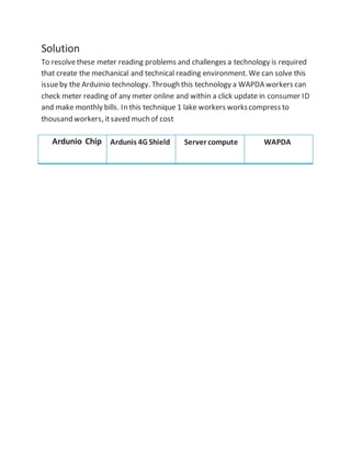
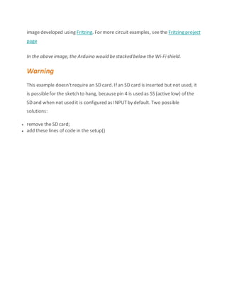
Auto Meter Reading
Submitted by
Sami Ul Haq
Haider Murtaza
MudabirHussain
MuhammadRashid
Waseem Qurashi
Summary
Pakistan is a developing country and they have to face many challenges every day,
in spite of all these challenges they are making progress. WAPDA is the largest
department of Pakistan that are currently facing a bundle of problem. WAPDA
providing electricity energy throughoutthe country and thy have millions of
customer. The major problem that WAPDA is facing to count consumer
consumption or manage the systemof meter reading. Manual reading system
now become old and not be effective even consumer are not satisfied and believe
on manual meter reading. So it is need of time that consumers aredemanding for
any new technology that is trustable and easy to use. Because in manualsystem
not only consumers butalso WAPDA workers feeldifficult and there is many
possibility to damage or mishap this manual record. A technology (auto reading
)in which a WAPDA worker can accesses theelectricity meter of every consumer
and can easily check the current reading and update in his Id. A mechanical and
technical process involved in this technology and someelectro device used. These
devices work in a sequence.
Table of Content
 Problem
Solution
Ardunio
Ardunio 4G Shield
Server
Benefits
Conclusion
Problem
WAPDA is the larger organization and sector of Pakistan that provideenergy to
more than () users. Differentplants founded to meet with energy crises and
overcomethe supply deficit. But WAPDA recording systemhas no worth due to
mismanagement and lack of technology. Mostly it deals with meter reading and
preparation of bills every month. In meter reading process a larger number of
WAPDA worker involved. Workers haveto check each meter reading that is
difficult because total meter are 20 million in number and to check 20 million
meter reading 1 lake workers and it takes moretime and efforts. In many cases
incorrect reading improved due to worker negligence and somecorruption
matters. Sometime meter arefix at height that cause hardly. Govtprovideselfie
stick to take photo of reading but it is providenot much effective In 2014 Govt
make a reading photo systemto avoid incorrect reading that become useless.
Solution
To resolvethese meter reading problems and challenges a technology is required
that create the mechanical and technical reading environment. We can solve this
issueby the Arduinio technology. Through this technology a WAPDA workers can
check meter reading of any meter online and within a click update in consumer ID
and make monthly bills. In this technique 1 lake workers workscompress to
thousand workers, itsaved much of cost
Ardunio Chip Ardunis 4G Shield Server compute WAPDA
Ardunio
Ardunio will be fixed inside the electricity that is connection to units counter.
Ardunio can receive accurate date and save it own memory and then to the
Ardunio 4G Shield.
Ardunio as device explanation given below.
Introduction
Arduino is an open-sourceplatformused for building electronics projects. Arduino
consists of both a physicalprogrammablecircuit board (often referred to as
a microcontroller) and a piece of software, or IDE(Integrated Development
Environment) that runs on your computer, used to write and upload computer
code to the physicalboard.
The Arduino platformhas become quite popular with people juststarting out with
electronics, and for good reason. Unlike most previous programmablecircuit
boards, the Arduino does not need a separate piece of hardware(called a
programmer) in order to load new code onto the board – you can simply use a
USB cable. Additionally, the Arduino IDEuses a simplified version of C++, making
it easier to learn to program. Finally, Arduino provides a standard formfactor that
breaks out the functions of the micro-controller into a more accessiblepackage.
What's on the board?
There are many varieties of Arduino boards (explained on the next page) that can
be used for different purposes. Someboards look a: bit different fromthe one
below, but mostArduinos havethe majority of these components in common
Power (USB / Barrel Jack)
Every Arduino board needs a way to be connected to a power source. The
Arduino UNO can be powered froma USB cable coming fromyour computer or a
wall power supply (like this) that is terminated in a barrel jack. In the picture
above the USB connection is labeled (1) and the barreljack is labeled (2).
The USB connection is also how you will load code onto your Arduino board.
More on how to programwith Arduino can be found in our Installing and
Programming Arduino tutorial.
NOTE: Do NOT use a power supply greater than 20 Volts as you will overpower
(and thereby destroy) you’reArduino. The recommended voltage for most
Arduino models is between 6 and 12
Pins (5V, 3.3V, GND, Analog, Digital, PWM, AREF)
The pins on your Arduino are the places whereyou connect wires to constructa
circuit (probably in conjuction with a breadboard and some wire. They usually
have black plastic ‘headers’ that allow you to justplug a wire right into the board.
The Arduino has severaldifferent kinds of pins, each of which is labeled on the
board and used for different functions.
 GND (3): Shortfor ‘Ground’. Thereare severalGND pins on the Arduino,
any of which can be used to ground your circuit.
 5V (4) & 3.3V (5): As you might guess, the 5V pin supplies 5 volts of power,
and the 3.3V pin supplies 3.3 volts of power. Mostof the simple
components used with the Arduino run happily off of 5 or 3.3 volts.
 Analog (6): The area of pins under the ‘Analog In’ label (A0 through A5 on
the UNO) are Analog In pins. Thesepins can read the signal froman analog
sensor (like a temperature sensor) and convertit into a digital value that we
can read.
 Digital (7): Across fromtheanalog pins are the digital pins (0 through 13 on
the UNO). These pins can be used for both digital input (like telling if a
button is pushed) and digital output (like powering an LED).
 PWM (8): You may have noticed the tilde (~) next to some of the digital
pins (3, 5, 6, 9, 10, and 11 on the UNO). These pins act as normal digital
pins, but can also be used for something called Pulse-Width Modulation
(PWM). We havea tutorial on PWM, but for now, think of these pins as
being able to simulate analog output (like fading an LED in and out).
 AREF (9): Stands for Analog Reference. Most of the time you can leave this
pin alone. Itis sometimes used to set an external reference voltage
(between 0 and 5 Volts) as the upper limit for the analog input pins.
Reset Button
Just like the original Nintendo, the Arduino has a reset button (10). Pushing it will
temporarily connect the reset pin to ground and restartany code that is loaded
on the Arduino. This can be very useful if your code doesn’trepeat, but you want
to test it multiple times. Unlike the original Nintendo however, blowing on the
Arduino doesn’tusually fix any problems.
Power LED Indicator
Just beneath and to the right of the word “UNO” on your circuit board, there’s a
tiny LED next to the word ‘ON’ (11). This LED should light up whenever you plug
your Arduino into a power source. If this light doesn’t turn on, there’s a good
chance something is wrong. Time to re-check your circuit!
TX RX LEDs
TX is shortfor transmit, RX is shortfor receive. These markings appear quite a bit
in electronics to indicate the pins responsiblefor serial communication. In our
case, there are two places on the Arduino UNO where TX and RX appear – once by
digital pins 0 and 1, and a second time next to the TX and RX indicator LEDs (12).
These LEDs will give us somenice visualindications whenever our Arduino is
receiving or transmitting data (like when we’reloading a new programonto the
board).
MainIC
The black thing with all the metal legs is an IC, or Integrated Circuit (13). Think of
it as the brains of our Arduino. The main ICon the Arduino is slightly different
fromboard type to board type, but is usually fromthe AT mega line of IC’s from
the ATMEL company. This can be important, as you may need to know the ICtype
(along with your board type) before loading up a new programfromthe Arduino
software. This information can usually be found in writing on the top side of the
IC. If you wantto know more about the difference between various IC’s,reading
the datasheets is often a good idea.
Voltage Regulator
The voltage regulator (14) is not actually something you can (or should) interact
with on the Arduino. But it is potentially usefulto know that it is there and what
it’s for. The voltage regulator does exactly whatit says – it controls the amount of
voltage that is let into the Arduino board. Think of it as a kind of gatekeeper; it
will turn away an extra voltage that might harm the circuit. Of course, it has its
limits, so don’thook up your Arduino to anything greater than 20 volts.
4G + GPS Shield for Ardunio
Ardunio 4G Shield
Ardunio 4G shield receive data fromardunio chip/board and then through WiFi
connection transfer this data to the WAPDA server. 4G shield small in size and it is
fixed at the top of Ardunio chip.
Ardunio 4G shield explanation and Characterists given below
The new 4G shield for Arduino and Raspberry Pienables the connectivity to high
speed LTE, HSPA+, WCDMA cellular networks in order to make possiblethe
creation of the next level of worldwideinteractivity projects insidethe new
"Internetof Things" era.
Most of the major cities are already turning their cellular networks to the new 4G
LTE and at the same time shutting down the old technologies such as GPRS and
GSM. 3G will survive a couple of years more but it is planned to be completely
shut off too. For this reason from Libelium and our Open Source Division -
Cooking Hacks - have decided to be the firstto offer to the Maker community the
possibility of using the amazing 4G cellular networks.
The new communication module is specially oriented to work with Internet
servers implementing internally several application layer protocols which make
easier to send the information to the cloud. We can make HTTP navigation,
downloading and uploading content to a web server. We can also set secure
connections using SSL Certificatesand setting TCP/IP private sockets. In the same
way FTPprotocol is also available which is really useful when your application
requires handling files?
The 4G shield has a SD socket that it is controlled by the external MCU of the
main board where we are connecting it (Arduino, Raspberry Pi, Wasp mote) to
save data coming or going to the 4G network. With the SD Card socket so you can
handle a complete FAT16 file systems and store up to 32GB of information.
You can also use it as a standard 4G / LTE modem with a Download speed up
to 100Mbps and an Upload speed of 50Mbps!. Just connect it through its specific
mini-USB socket to your laptop (Linux, Windows, MacOS) and go!. And yes! You
can also connect it through the USB port to your Raspberry Piand get the full
speed with it too.
The GPS / Glonass module also makes possible perform geolocation
services using NMEA sentences offering information such as latitude, longitude,
altitude and speed what makes it perfect to perform tracking applications.
The new 4G shield offers the maximum performance of the 4G network as it uses
two different antennas (normal + diversity) for RX (MIMO DL 2x2) choosing the
best received signal at any time and getting a maximum download speed
of 100Mbps.
We choosethe LE910 family from Telit as it comprises the most complete 4G LTE
set of variants released up to date. Itcounts with many differentmodels, one
specifically designed for each marketbut
Wi-Fi Web Server
WAPDA server catch the consumer data from4G Shield and display to the WAPDA
officer in display to interface.
Server detail are there:
In this example, you will use your Wi-FiShield and your Arduino to create a simple
Web server. Using the Wi-Fi library, your device will be able to answer a HTTP
request with your Wi-Fi shield. After opening a browser and navigating to
your WiFishield's IP address, your Arduino willrespond with justenough HTML for
a browser to display the input values fromall six analog pins.
This example is written for a network using WPA encryption. For WEP or WPA,
change the Wifi.begin() call accordingly.
Hardware Required
 Arduino Wi-Fi Shield
 Shield-compatible Arduino board
 (optional) Six analog sensors attached to Analog in Pins 0-5
Circuit
The Wi-Fi shield uses pins 10, 11, 12, and 13 for the SPI connection to
the HDG104 module. Digital pin 4 is used to control the slave select pin on the SD
card.
You should have access to a 802.11b/g wireless network thatconnects to the
internet for this example. You will need to changethe network settings in the
sketch to correspond to your particular networks SSID.
For networks using WPA/WPA2 Personalencryption, you need the SSID and
password. Theshield will not connect to networks using WPA2 Enterprise
encryption.
WEP network passwords arehexadecimal strings known as keys. A WEP network
can have 4 different keys; each key is assigned a "Key Index" value. For WEP
encrypted networks, you need the SSID, the key and key number.
image developed using Fritzing. For more circuit examples, see the Fritzing project
page
In the above image, the Arduino would be stacked below the Wi-Fi shield.
Warning
This example doesn'trequire an SD card. If an SD card is inserted but not used, it
is possiblefor the sketch to hang, becausepin 4 is used as SS (active low) of the
SD and when not used it is configured as INPUTby default. Two possible
solutions:
 remove the SD card;
 add these lines of code in the setup()
Benefits
 A improved and up to date systemis established that is significance of a
developing country.
 Through Ardunio technology it is easy to recognizewhich areas are going
through energy crises.
 Auto meter reading savea lot of time that WAPDA can consumeon other
projects.
 Auto meter are reliable because there is no chance to mishap the record or
any incorrect reading based on references.
 Auto meter cannot be tampered and provides an accurate and actual
consumption.
 Itwill allow the WAPDA to better forecastthe demand detailed information
and thus set the prices accordingly.
 Itrefers to the additional cost reduction in the WAPDA labor reading,
collecting Date and update in consumer ID.
Conclusion
The whole analysis regarding the current energy crises and the energy theft issue
coupled with losses of more then billion dollars in the energy sector invokeus to
us to think new, improved and efficient ways to make the mostof the available
energy resources that we havein Pakistan; and smart metering is one the most
potential applicable solution that is available to Pakistan to cope with this
problem.
Fromthe wide acceptance of this projectaround the world shows us that, with no
doubt this technology is mature and can be implemented on a large scale to
encouragean efficient use of a scarcesuch as energy.
Al thought there aresome challenges to be tackled. The major and foremost
challenge is that the success of this project is largely dependent on the consumer
who chooses in the firstplace to make an efficient use of energy and savetheir
money. There is a need for the awareness of this equipment and a know-how is
also, it is reasonableto say that smartmetering should be started in the industrial
sector and urban areas first and after success of the projectin those areas it
should be deployed intensively in the ruralareas of Pakistan.

Proposal Report on Auto Meter Reading

  • 1.
  • 3.
    Submitted by Sami UlHaq Haider Murtaza MudabirHussain MuhammadRashid Waseem Qurashi
  • 4.
    Summary Pakistan is adeveloping country and they have to face many challenges every day, in spite of all these challenges they are making progress. WAPDA is the largest department of Pakistan that are currently facing a bundle of problem. WAPDA providing electricity energy throughoutthe country and thy have millions of customer. The major problem that WAPDA is facing to count consumer consumption or manage the systemof meter reading. Manual reading system now become old and not be effective even consumer are not satisfied and believe on manual meter reading. So it is need of time that consumers aredemanding for any new technology that is trustable and easy to use. Because in manualsystem not only consumers butalso WAPDA workers feeldifficult and there is many possibility to damage or mishap this manual record. A technology (auto reading )in which a WAPDA worker can accesses theelectricity meter of every consumer and can easily check the current reading and update in his Id. A mechanical and technical process involved in this technology and someelectro device used. These devices work in a sequence.
  • 5.
    Table of Content Problem Solution Ardunio Ardunio 4G Shield Server Benefits Conclusion
  • 6.
    Problem WAPDA is thelarger organization and sector of Pakistan that provideenergy to more than () users. Differentplants founded to meet with energy crises and overcomethe supply deficit. But WAPDA recording systemhas no worth due to mismanagement and lack of technology. Mostly it deals with meter reading and preparation of bills every month. In meter reading process a larger number of WAPDA worker involved. Workers haveto check each meter reading that is difficult because total meter are 20 million in number and to check 20 million meter reading 1 lake workers and it takes moretime and efforts. In many cases incorrect reading improved due to worker negligence and somecorruption matters. Sometime meter arefix at height that cause hardly. Govtprovideselfie stick to take photo of reading but it is providenot much effective In 2014 Govt make a reading photo systemto avoid incorrect reading that become useless.
  • 7.
    Solution To resolvethese meterreading problems and challenges a technology is required that create the mechanical and technical reading environment. We can solve this issueby the Arduinio technology. Through this technology a WAPDA workers can check meter reading of any meter online and within a click update in consumer ID and make monthly bills. In this technique 1 lake workers workscompress to thousand workers, itsaved much of cost Ardunio Chip Ardunis 4G Shield Server compute WAPDA
  • 8.
    Ardunio Ardunio will befixed inside the electricity that is connection to units counter. Ardunio can receive accurate date and save it own memory and then to the Ardunio 4G Shield. Ardunio as device explanation given below. Introduction Arduino is an open-sourceplatformused for building electronics projects. Arduino consists of both a physicalprogrammablecircuit board (often referred to as a microcontroller) and a piece of software, or IDE(Integrated Development Environment) that runs on your computer, used to write and upload computer code to the physicalboard. The Arduino platformhas become quite popular with people juststarting out with electronics, and for good reason. Unlike most previous programmablecircuit boards, the Arduino does not need a separate piece of hardware(called a programmer) in order to load new code onto the board – you can simply use a USB cable. Additionally, the Arduino IDEuses a simplified version of C++, making it easier to learn to program. Finally, Arduino provides a standard formfactor that breaks out the functions of the micro-controller into a more accessiblepackage.
  • 9.
    What's on theboard? What's on the board? There are many varieties of Arduino boards (explained on the next page) that can be used for different purposes. Someboards look a: bit different fromthe one below, but mostArduinos havethe majority of these components in common
  • 10.
    Power (USB /Barrel Jack) Every Arduino board needs a way to be connected to a power source. The Arduino UNO can be powered froma USB cable coming fromyour computer or a wall power supply (like this) that is terminated in a barrel jack. In the picture above the USB connection is labeled (1) and the barreljack is labeled (2). The USB connection is also how you will load code onto your Arduino board. More on how to programwith Arduino can be found in our Installing and Programming Arduino tutorial.
  • 11.
    NOTE: Do NOTuse a power supply greater than 20 Volts as you will overpower (and thereby destroy) you’reArduino. The recommended voltage for most Arduino models is between 6 and 12 Pins (5V, 3.3V, GND, Analog, Digital, PWM, AREF) The pins on your Arduino are the places whereyou connect wires to constructa circuit (probably in conjuction with a breadboard and some wire. They usually have black plastic ‘headers’ that allow you to justplug a wire right into the board. The Arduino has severaldifferent kinds of pins, each of which is labeled on the board and used for different functions.  GND (3): Shortfor ‘Ground’. Thereare severalGND pins on the Arduino, any of which can be used to ground your circuit.  5V (4) & 3.3V (5): As you might guess, the 5V pin supplies 5 volts of power, and the 3.3V pin supplies 3.3 volts of power. Mostof the simple components used with the Arduino run happily off of 5 or 3.3 volts.  Analog (6): The area of pins under the ‘Analog In’ label (A0 through A5 on the UNO) are Analog In pins. Thesepins can read the signal froman analog sensor (like a temperature sensor) and convertit into a digital value that we can read.  Digital (7): Across fromtheanalog pins are the digital pins (0 through 13 on the UNO). These pins can be used for both digital input (like telling if a button is pushed) and digital output (like powering an LED).  PWM (8): You may have noticed the tilde (~) next to some of the digital pins (3, 5, 6, 9, 10, and 11 on the UNO). These pins act as normal digital pins, but can also be used for something called Pulse-Width Modulation (PWM). We havea tutorial on PWM, but for now, think of these pins as being able to simulate analog output (like fading an LED in and out).  AREF (9): Stands for Analog Reference. Most of the time you can leave this pin alone. Itis sometimes used to set an external reference voltage (between 0 and 5 Volts) as the upper limit for the analog input pins. Reset Button Just like the original Nintendo, the Arduino has a reset button (10). Pushing it will temporarily connect the reset pin to ground and restartany code that is loaded on the Arduino. This can be very useful if your code doesn’trepeat, but you want
  • 12.
    to test itmultiple times. Unlike the original Nintendo however, blowing on the Arduino doesn’tusually fix any problems. Power LED Indicator Just beneath and to the right of the word “UNO” on your circuit board, there’s a tiny LED next to the word ‘ON’ (11). This LED should light up whenever you plug your Arduino into a power source. If this light doesn’t turn on, there’s a good chance something is wrong. Time to re-check your circuit! TX RX LEDs TX is shortfor transmit, RX is shortfor receive. These markings appear quite a bit in electronics to indicate the pins responsiblefor serial communication. In our case, there are two places on the Arduino UNO where TX and RX appear – once by digital pins 0 and 1, and a second time next to the TX and RX indicator LEDs (12). These LEDs will give us somenice visualindications whenever our Arduino is receiving or transmitting data (like when we’reloading a new programonto the board). MainIC The black thing with all the metal legs is an IC, or Integrated Circuit (13). Think of it as the brains of our Arduino. The main ICon the Arduino is slightly different fromboard type to board type, but is usually fromthe AT mega line of IC’s from the ATMEL company. This can be important, as you may need to know the ICtype (along with your board type) before loading up a new programfromthe Arduino software. This information can usually be found in writing on the top side of the IC. If you wantto know more about the difference between various IC’s,reading the datasheets is often a good idea. Voltage Regulator The voltage regulator (14) is not actually something you can (or should) interact with on the Arduino. But it is potentially usefulto know that it is there and what it’s for. The voltage regulator does exactly whatit says – it controls the amount of voltage that is let into the Arduino board. Think of it as a kind of gatekeeper; it will turn away an extra voltage that might harm the circuit. Of course, it has its limits, so don’thook up your Arduino to anything greater than 20 volts.
  • 13.
    4G + GPSShield for Ardunio Ardunio 4G Shield Ardunio 4G shield receive data fromardunio chip/board and then through WiFi connection transfer this data to the WAPDA server. 4G shield small in size and it is fixed at the top of Ardunio chip. Ardunio 4G shield explanation and Characterists given below The new 4G shield for Arduino and Raspberry Pienables the connectivity to high speed LTE, HSPA+, WCDMA cellular networks in order to make possiblethe creation of the next level of worldwideinteractivity projects insidethe new "Internetof Things" era. Most of the major cities are already turning their cellular networks to the new 4G LTE and at the same time shutting down the old technologies such as GPRS and GSM. 3G will survive a couple of years more but it is planned to be completely shut off too. For this reason from Libelium and our Open Source Division -
  • 14.
    Cooking Hacks -have decided to be the firstto offer to the Maker community the possibility of using the amazing 4G cellular networks. The new communication module is specially oriented to work with Internet servers implementing internally several application layer protocols which make easier to send the information to the cloud. We can make HTTP navigation, downloading and uploading content to a web server. We can also set secure connections using SSL Certificatesand setting TCP/IP private sockets. In the same way FTPprotocol is also available which is really useful when your application requires handling files? The 4G shield has a SD socket that it is controlled by the external MCU of the main board where we are connecting it (Arduino, Raspberry Pi, Wasp mote) to save data coming or going to the 4G network. With the SD Card socket so you can handle a complete FAT16 file systems and store up to 32GB of information. You can also use it as a standard 4G / LTE modem with a Download speed up to 100Mbps and an Upload speed of 50Mbps!. Just connect it through its specific mini-USB socket to your laptop (Linux, Windows, MacOS) and go!. And yes! You can also connect it through the USB port to your Raspberry Piand get the full speed with it too. The GPS / Glonass module also makes possible perform geolocation services using NMEA sentences offering information such as latitude, longitude, altitude and speed what makes it perfect to perform tracking applications. The new 4G shield offers the maximum performance of the 4G network as it uses two different antennas (normal + diversity) for RX (MIMO DL 2x2) choosing the best received signal at any time and getting a maximum download speed of 100Mbps. We choosethe LE910 family from Telit as it comprises the most complete 4G LTE set of variants released up to date. Itcounts with many differentmodels, one specifically designed for each marketbut
  • 15.
    Wi-Fi Web Server WAPDAserver catch the consumer data from4G Shield and display to the WAPDA officer in display to interface. Server detail are there: In this example, you will use your Wi-FiShield and your Arduino to create a simple Web server. Using the Wi-Fi library, your device will be able to answer a HTTP request with your Wi-Fi shield. After opening a browser and navigating to your WiFishield's IP address, your Arduino willrespond with justenough HTML for a browser to display the input values fromall six analog pins. This example is written for a network using WPA encryption. For WEP or WPA, change the Wifi.begin() call accordingly. Hardware Required  Arduino Wi-Fi Shield  Shield-compatible Arduino board  (optional) Six analog sensors attached to Analog in Pins 0-5
  • 16.
    Circuit The Wi-Fi shielduses pins 10, 11, 12, and 13 for the SPI connection to the HDG104 module. Digital pin 4 is used to control the slave select pin on the SD card. You should have access to a 802.11b/g wireless network thatconnects to the internet for this example. You will need to changethe network settings in the sketch to correspond to your particular networks SSID. For networks using WPA/WPA2 Personalencryption, you need the SSID and password. Theshield will not connect to networks using WPA2 Enterprise encryption. WEP network passwords arehexadecimal strings known as keys. A WEP network can have 4 different keys; each key is assigned a "Key Index" value. For WEP encrypted networks, you need the SSID, the key and key number.
  • 17.
    image developed usingFritzing. For more circuit examples, see the Fritzing project page In the above image, the Arduino would be stacked below the Wi-Fi shield. Warning This example doesn'trequire an SD card. If an SD card is inserted but not used, it is possiblefor the sketch to hang, becausepin 4 is used as SS (active low) of the SD and when not used it is configured as INPUTby default. Two possible solutions:  remove the SD card;  add these lines of code in the setup()
  • 18.
    Benefits  A improvedand up to date systemis established that is significance of a developing country.  Through Ardunio technology it is easy to recognizewhich areas are going through energy crises.  Auto meter reading savea lot of time that WAPDA can consumeon other projects.  Auto meter are reliable because there is no chance to mishap the record or any incorrect reading based on references.  Auto meter cannot be tampered and provides an accurate and actual consumption.  Itwill allow the WAPDA to better forecastthe demand detailed information and thus set the prices accordingly.  Itrefers to the additional cost reduction in the WAPDA labor reading, collecting Date and update in consumer ID.
  • 19.
    Conclusion The whole analysisregarding the current energy crises and the energy theft issue coupled with losses of more then billion dollars in the energy sector invokeus to us to think new, improved and efficient ways to make the mostof the available energy resources that we havein Pakistan; and smart metering is one the most potential applicable solution that is available to Pakistan to cope with this problem. Fromthe wide acceptance of this projectaround the world shows us that, with no doubt this technology is mature and can be implemented on a large scale to encouragean efficient use of a scarcesuch as energy. Al thought there aresome challenges to be tackled. The major and foremost challenge is that the success of this project is largely dependent on the consumer who chooses in the firstplace to make an efficient use of energy and savetheir money. There is a need for the awareness of this equipment and a know-how is also, it is reasonableto say that smartmetering should be started in the industrial sector and urban areas first and after success of the projectin those areas it should be deployed intensively in the ruralareas of Pakistan.