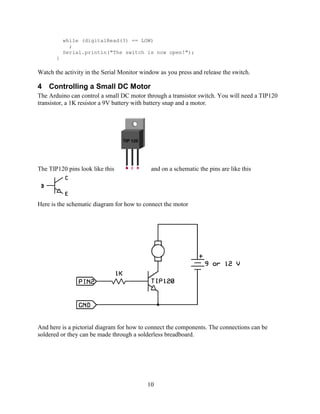
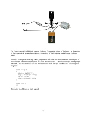
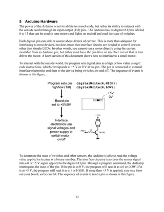
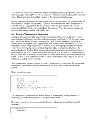
The document is an introduction guide to using Arduino microcontrollers. It describes that the Arduino is an open-source hardware platform used for building interactive objects and prototypes. The guide covers what is needed to set up an Arduino system, including the hardware components, software installation, and how to write basic programs to control an LED using the Arduino board.
The arduino uno is a microcontroller board based on thePramod Kumar
The document provides information about the Arduino Uno microcontroller board. It discusses the following key details:
- The Uno uses the ATmega328 microcontroller and has 14 digital input/output pins, 6 analog inputs, a USB connection, power jack, and reset button.
- It can be powered via USB or an external power source between 6-20V connected to the power jack or Vin pin.
- The board has 32KB of flash memory, 2KB of SRAM, and 1KB of EEPROM for storage. Communication is supported through serial via USB or pins 0 and 1, I2C, and SPI.
- The Uno can be programmed through the USB
The document provides information about how the Arduino board works. It explains that the Arduino uses an Atmega microcontroller chip which is programmed to control inputs and outputs. A secondary chip, such as an Atmega8U2, handles the USB connection and communication between the microcontroller and computer. Supporting components like voltage regulators, capacitors, crystals and resistors work together to power the chips safely and generate the clock signal needed for programming and operation.
Arduino is an open-source hardware and software platform for building interactive electronic projects. It consists of a programmable microcontroller board and IDE software to write code. The board contains ports that can be configured as digital or analog inputs/outputs to interact with sensors, LEDs, motors and other components. Common Arduino boards include the Uno, Nano, Mega and Leonardo, which differ in processor, memory and I/O pins. The ATmega328P microcontroller on the Uno uses a Harvard architecture with separate memory and buses for instructions and data, allowing simultaneous access.
The document introduces the Arduino microcontroller board. It describes the Arduino as an easy-to-use and inexpensive platform for physical computing. Key components of the Arduino include an ATmega328P microcontroller, digital and analog input/output pins, a USB connection for programming, and a standard pin layout that allows connection of expansion boards. The document provides an overview of the Arduino's capabilities and use in interactive projects.
This document provides an overview of an Arduino project. It describes what Arduino is, which is an open-source electronics platform that allows boards to read inputs and turn them into outputs. It then lists some of the key elements that are included in an Arduino board, such as a power supply connector, microcontroller, and reset button.
This document provides instructions for building music reactive multicolor LED lights that change color in response to the beat of music. The lights are made using an Arduino, RGB LED strip, audio input jack, and transistor circuit to amplify the Arduino signal. The 11 step instructions cover preparing an enclosure, soldering components, connecting the circuit to Arduino, adding an audio input, power, code upload, and using the finished project.
The document discusses circuits and components like resistors, capacitors, and transistors. It then describes integrated circuits, microcontrollers, and programmable circuit boards like Arduino. The Arduino uses a microcontroller and has input/output pins that can be programmed to control components like LEDs by writing code in C/C++ and uploading it to the board. Programming the Arduino allows users to build interactive electronic projects.
Arduino is an open-source hardware and software platform for building electronic projects and interactive objects. It consists of a circuit board with a microcontroller, and an IDE software to write and upload code. The boards can read inputs from sensors and turn them into outputs that control actuators. Arduino provides a standard format that simplifies use of microcontrollers. It allows controlling the board by sending instructions to the microcontroller via the Arduino IDE. The platform works with both the physical board and its libraries and IDE software.
The document provides information about the Arduino programming environment and hardware options. It discusses downloading the Arduino software, installing drivers, and an overview of the Arduino UNO board. It also lists several Arduino board options, shields that can expand functionality, components needed for projects like enclosures, power supplies, batteries, and various cables and breadboards.
This document provides information about the Arduino hardware platform. It defines Arduino as an open-source hardware platform used for prototyping that consists of a programmable circuit board and IDE software. It then describes the key features of Arduino boards, including reading analog/digital sensor inputs and controlling outputs. The document proceeds to explain the components of a basic Arduino board and how to install and use the Arduino IDE software to write and upload programs.
Arduino Uno is a microcontroller board based on 8-bit ATmega328P microcontroller. Along with ATmega328P, it consists other components such as crystal oscillator, serial communication, voltage regulator, etc. to support the microcontroller. Arduino Uno has 14 digital input/output pins (of which 6 can be used as PWM outputs), 6 analog inputs, a 16 MHz ceramic resonator, a USB connection, a power jack, an ICSP header, and a reset button.
This document summarizes an Arduino seminar report. It discusses what Arduino is, different Arduino boards, how the Arduino board works including the controller, power supply, and USB to serial converter. It also summarizes sensors that can interface with Arduino like temperature sensors and hall sensors. Finally, it provides an overview of a home automation project using Arduino and GSM to control devices remotely through SMS messages.
The Arduino Uno is a microcontroller board based on the ATmega328 with 14 digital input/output pins, 6 analog inputs, a USB connection, and a power jack. It contains everything needed to support the microcontroller and can be programmed using the Arduino IDE. The Uno differs from previous boards by using an Atmega8U2 as a USB-to-serial converter instead of an FTDI chip. It is the latest and reference version of the Arduino platform.
IRJET- Smart Gloves to Convert Sign Languages to Vocal OutputIRJET Journal
1) The document describes a smart glove that uses sensors and a microcontroller to convert sign language gestures into vocal outputs to help mute people communicate.
2) The glove contains flex sensors on the fingers to detect hand positions, a gyroscope to sense orientation, and a microcontroller connected to a speaker. Different finger positions produce different pre-recorded voice notes.
3) The sensors send data to the microcontroller which identifies the sign and plays the corresponding audio file through a connected speaker, translating signs into vocal speech in real-time. This system aims to help mute individuals communicate without needing an interpreter.
The document discusses Arduino, an open-source hardware platform used for building electronics projects. It notes that Arduino is a microcontroller board that can be programmed to read input and control output from various sensors and actuators. The document provides details on Arduino components, programming, common shields and expansions, applications in different domains, and its popularity as an accessible platform for physical computing.
Embedded system programming using Arduino microcontrollerArun Kumar
This document summarizes an technical seminar on embedded systems programming using Arduino. It introduces Arduino as an open-source electronic prototyping platform based on an I/O board and development environment. The document outlines Arduino's architecture including its microcontroller, power supply, and I/O pins. It also describes how to program Arduino using its IDE, setting up sketches with setup() and loop() functions, and provides examples of blinking an LED and serial communication. Finally, it discusses applications of Arduino such as home automation, robotics, and scientific equipment.
The document discusses the Arduino prototyping platform. It was started in Italy and uses an ATmega328P microcontroller with 28 pins and a maximum speed of 20 MHz. The Arduino can be powered through a USB or DC power jack and uses a 16 MHz crystal. It has digital and analog pins and can interface with PCs or mobile devices.
This document provides an overview of Arduino, an open-source hardware platform used for building interactive objects and prototypes. It describes Arduino as a single-board microcontroller intended to make electronics projects more accessible. Key topics covered include the Arduino programming environment, common Arduino boards and their features, examples of simple Arduino projects like blinking an LED and building a line-following robot, and comparisons to other prototyping platforms. The document encourages readers to get started with Arduino for its low cost, easy programming environment, and large community support.
An Arduino is an open-source electronics prototyping platform based around flexible, easy-to-use hardware and software. It contains a microchip which can be programmed to sense inputs from sensors or buttons and control outputs like LEDs or motors. It is used to create interactive objects or environments. The Arduino software runs on Windows, Mac, and Linux and is used to write programs, or "sketches", that are then uploaded to the Arduino board. Basic circuits and programming concepts are explained through examples of blinking an LED and controlling it with a potentiometer or switch.
The Arduino Uno Board is an open resource microcontroller board based on the ATmega328 chip. This Board has 14 digital I/O pins, 6 analog input pins, onboard 16 MHz ceramic resonator, Port for USB connection, Onboard DC power jack, An ICSP header and a microcontroller reset button. Robomart is the biggest selling store in india buy arduino board, buy arduino online, arduino india, arduino uno price, arduino uno india, arduino uno price in india, arduino board price in india at best prices. https://www.robomart.com/arduino-uno-online-india
Arduino for beginners- Introduction to Arduino (presentation) - codewithgauriGaurav Pandey
The document provides an overview of the Arduino platform for beginners. It defines Arduino as an open-source platform used for building electronics projects. All Arduino boards contain a microcontroller, which is a small computer. It then describes some popular Arduino boards like the Uno, Nano, Due, and Mega and their key specs and applications. The document proceeds to explain the main components of an Arduino Uno board such as the power supply, USB port, microcontroller, analog and digital pins. It provides details on the functions of these components and how they enable the Arduino board to operate.
This document provides an overview of the Arduino open source electronics prototyping platform. It describes the history and origins of Arduino starting in 2005 at the Interactive Design Institute in Italy. Key Arduino boards are identified like the Arduino Uno, the most popular board. The features of the Arduino Uno board are outlined including its microcontroller, pins for input/output, power supply and more. The Arduino IDE software for writing and uploading code to Arduino boards is also summarized. Other open source prototyping platforms besides Arduino are mentioned but not described.
The document discusses Arduino, an open-source electronics prototyping platform. It began in 2005 as a cheaper alternative for students to use in physical computing classes compared to other microcontroller boards. Arduino boards use a microcontroller, such as the Atmega328, and can be programmed and controlled from a computer. The Arduino software and hardware designs are open-source, allowing anyone to build upon and distribute Arduino clones and compatible boards. The Arduino platform and community have grown significantly since 2005.
This presentation summarizes a summer training on Arduino. It defines Arduino as an open-source hardware and software platform for building electronics projects. It describes the main types of Arduino boards including the Arduino Uno, Mega 2560, Duemilanove, and Fio. It also outlines some key features of the Arduino Uno board. Furthermore, it provides examples of interfacing Arduino with a DC motor and RC car motor. The presentation concludes by listing some common applications of Arduino and its advantages.
The document provides information about interfacing an RF transmitter module with an Arduino board. It includes the technical specifications of the RF transmitter and receiver modules. The circuit diagram shows how to connect the RF transmitter module to an Arduino board. It also includes the Arduino code for the RF transmitter to send digital signals and the RF receiver code to receive the signals and control an LED accordingly.
The document provides an introduction to programming with Arduino. It explains that Arduino is an open-source hardware and software platform used to build interactive electronic projects. It consists of a microcontroller board that can be programmed and used to read and control sensors, LEDs, motors and more. The document outlines the basic steps to get started which include downloading the Arduino IDE, installing drivers, selecting the board type, and uploading a test "Blink" program to make an LED turn on and off. It also provides explanations of some core electronic components like resistors, LEDs, sensors and describes how to set up a simple temperature sensing project and store the sensor readings in a database.
The document provides an overview of the Arduino platform, including what it is, what it is used for, and how to get started using it. Key points:
- Arduino is an open-source hardware and software platform for building interactive electronic projects through a simple programming language.
- It is used for physical computing projects, interactive installations, and rapid prototyping. Projects can include sensors and actuators.
- Getting started requires an Arduino board, USB cable, power supply, and downloading the IDE (integrated development environment) to write and upload code. Basic electrical safety knowledge is also important.
The document presents an overview of Arduino. It defines Arduino as an open-source physical computing platform using a simple input/output board and Processing/Wiring language development environment. It describes common Arduino boards like Uno, Mega 2560, and Duemilanove. Features of the Arduino Uno are outlined, including basic terminology in Arduino like analog to digital conversion and pulse width modulation. Examples of interfacing Arduino with DC motors and RC car motors are provided. The document concludes with advantages of Arduino like low cost and cross-platform IDE.
TECH TALK-4TH SEM.pptx.which is about the arduino uno types and uses.gokulprasanna4
The document presents an overview of Arduino. It defines Arduino as an open-source physical computing platform using a simple input/output board and Processing/Wiring language development environment. It describes common Arduino boards like Uno, Mega 2560, and Duemilanove. Features of the Arduino Uno are outlined, including analog/digital pins and memory specifications. Basic Arduino terminology is defined, such as analog-to-digital conversion and pulse width modulation. Examples of interfacing Arduino with DC motors and RC car motors are provided. The document concludes with advantages of Arduino like low cost and cross-platform IDE.
The document provides an overview of the Arduino prototyping platform. It discusses the main components of Arduino including the Arduino board itself, external hardware like sensors and actuators, and the Arduino IDE. It describes the key capabilities of Arduino boards like the ATmel microcontroller, I/O pins, and programming interfaces. The Arduino can be used to build all kinds of projects from automatic plant watering systems to quadcopter autopilots by connecting various external hardware and programming it using the Arduino IDE.
The document provides an introduction to Arduino boards. It describes that Arduinos contain a microcontroller and can be programmed to interact with electronic components. The specific board being discussed, the Arduino Uno R3, contains an ATmega328 chip, has ports for digital and analog input/output, and can be expanded with shields. The document also outlines how to install the Arduino IDE software and provides an example code to fade an LED on and off.
Chapter 5 Arduino Microcontroller Systems .pptxkhgh7
This document provides an overview of Arduino microcontroller systems. It defines Arduino as an open-source prototyping platform used to develop devices that can read inputs and provide outputs. Key components of the Arduino board are described, including the microcontroller, USB port, pins for digital and analog input/output. Basic concepts like circuits, sensors, actuators, serial communication protocols, memory and the embedded Arduino UNO board are explained at a high level. References for further reading are also provided.
This document provides an overview and introduction to a digital home automation project using Arduino and Bluetooth. The project aims to develop a home automation system that allows appliances to be remotely controlled via an Android smartphone application. Key components include an Arduino Uno microcontroller, HC-05 Bluetooth module, relays, and an Android app. The system allows electrical appliances like lights and fans to be switched on or off from a smartphone. The Arduino code controls the relays based on commands received over Bluetooth from the Android app.
ARDUINO OVERVIEW HARDWARE SOFTWARE AND INSTALLATION.pdfRuby Hermano
This document provides an overview of the Arduino hardware and software platform. It discusses that Arduino is an open-source electronics platform that can read inputs and turn them into outputs. Common Arduino boards like the UNO, Nano, Leonardo and Micro are identified along with their key components and specifications. The document also explains the benefits of using Arduino including its low cost, cross-platform software, simple programming and extensible open-source hardware and software.
This document provides an introduction to the Arduino, an open-source electronics prototyping platform. It explains that Arduino uses a microchip that can be programmed to sense inputs from sensors and control outputs to other devices. It also covers basic electronics concepts like digital and analog inputs/outputs, and shows how to set up a simple circuit with an LED and use code to blink the LED.
This document provides an introduction to the Arduino electronics prototyping platform. It explains that Arduino is an open-source platform used to build interactive electronic projects through hardware and software. The document covers basic concepts such as inputs and outputs, digital and analog signals, circuits, and programming Arduino with a simple blink example. It also demonstrates attaching basic components like LEDs, buttons, and potentiometers to control outputs and read inputs.
Arduino is an open-source platform that allows users to create interactive electronics projects. It consists of a microcontroller board, which is essentially a small computer, and various input and output pins that can be programmed using the Arduino Integrated Development Environment (IDE). The platform is relatively inexpensive and easy to use, making it popular among hobbyists, students, and professionals alike.
The Arduino board is the heart of the platform, and it comes in different variations that cater to different projects. At the center of the board is a microcontroller, which is essentially a small computer that controls the inputs and outputs of the board.
In addition to the microcontroller, the board also has various input and output pins that can be used to connect different sensors and actuators to the board. These pins allow the board to interact with the outside world and perform different functions depending on the project.
Visit https://robomart.com/ for more info
The document describes an Arduino-based home automation system that can sense various parameters like temperature, distance, light, and detect burglars. It transmits the sensor data to an Arduino board which processes the data and checks it against the program code to control devices like fans accordingly. The system also allows users to set alerts. It then provides details about Arduino programming, including the languages, code structure, and functions used. It gives an example of a circuit and code to light LEDs and explains various Arduino functions like pinMode(), digitalWrite(), analogRead() etc.
Buy Arduino UNO R3 Boards are available on robomart at cheap price in India.Robomart is the biggest online shopping place .the link is given below https://www.robomart.com/arduino-uno-online-india
ARDUINO OVERVIEW HARDWARE SOFTWARE AND INSTALLATION.pptxmenchc1207
The document provides an overview of the Arduino hardware and software platform. It discusses that Arduino is an open-source electronics platform that can read inputs and turn them into outputs. Some common Arduino boards are then described, including the Arduino UNO, Nano, Leonardo, and Micro. The Arduino UNO is highlighted as one of the most popular boards due to its extensive documentation and tutorials available. The key components of the Arduino UNO board are then outlined.
The document proposes a solution to automate electricity meter reading in Pakistan using Arduino technology. An Arduino chip would be installed inside each electricity meter and connected to a 4G shield. The Arduino would record consumption data and transmit it via the 4G shield to a WAPDA server. This would allow remote meter reading and billing, reducing costs compared to the current manual process.
This document provides information about the Arduino platform and its common characteristics for IoT applications. It describes the Arduino board, including its pin layout and functions. It then summarizes several Arduino board variants, including the Uno, Lilypad, Red Board, Mega, and Leonardo. The Uno has 14 digital pins with 6 PWM outputs and 6 analog inputs. The Lilypad is designed for wearables and e-textiles. The Red Board is flat for embedding. The Mega has more pins for more complex projects. The Leonardo has a microcontroller with built-in USB functionality.
The document discusses the Arduino Nano development board. It provides an overview of the board's specifications including its microcontroller, operating voltage, analog and digital pins, memory, and communication interfaces. It also compares the Nano to the Arduino Uno and Arduino Mega boards, highlighting their differences in size, programming, and technical specifications. The document then provides instructions on how to power and program the Nano board using the Arduino IDE and examples.
Controlling home appliances using remoteRajan Gautam
This document describes a circuit designed to control home or industrial appliances using a remote control. The circuit uses a step-down transformer, voltage regulator, change-over relay, timer IC, and IR receiver module. When a button on the remote is pressed, the IR receiver detects the signal and triggers the timer IC, energizing the relay and switching the appliance on or off. The circuit allows controlling appliances from up to 10 meters away, reducing effort and saving time compared to manual operation.
The document discusses I/O ports on the ATMEGA16 microcontroller. It provides background information on I/O port registers including PORTx, DDRx, and PINx. It then outlines six projects related to I/O ports - two involving interfacing LEDs, two involving interfacing switches, one involving a digital clock, and one involving serial communication. Schematics, board layouts, sample code and explanations are provided for each project.
The document provides an overview of the ATmega16 microcontroller and how to program it using AVR Studio and burn the code using AVR osp-2 or Sina Prog 2.1. It discusses the ports and pins of the ATmega16, writing code in AVR Studio, configuring AVR osp-2 to burn the code, and interfacing examples like LED blinking, LCD, ADC, and serial communication.
The document summarizes the features and specifications of the Atmel ATmega328/P 8-bit microcontroller. It includes 32KB of flash memory, 2KB of SRAM, 1KB of EEPROM, 23 general purpose I/O lines, two 8-bit timers/counters, one 16-bit timer/counter, an 8-channel 10-bit ADC, SPI, I2C, and USART interfaces, and sleep modes for low power operation. It operates at speeds between 0-20MHz and supports in-system programming and self-programming of the flash memory through boot code. The microcontroller is available in PDIP, TQFP, and QFN packages and is supported by development tools
The document describes an Atmel microcontroller with features such as a powerful instruction set, 32 general purpose registers, various memory segments including flash, EEPROM and SRAM, in-system programming, analog and digital peripherals, and low power consumption. It includes pinout diagrams and descriptions of the microcontroller's I/O ports, voltage supplies, and packages. Key specifications listed are operating voltage, temperature range, speed grades, and power consumption levels.
This document provides an introduction to programming an Atmega microcontroller. It discusses the compilation and transfer process, including installing necessary tools. It then covers basic concepts like pins, ports, and bit manipulation. The document uses tutorials to demonstrate controlling an LED and reading inputs. It also introduces timers, ADC, UART serial communication, and peripherals like servos. An appendix provides reference information on bit operations and the pinout of an Atmega 168 microcontroller.
The document discusses trees as a non-linear data structure used to represent hierarchical relationships. It defines key tree terminology like root, node, degree, siblings, and levels. It also covers different types of trees like binary trees and their properties. Binary trees are represented using arrays, with the root at index 0 and children at successive indices. The document provides formulas to identify a node's parent and children from its array index.
Static memory allocation assigns memory at compile time using arrays, while dynamic allocation assigns memory at runtime using pointers. Dynamic allocation overcomes issues with static allocation like wasted memory and unknown memory needs. The malloc() function dynamically allocates memory, returning a void pointer. The free() function deallocates memory to avoid memory leaks. Linked lists use dynamic allocation through malloc() and free() to overcome array limitations like unknown sizes and complex insertions/deletions. Linked lists have nodes with data and next pointer, allowing flexible memory usage through various operations like creation, insertion, deletion, traversal and searching.
Queue is a linear data structure where elements are inserted at the rear end and deleted from the front end, following FIFO (First In First Out) principle. A queue can be implemented using arrays or linked lists. The document discusses implementation of queues using static arrays and dynamic memory allocation. It also covers insertion and deletion algorithms and provides examples of queue operations using both array-based and linked list-based implementations. Circular queues are introduced as an enhancement over standard queues to avoid overflow in static array implementation.
1. The document discusses stacks and their implementation as a data structure. Stacks follow the last-in, first-out (LIFO) principle and can be implemented using either arrays (static implementation) or linked lists (dynamic implementation).
2. Common stack operations like push, pop, peek and isEmpty are described along with their time complexities. Converting expressions from infix to postfix notation using stacks is also covered.
3. Examples of implementing stacks using arrays and linked lists in C programming language are provided, including functions for push, pop and traversal operations. Converting infix expressions to equivalent postfix forms using stack operations is demonstrated through examples.
Structures allow the grouping of different data types together under one name. They are useful for storing records with multiple related data fields, like a student record with a name, roll number, and marks. Structures can be initialized, passed to functions by value or reference, and used to create arrays of records. Unions share the same memory location for different member types, while structures allocate separate memory for each member.
This document discusses arrays in C programming. It defines an array as a collection of variables of the same type that are referenced by a common name. It describes single-dimensional and multi-dimensional arrays. Single-dimensional arrays are comprised of finite, homogeneous elements while multi-dimensional arrays have elements that are themselves arrays. The document provides examples of declaring, initializing, accessing, and implementing arrays in memory for both single and double-dimensional arrays. It includes sample programs demonstrating various array operations.
Harnessing WebAssembly for Real-time Stateless Streaming PipelinesChristina Lin
Traditionally, dealing with real-time data pipelines has involved significant overhead, even for straightforward tasks like data transformation or masking. However, in this talk, we’ll venture into the dynamic realm of WebAssembly (WASM) and discover how it can revolutionize the creation of stateless streaming pipelines within a Kafka (Redpanda) broker. These pipelines are adept at managing low-latency, high-data-volume scenarios.
Understanding Inductive Bias in Machine LearningSUTEJAS
This presentation explores the concept of inductive bias in machine learning. It explains how algorithms come with built-in assumptions and preferences that guide the learning process. You'll learn about the different types of inductive bias and how they can impact the performance and generalizability of machine learning models.
The presentation also covers the positive and negative aspects of inductive bias, along with strategies for mitigating potential drawbacks. We'll explore examples of how bias manifests in algorithms like neural networks and decision trees.
By understanding inductive bias, you can gain valuable insights into how machine learning models work and make informed decisions when building and deploying them.
Using recycled concrete aggregates (RCA) for pavements is crucial to achieving sustainability. Implementing RCA for new pavement can minimize carbon footprint, conserve natural resources, reduce harmful emissions, and lower life cycle costs. Compared to natural aggregate (NA), RCA pavement has fewer comprehensive studies and sustainability assessments.
Advanced control scheme of doubly fed induction generator for wind turbine us...IJECEIAES
This paper describes a speed control device for generating electrical energy on an electricity network based on the doubly fed induction generator (DFIG) used for wind power conversion systems. At first, a double-fed induction generator model was constructed. A control law is formulated to govern the flow of energy between the stator of a DFIG and the energy network using three types of controllers: proportional integral (PI), sliding mode controller (SMC) and second order sliding mode controller (SOSMC). Their different results in terms of power reference tracking, reaction to unexpected speed fluctuations, sensitivity to perturbations, and resilience against machine parameter alterations are compared. MATLAB/Simulink was used to conduct the simulations for the preceding study. Multiple simulations have shown very satisfying results, and the investigations demonstrate the efficacy and power-enhancing capabilities of the suggested control system.
Optimizing Gradle Builds - Gradle DPE Tour Berlin 2024Sinan KOZAK
Sinan from the Delivery Hero mobile infrastructure engineering team shares a deep dive into performance acceleration with Gradle build cache optimizations. Sinan shares their journey into solving complex build-cache problems that affect Gradle builds. By understanding the challenges and solutions found in our journey, we aim to demonstrate the possibilities for faster builds. The case study reveals how overlapping outputs and cache misconfigurations led to significant increases in build times, especially as the project scaled up with numerous modules using Paparazzi tests. The journey from diagnosing to defeating cache issues offers invaluable lessons on maintaining cache integrity without sacrificing functionality.
ACEP Magazine edition 4th launched on 05.06.2024Rahul
This document provides information about the third edition of the magazine "Sthapatya" published by the Association of Civil Engineers (Practicing) Aurangabad. It includes messages from current and past presidents of ACEP, memories and photos from past ACEP events, information on life time achievement awards given by ACEP, and a technical article on concrete maintenance, repairs and strengthening. The document highlights activities of ACEP and provides a technical educational article for members.
DEEP LEARNING FOR SMART GRID INTRUSION DETECTION: A HYBRID CNN-LSTM-BASED MODELgerogepatton
As digital technology becomes more deeply embedded in power systems, protecting the communication
networks of Smart Grids (SG) has emerged as a critical concern. Distributed Network Protocol 3 (DNP3)
represents a multi-tiered application layer protocol extensively utilized in Supervisory Control and Data
Acquisition (SCADA)-based smart grids to facilitate real-time data gathering and control functionalities.
Robust Intrusion Detection Systems (IDS) are necessary for early threat detection and mitigation because
of the interconnection of these networks, which makes them vulnerable to a variety of cyberattacks. To
solve this issue, this paper develops a hybrid Deep Learning (DL) model specifically designed for intrusion
detection in smart grids. The proposed approach is a combination of the Convolutional Neural Network
(CNN) and the Long-Short-Term Memory algorithms (LSTM). We employed a recent intrusion detection
dataset (DNP3), which focuses on unauthorized commands and Denial of Service (DoS) cyberattacks, to
train and test our model. The results of our experiments show that our CNN-LSTM method is much better
at finding smart grid intrusions than other deep learning algorithms used for classification. In addition,
our proposed approach improves accuracy, precision, recall, and F1 score, achieving a high detection
accuracy rate of 99.50%.
KuberTENes Birthday Bash Guadalajara - K8sGPT first impressionsVictor Morales
K8sGPT is a tool that analyzes and diagnoses Kubernetes clusters. This presentation was used to share the requirements and dependencies to deploy K8sGPT in a local environment.
1. 1
Arduino Microcontroller Guide
W. Durfee, University of Minnesota ver. oct-2011
Available on-line at www.me.umn.edu/courses/me2011/arduino/
1 Introduction
1.1 Overview
The Arduino microcontroller is an easy to use yet powerful single board computer that has
gained considerable traction in the hobby and professional market. The Arduino is open-source,
which means hardware is reasonably priced and development software is free. This guide is for
students in ME 2011, or students anywhere who are confronting the Arduino for the first time.
For advanced Arduino users, prowl the web; there are lots of resources.
The Arduino project was started in Italy to develop low cost hardware for interaction design. An
overview is on the Wikipedia entry for Arduino. The Arduino home page is
http://www.arduino.cc/.
The Arduino hardware comes in several flavors. In the United States, Sparkfun
(www.sparkfun.com) is a good source for Arduino hardware.
This guide covers the Arduino Uno board (Sparkfun DEV-09950, $29.95), a good choice for
students and educators. With the Arduino board, you can write programs and create interface
circuits to read switches and other sensors, and to control motors and lights with very little effort.
Many of the pictures and drawings in this guide were taken from the documentation on the
Arduino site, the place to turn if you need more information. The Arduino section on the ME
2011 web site, https://sites.google.com/a/umn.edu/me2011/, covers more on interfacing the
Arduino to the real world.
This is what the Arduino board looks like.
2. 2
The Duemilanove board features an Atmel ATmega328 microcontroller operating at 5 V with 2
Kb of RAM, 32 Kb of flash memory for storing programs and 1 Kb of EEPROM for storing
parameters. The clock speed is 16 MHz, which translates to about executing about 300,000 lines
of C source code per second. The board has 14 digital I/O pins and 6 analog input pins. There is
a USB connector for talking to the host computer and a DC power jack for connecting an
external 6-20 V power source, for example a 9 V battery, when running a program while not
connected to the host computer. Headers are provided for interfacing to the I/O pins using 22 g
solid wire or header connectors. For additional information on the hardware, see
http://arduino.cc/en/Main/ArduinoBoardUno.
The Arduino programming language is a simplified version of C/C++. If you know C,
programming the Arduino will be familiar. If you do not know C, no need to worry as only a few
commands are needed to perform useful functions.
An important feature of the Arduino is that you can create a control program on the host PC,
download it to the Arduino and it will run automatically. Remove the USB cable connection to
the PC, and the program will still run from the top each time you push the reset button. Remove
the battery and put the Arduino board in a closet for six months. When you reconnect the battery,
the last program you stored will run. This means that you connect the board to the host PC to
develop and debug your program, but once that is done, you no longer need the PC to run the
program.
1.2 What You Need for a Working System
1. Arduino Duemilanove board
2. USB programming cable (A to B)
3. 9V battery or external power supply (for stand-alone operation)
4. Solderless breadboard for external circuits, and 22 g solid wire for connections
5. Host PC running the Arduino development environment. Versions exist for Windows, Mac
and Linux
1.3 Installing the Software
Follow the instructions on the Getting Started section of the Arduino web site,
http://arduino.cc/en/Guide/HomePage. Go all the way through the steps to where you see the pin
13 LED blinking. This is the indication that you have all software and drivers successfully
installed and can start exploring with your own programs.
1.4 Connecting a Battery
For stand-alone operation, the board is powered by a battery rather than through the USB
connection to the computer. While the external power can be anywhere in the range of 6 to 24 V
(for example, you could use a car battery), a standard 9 V battery is convenient. While you could
jam the leads of a battery snap into the Vin and Gnd connections on the board, it is better to
solder the battery snap leads to a DC power plug and connect to the power jack on the board. A
suitable plug is part number 28760 from www.jameco.com. Here is what this looks like.
3. 3
Warning: Watch the polarity as you connect your battery to the snap as reverse orientation
could blow out your board.
Disconnect your Arduino from the computer. Connect a 9 V battery to the Arduino power jack
using the battery snap adapter. Confirm that the blinking program runs. This shows that you can
power the Arduino from a battery and that the program you download runs without needing a
connection to the host PC
1.5 Moving On
Connect your Arduino to the computer with the USB cable. You do not need the battery for now.
The green PWR LED will light. If there was already a program burned into the Arduino, it will
run.
Warning: Do not put your board down on a conductive surface; you will short out the pins on
the back!
Start the Arduino development environment. In Arduino-speak, programs are called “sketches”,
but here we will just call them programs.
In the editing window that comes up, enter the following program, paying attention to where
semi-colons appear at the end of command lines.
void setup()
{
Serial.begin(9600);
Serial.println("Hello World");
}
void loop()
{}
Your window will look something like this
4. 4
Click the Upload button or Ctrl-U to compile the program and load on the Arduino board.
Click the Serial Monitor button . If all has gone well, the monitor window will show your
message and look something like this
Congratulations; you have created and run your first Arduino program!
5. 5
Push the Arduino reset button a few times and see what happens.
Hint: If you want to check code syntax without an Arduino board connected, click the Verify
button or Ctrl-R.
Hint: If you want to see how much memory your program takes up, Verify then look at the
message at the bottom of the programming window.
1.6 Troubleshooting
If there is a syntax error in the program caused by a mistake in typing, an error message will
appear in the bottom of the program window. Generally, staring at the error will reveal the
problem. If you continue to have problems, try these ideas
Run the Arduino program again
Check that the USB cable is secure at both ends.
Reboot your PC because sometimes the serial port can lock up
If a “Serial port…already in use” error appears when uploading
Ask a friend for help
1.7 Solderless Breadboards
A solderless breadboard is an essential tool for rapidly prototyping electronic circuits.
Components and wire push into breadboard holes. Rows and columns of holes are internally
connected to make connections easy. Wires run from the breadboard to the I/O pins on the
Arduino board. Make connections using short lengths of 22 g solid wire stripped of insulation
about 0.25” at each end. Here is a photo of a breadboard showing which runs are connected
internally. The pairs of horizontal runs at the top and bottom are useful for running power and
ground. Convention is to make the red colored run +5 V and the blue colored run Gnd. The
power runs are sometimes called “power busses”.
6. 6
Warning: Only use solid wire on the breadboard. Strands of stranded wire can break off and fill
the holes permanently.
Hint: Trim wires and component leads so that wires and components lie close to the board.
To keep the Arduino board and breadboard together, you can secure both to a piece of fom-core,
cardboard or wood using double-stick foam tape or other means.
2 Flashing an LED
Light emitting diodes (LED's) are handy for checking out what the Arduino can do.. For this
task, you need an LED, a 330 ohm resistor, and some short
pieces of 22 or 24 g wire. The figure to the right is a sketch
of an LED and its symbol used in electronic schematics
Using 22 g solid wire, connect the 5V power pin on the
Arduino to the bottom red power bus on the breadboard and
the Gnd pin on the Arduino to the bottom blue power buss
on the breadboard. Connect the notched or flat side of the LED (the notch or flat is on the rim
that surrounds the LED base; look carefully because it can be hard to find) to the Gnd bus and
the other side to a free hole in main area of the breadboard Place the resistor so that one end is in
the same column as the LED and the other end is in a free column. From that column, connect a
wire to digital pin 2 on the Arduino board. Your setup will look something like this
Horizontal runs connected
Vertical runs
connected
Horizontal runs connected
Vertical runs
connected
7. 7
To test whether the LED works, temporarily
disconnect the wire from pin 2 on the Arduino
board and touch to the 5V power bus. The LED
should light up. If not, try changing the orientation
of the LED. Place the wire back in pin 2.
On the LED, current runs from the anode (+) to the
cathode (-) which is marked by the notch. The
circuit you just wired up is represented in schematic
form in the figure to the right.
Create and run this Arduino program
void setup()
{
pinMode(2,OUTPUT);
digitalWrite(2,HIGH);
delay(1000);
digitalWrite(2,LOW);
}
void loop()
{}
Did the LED light up for one second? Push the Arduino reset button to run the program again.
Now try this program, which will flash the LED at 1.0 Hz. Everything after the // on a line is a
comment, as is the text between „/*‟ and „*/‟ at the top. It is always good to add comments to a
program.
/*---------------------------
Blinking LED, 1.0 Hz on pin 2
----------------------------*/
PIN 2
Gnd
330
8. 8
void setup() // one-time actions
{
pinMode(2,OUTPUT); // define pin 2 as an output
}
void loop() // loop forever
{
digitalWrite(2,HIGH); // pin 2 high (LED on)
delay(500); // wait 500 ms
digitalWrite(2,LOW); // pin 2 low (LED off)
delay(500); // wait 500 ms
}
The pinMode command sets the LED pin to be an output. The first digitalWrite command says to
set pin 2 of the Arduino to HIGH, or +5 volts. This sends current from the pin, through the
resistor, through the LED (which lights it) and to ground. The delay(500) command waits for
500 msec. The second digitalWrite command sets pin 2 to LOW or 0 V stopping the current
thereby turning the LED off. Code within the brackets defining the loop() function is repeated
forever, which is why the LED blinks.
This exercise shows how the Arduino can control the outside world. With proper interface
circuitry the same code can turn on and off motors, relays, solenoids, electromagnets, pneumatic
valves or any other on-off type device.
3 Reading a switch
The LED exercise shows how the Arduino can control
the outside world. Many applications require reading the
state of sensors, including switches. The figure to the
right shows a picture of a pushbutton switch and its
schematic symbol. Note that the symbol represents a
switch whose contacts are normally open, but then are
shorted when the button is pushed. If you have a switch,
use the continuity (beeper) function of a digital multi-
meter (DMM) to understand when the leads are open and
when they are connected as the button is pushed.
For this exercise, the Arduino will read the state of a normally-open push button switch and
display the results on the PC using the serial.println() command. You will need a switch, a 10
kohm resistor and some pieces of 22 g hookup wire. If you don't have a switch, substitute two
wires and manually connect their free ends to simulate a switch closure. The figure below shows
the schematic for the circuit on the left and a realization on the right.
9. 9
Create and run this Arduino program
void setup()
{
Serial.begin(9600);
}
void loop()
{
Serial.println(digitalRead(3));
delay(250);
}
Open the Serial Monitor window. When the switch is open, you should see a train of 1's on the
screen. When closed, the 1's change to 0's. On the hardware side, when the switch is open, no
current flows through the resistor. When no current flows through a resistor, there is no voltage
drop across the resistor, which means the voltage on each side is the same. In your circuit, when
the switch is open, pin 3 is at 5 volts which the computer reads as a 1 state. When the switch is
closed, pin 3 is directly connected to ground, which is at 0 volts. The computer reads this as a 0
state.
Now try this program which is an example of how you can have the computer sit and wait for a
sensor to change state.
void setup()
{
Serial.begin(9600);
}
void loop()
{
while (digitalRead(3) == HIGH)
;
Serial.println("Somebody closed the switch!");
10K
PIN 3
+5 V
Gnd
10K
PIN 3
+5 V
Gnd
10. 10
while (digitalRead(3) == LOW)
;
Serial.println("The switch is now open!");
}
Watch the activity in the Serial Monitor window as you press and release the switch.
4 Controlling a Small DC Motor
The Arduino can control a small DC motor through a transistor switch. You will need a TIP120
transistor, a 1K resistor a 9V battery with battery snap and a motor.
The TIP120 pins look like this and on a schematic the pins are like this
Here is the schematic diagram for how to connect the motor
And here is a pictorial diagram for how to connect the components. The connections can be
soldered or they can be made through a solderless breadboard.
11. 11
Pin 2 can be any digital I/O pin on your Arduino. Connect the minus of the battery to the emitter
of the transistor (E pin) and also connect the emitter of the transistor to Gnd on the Arduino
board.
To check if things are working, take a jumper wire and short the collector to the emitter pins of
the transistor. The motor should turn on. Next, disconnect the 1K resistor from pin 2 and jumper
it to +5V. The motor should turn on. Put the resistor back into pin 2 and run the following test
program:
void setup()
{
pinMode(2,OUTPUT);
digitalWrite(2,HIGH);
delay(1000);
digitalWrite(2,LOW);
}
void loop()
{}
The motor should turn on for 1 second.
Pin 2
Gnd
Pin 2Pin 2
Gnd
Pin 2
12. 12
5 Arduino Hardware
The power of the Arduino is not its ability to crunch code, but rather its ability to interact with
the outside world through its input-output (I/O) pins. The Arduino has 14 digital I/O pins labeled
0 to 13 that can be used to turn motors and lights on and off and read the state of switches.
Each digital pin can sink or source about 40 mA of current. This is more than adequate for
interfacing to most devices, but does mean that interface circuits are needed to control devices
other than simple LED's. In other words, you cannot run a motor directly using the current
available from an Arduino pin, but rather must have the pin drive an interface circuit that in turn
drives the motor. A later section of this document shows how to interface to a small motor.
To interact with the outside world, the program sets digital pins to a high or low value using C
code instructions, which corresponds to +5 V or 0 V at the pin. The pin is connected to external
interface electronics and then to the device being switched on and off. The sequence of events is
shown in this figure.
To determine the state of switches and other sensors, the Arduino is able to read the voltage
value applied to its pins as a binary number. The interface circuitry translates the sensor signal
into a 0 or +5 V signal applied to the digital I/O pin. Through a program command, the Ardiomp
interrogates the state of the pin. If the pin is at 0 V, the program will read it as a 0 or LOW. If it
is at +5 V, the program will read it as a 1 or HIGH. If more than +5 V is applied, you may blow
out your board, so be careful. The sequence of events to read a pin is shown in this figure.
Program sets pin
high/low (1/0)
Board pin
set to +5V/0V
Interface
electronics use
signal voltages and
power supply to
switch motor
on/off
digitalWrite(4,HIGH);
digitalWrite(4,LOW);
+5V
0V
TIP120
1KPIN 4
+12 V
Program sets pin
high/low (1/0)
Board pin
set to +5V/0V
Interface
electronics use
signal voltages and
power supply to
switch motor
on/off
digitalWrite(4,HIGH);
digitalWrite(4,LOW);
+5V
0V
TIP120
1KPIN 4
+12 V
13. 13
Interacting with the world has two sides. First, the designer must create electronic interface
circuits that allow motors and other devices to be controlled by a low (1-10 mA) current signal
that switches between 0 and 5 V, and other circuits that convert sensor readings into a switched 0
or 5 V signal. Second, the designer must write a program using the set of Arduino commands
that set and read the I/O pins. Examples of both can be found in the Arduino resources section of
the ME2011 web site.
When reading inputs, pins must have either 0 or 5V applied. If a pin is left open or "floating", it will read random
voltages and cause erratic results. This is why switches always have a 10K pull up resistor connected when
interfacing to an Arduino pin.
Note: The reason to avoid using pins 0 and 1 is because those pins are used for the serial communications between
the Arduino and the host computer.
The Arduino also has six analog input pins for reading continuous voltages in the range of 0 to 5
V from sensors such as potentiometers.
6 Programming Concepts
This chapter covers some basic concepts of computer programming, going under the assumption
that the reader is a complete novice.
A computer program is a sequence of step-by-step instructions for the computer to follow. The
computer will do exactly what you tell it to do, no more no less. The computer only knows
what's in the program, not what you intended. Thus the origin of the phrase, "Garbage in,
garbage out".
Program reads
value of pins (1/0)
Board pins
set to +5V/0V
Interface
electronics change
sensor signals into
+5V/0V
digitalRead(4);
10K
PIN 4
+5 V
+5V
0V
Program reads
value of pins (1/0)
Board pins
set to +5V/0V
Interface
electronics change
sensor signals into
+5V/0V
digitalRead(4);
10K
PIN 4
+5 V
+5V
0V
+5V
0V
14. 14
The set of valid instructions comes from the particular programming language used. There are
many languages, including C, C++, Java, Ada, Lisp, Fortran, Basic, Pascal, Perl, and a thousand
others. The Arduino uses a simplified variation of the C programming language.
For any programming language, the instructions must be entered in a specific syntax in order for
the computer to interpret them properly. Typically, the interpretation is a two step process. A
compiler takes the language specific text you enter for the program and converts it into a
machine readable form that is downloaded into the processor. When the program executes, the
processor executes the machine code line by line.
6.1 Basics of Programming Languages
All sequential programming languages have four categories of instructions. First are operation
commands that evaluate an expression, perform arithmetic, toggle states of I/O lines, and many
other operations. Second are jump commands that cause the program to jump immediately to
another part of the program that is tagged with a label. Jumps are one way to break out of the
normal line-by-line processing mode. For example, if you want a program to repeat over and
over without stopping, have the last line of the program be a jump command that takes the
program back to its first line. Third are branch commands that evaluate a condition and jump if
the condition is true. For example, you might want to jump only if a number is greater than zero.
Or, you might want to jump only if the state of an i/o line is low. Fourth are loop commands that
repeat a section of code a specified number of times. For example, with a loop you can have a
light flash on and off exactly six times.
Most programming languages contain a relatively small number of commands. The complexity
of computers comes from combining and repeating the instructions several million times a
second.
Here's a generic program.
1. Do this
2. Do that
3. Jump to instruction 6
4. Do the other thing
5. All done, sleep
6. If switch closed, do that thing you do
7. Jump to instruction 4
The computer will execute this line by line. The art of programming is simply a matter of
translating your intent into a sequence of instructions that match.
Here is an example of a for loop command followed by a branch command that uses an IF
statement
for (i=0;i<6,i++) {
instructions
}
15. 15
if (j > 4) goto label
instructions
The commands inside the loop will be repeated six times. Following this, if the value of the
variable j is greater than 4, the program will skip to the instruction tagged with the specified
label, and if not, the line following the if statement will be executed.
In addition to the basic commands, languages have the ability to call functions which are
independent sections of code that perform a specific task. Functions are a way of calling a
section of code from a number of different places in the program and then returning from that
section to the line that follows the calling line. Here's an example
apples();
instructions
apples();
more instructions
void apples() {
instructions
}
The function apples is everything between the set of braces that follows “apples()”. When the
function completes, the program jumps back to the line following the line that called the
function.
6.2 Digital Numbers
When working with a microcontroller that interacts with the real world, you have to dig a little
below the surface to understand numbering systems and data sizes.
A binary (base 2) variable has two states, off and on, or 0 and 1, or low and high. At their core,
all computers work in binary since their internal transistors can only be off or on and nothing
between. Numbers are built up from many digits of binary numbers, in much the same way that
in the base 10 system we create numbers greater than 9 by using multiple digits.
A bit is one binary digit that can take on values of either 0 or 1. A byte is a number comprised of
8 bits, or 8 binary digits. By convention, the bits that make up a byte are labeled right to left with
bit 0 being the rightmost or least significant bit as shown below
b7 b6 b5 b4 b3 b2 b1 b0
Thus, in the binary number 011, bits 0 and 1 are 1 while bit 2 is 0. In the binary number
1000001, bits 0 and 7 are 1 and the rest are zero.
Here are a few binary to decimal conversions for byte size numbers.
Binary Decimal
00000011 3
00000111 7
16. 16
11111111 255
In a computer, variables are used to store numbers. A bit variable can take on two values, 0 and
1, and is typically used as a true/false flag in a program. A byte variable can take on integer
values 0-255 decimal while a 16-bit word variable can take on integer values 0-65,535. Variables
can be either signed (positive and negative values) or unsigned (positive only).
7 Arduino Programming Language
The Arduino runs a simplified version of the C programming language, with some extensions for
accessing the hardware. In this guide, we will cover the subset of the programming language that
is most useful to the novice Arduino designer. For more information on the Arduino language,
see the Language Reference section of the Arduino web site,
http://arduino.cc/en/Reference/HomePage.
All Arduino instructions are one line. The board can hold a program hundreds of lines long and
has space for about 1,000 two-byte variables. The Arduino executes programs at about 300,000
source code lines per sec.
7.1 Creating a Program
Programs are created in the Arduino development environment and then downloaded to the
Arduino board. Code must be entered in the proper syntax which means using valid command
names and a valid grammar for each code line. The compiler will catch and flag syntax errors
before download. Sometimes the error message can be cryptic and you have to do a bit of
hunting because the actual error occurred before what was flagged.
Although your program may pass cleanly through the syntax checker, it still might not do what
you wanted it to. Here is where you have to hone your skills at code debugging. The Arduino did
what you told it to do rather than what you wanted it to do. The best way to catch these errors is
to read the code line by line and be the computer. Having another person go through your code
also helps. Skilled debugging takes practice.
7.2 Program Formatting and Syntax
Programs are entered line by line. Code is case sensitive which means "myvariable" is different
than "MyVariable".
Statements are any command. Statements are terminated with a semi-colon. A classic mistake is
to forget the semi-colon so if your program does not compile, examine the error text and see if
you forgot to enter a colon.
Comments are any text that follows “//” on a line. For multi-line block comments, begin with
“/*” and end with “*/”
Constants are fixed numbers and can be entered as ordinary decimal numbers (integer only) or
in hexadecimal (base 16) or in binary (base 2) as shown in the table below
Decimal Hex Binary
17. 17
100 0x64 B01100100
Labels are used to reference locations in your program. They can be any combination of letters,
numbers and underscore (_), but the first character must be a letter. When used to mark a
location, follow the label with a colon. When referring to an address label in an instruction line,
don't use the colon. Here's an example
repeat: digitalWrite(2,HIGH);
delay(1000);
digitalWrite(2,LOW);
delay(1000);
goto repeat;
Use labels sparingly as they can actually make a program difficult to follow and challenging to
debug. In fact, some C programmers will tell you to never use labels.
Variables are allocated by declaring them in the program. Every variable must be declared. If a
variable is declared outside the braces of a function, it can be seen everywhere in the program. If
it is declared inside the braces of a function, the variable can only be seen within that function.
Variables come in several flavors including byte (8-bit, unsigned, 0 to 255), word (16-bit,
unsigned, 0 to 65,536), int (16-bit, signed, -32,768 to 32,767), and long (32-bit,
signed, -2,147,483,648 to 2,147,483,647). Use byte variables unless you need negative numbers
or numbers larger than 255, then use int variables. Using larger sizes than needed fills up
precious memory space.
Variable declarations generally appear at the top of the program
byte i;
word k;
int length;
int width;
Variable names can be any combination of letters and numbers but must start with a letter.
Names reserved for programming instructions cannot be used for variable names and will give
you an error message
Symbols are used to redefine how something is named and can be handy for making the code
more readable. Symbols are defined with the "#define" command and lines defining symbols
should go at the beginning of your program. Here's an example without symbols for the case
where an LED is connected to pin 2.
void setup()
{
pinMode(2,OUTPUT);
}
void loop()
{
digitalWrite(2,HIGH); // turn LED on
18. 18
delay(1000);
digitalWrite(2,LOW); // turn LED off
delay(1000);
}
Here is the same using a symbol to define "LED"
#define LED 2 // define the LED pin
void setup()
{
pinMode(LED,OUTPUT);
}
void loop()
{
digitalWrite(LED,HIGH);
delay(500);
digitalWrite(LED,LOW);
delay(500);
}
Note how the use of symbols reduces the need for comments. Symbols are extremely useful to
define for devices connected to pins because if you have to change the pin that the device
connects to, you only have to change the single symbol definition rather than going through the
whole program looking for references to that pin.
7.3 Program Structure
All Arduino programs have two functions, setup() and loop(). The instructions you place in the
startup() function are executed once when the program begins and are used to initialize. Use it to
set directions of pins or to initialize variables. The instructions placed in loop are executed
repeatedly and form the main tasks of the program. Therefore every program has this structure
void setup()
{
// commands to initialize go here
}
void loop()
{
// commands to run your machine go here
}
The absolute, bare-minimum, do-nothing program that you can compile and run is
void setup() {} void loop() {}
The program performs no function, but is useful for clearing out any old program. Note that the
compiler does not care about line returns, which is why this program works if typed all on one
line.
19. 19
7.4 Math
The Arduino can do standard mathematical operations. While floating point (e.g. 23.2) numbers
are allowed if declared as floats, operations on floats are very slow so integer variables and
integer math is recommended. If you have byte variables, no number, nor the result of any math
operation can fall outside the range of 0 to 255. You can divide numbers, but the result will be
truncated (not rounded) to the nearest integer. Thus in integer arithmetic, 17/3 = 5, and not 5.666
and not 6. Math operations are performed strictly in a left-to-right order. You can add parenthesis
to group operations.
The table below shows some of the valid math operators. Full details of their use can be found in
the Arduino Language Reference.
Symbol Description
+ addition
- subtraction
* multiplication
/ division
% modulus (division remainder)
<< left bit shift
>> right bit shift
& bitwise AND
| bitwise OR
8 The Simple Commands
This section covers the small set of commands you need to make the Arduino do something
useful. These commands appear in order of priority. You can make a great machine using only
digital read, digital write and delay commands. Learning all the commands here will take you to
the next level.
If you need more, consult the Arduino language reference page at h
http://arduino.cc/en/Reference/HomePage.
pinMode
This command, which goes in the setup() function, is used to set the direction of a digital I/O pin.
Set the pin to OUTPUT if the pin is driving and LED, motor or other device. Set the pin to
INPUT if the pin is reading a switch or other sensor. On power up or reset, all pins default to
inputs. This example sets pin 2 to an output and pin 3 to an input.
void setup()
{
pinMode(2,OUTPUT);
pinMode(3,INPUT);
}
void loop() {}
Serial.print
20. 20
The Serial.print command lets you see what's going on inside the Arduino from your computer.
For example, you can see the result of a math operation to determine if you are getting the right
number. Or, you can see the state of a digital input pin to see if the Arduino is a sensor or switch
properly. When your interface circuits or program does not seem to be working, use the
Serial.print command to shed a little light on the situation. For this command to show anything,
you need to have the Arduino connected to the host computer with the USB cable.
For the command to work, the command Serial.begin(9600) must be placed in the setup()
function. After the program is uploaded, you must open the Serial Monitor window to see the
response.
There are two forms of the print command. Serial.print() prints on the same line while
Serial.println() starts the print on a new line.
Here is a brief program to check if your board is alive and connected to the PC
void setup()
{
Serial.begin(9600);
Serial.println("Hello World");
}
void loop() {}
Here is a program that loops in place, displaying the value of an I/O pin. This is useful for
checking the state of sensors or switches and to see if the Arduino is reading the sensor properly.
Try it out on your Arduino. After uploading the program, use a jumper wire to alternately
connect pin 2 to +5V and to Gnd.
void setup()
{
Serial.begin(9600);
}
void loop()
{
Serial.println(digitalRead(2));
delay(100);
}
If you wanted to see the states of pins 2 and 3 at the same time, you can chain a few print
commands, noting that the last command is a println to start a new line.
void setup()
{
Serial.begin(9600);
}
void loop()
{
Serial.print("pin 2 = ");
Serial.print(digitalRead(2));
Serial.print(" pin 3 = ");
Serial.println(digitalRead(3));
21. 21
delay(100);
}
You may have noticed when trying this out that if you leave one of the pins disconnected, its
state follows the other. This is because a pin left floating has an undefined value and will wander
from high to low. So, use two jumper wires when trying out this example.
Here's one that checks the value of a variable after an addition. Because the calculation is done
just once, all the code is in the setup() function. The Serial.flush()
int i,j,k;
void setup()
{
Serial.begin(9600);
i=21;
j=20;
k=i+j;
Serial.flush();
Serial.print(k);
}
void loop() {}
digitalWrite
This command sets an I/O pin high (+5V) or low (0V) and is the workhorse for commanding the
outside world of lights, motors, and anything else interfaced to your board. Use the pinMode()
command in the setup() function to set the pin to an output.
digitalWrite(2,HIGH); // sets pin 2 to +5 volts
digitalWrite(2,LOW); // sets pin 2 to zero volts
delay
Delay pauses the program for a specified number of milliseconds. Since most interactions with
the world involve timing, this is an essential instruction. The delay can be for 0 to 4,294,967,295
msec. This code snippet turn on pin 2 for 1 second.
digitalWrite(2,HIGH); // pin 2 high (LED on)
delay(1000); // wait 500 ms
digitalWrite(2,LOW); // pin 2 low (LED off)
if
This is the basic conditional branch instruction that allows your program to do two different
things depending on whether a specified condition is true or false.
Here is one way to have your program wait in place until a switch is closed. Connect a switch to
pin 3 as shown in Section 3. Upload this program then try closing the switch
void setup()
22. 22
{
Serial.begin(9600);
}
void loop()
{
if (digitalRead(3) == LOW) {
Serial.println("Somebody closed the switch!");
}
}
The if line reads the state of pin 3. If it is high, which it will be for this circuit when the switch is
open, the code jumps over the Serial.println command and will repeat the loop. When you close
the switch, 0V is applied to pin 3 and its state is now LOW. This means the if condition is true so
this time around the code between the braces is executed and the message is printed
The syntax for the if statement is
if (condition) {
//commands
}
If the condition is true, the program will execute the commands between the braces. If the
condition is not true, the program will skip to the statement following the braces.
The condition compares one thing to another. In the example above, the state of pin 1 was
compared to LOW with ==, the equality condition. Other conditional operators are != (not equal
to), > (greater than), < (less than), >= (greater than or equal to), and <= (less than or equal to).
You can have the program branch depending on the value of a variable. For example, this
program will print the value of i only when it is less than 30.
int i;
void setup()
{
Serial.begin(9600);
i=0;
}
void loop()
{
i=i+1;
if (i<30) {
Serial.println(i);
}
}
for
23. 23
The for statement is used to create program loops. Loops are useful when you want a chunk of
code to be repeated a specified number of times. A variable is used to count the number of times
the code is repeated. Here is an example that flashes an LED attached to pin 2 five times
int i;
void setup()
{
pinMode(2,OUTPUT);
for (i=0;i<5;i++) {
digitalWrite(2,HIGH);
delay(250);
digitalWrite(2,LOW);
delay(250);
}
}
void loop() {}
The variable i is the loop counter. The for() statement has three parts: the initialization, the check
and the increment. Variable i is initialized to zero. The check is to see if i is less then 5. If so, the
commands between the braces are executed. If not, those commands are skipped. After the
check, i is incremented by 1 (the i++ command). While the for statement could read for
(i=1;i==5;i++), it is convention to start the counter variable at zero and use less than for the
condition check.
You can have the loop counter increment by two or by three or by any increment you want. For
example, try this code fragment.
int i;
void setup()
{
Serial.begin(9600);
for (i=0;i<15;i=i+3) {
Serial.println(i);
}
}
void loop() {}
Loops can be nested within loops. This example will flash the LED 10 times because for each of
the five outer loops counted by i, the program goes twice through the inner loop counted by j.
int i,j;
void setup()
{
pinMode(2,OUTPUT);
for (i=0;i<5;i++) {
for(j=0;j<2;j++) {
digitalWrite(2,HIGH);
delay(250);
digitalWrite(2,LOW);
delay(250);
}
}
24. 24
}
void loop() {}
while
The while statement is another branch command that does continuous looping. If the condition
following the while is true, the commands within the braces are executed continuously. Here is
an example that continuously reads a switch on pin 3, and then when the switch is pressed, the
condition is no longer true so the code escapes the while command and prints.
void setup()
{
Serial.begin(9600);
while(digitalRead(3) == HIGH) {
}
Serial.println("Switch was pressed");
}
void loop() {}
goto
The goto statement commands the computer to jump immediately to another part of the program
marked by an address label. The goto should be used sparingly because it makes the program
hard to follow, but is handy for breaking out of nested loops or other complex control structures.
Here is an example
void setup()
{
Serial.begin(9600);
while(true) {
if (digitalRead(3) == LOW) {
goto wrapup;
}
}
wrapup:
Serial.println("Switch was pressed");
}
void loop() {}
The while(true) statement runs continuously, checking the state of pin 3 each time. When pin 3 is
low (pressed), the if condition is true and the goto statement executed, breaking out of the while
loop.
functions
Functions are a powerful programming feature that are used when you want to set up an action
that can be called from several places in the program. For example, let's say you wanted an LED
connected to pin 2 to flash 3 times as an alert, but that you needed to execute the alert at three
different places in the program. One solution would be to type in the flashing code at the three
separate program locations. This uses up precious code space and also means that if you change
the flash function, for example changing from 3 flashes to 4, you have to change the code in
three places. A better solution is to write the flash function as a subroutine and to call it from the
main body of the code. Here is an example
25. 25
int i;
void setup()
{
pinMode(2,OUTPUT);
Serial.begin(9600);
Serial.println("Welcome to my program");
delay(1000);
flasher(); // call flasher function
Serial.println("I hope you like flashing");
delay(1000);
flasher(); // call flasher again
Serial.println("Here it is one more time");
delay(1000);
flasher();
}
void loop() {}
void flasher()
{
for(i=0;i<3;i++) {
digitalWrite(2,HIGH);
delay(250);
digitalWrite(2,LOW);
delay(250);
}
}
Several things should be noted here. The function flasher() is defined outside the setup() and
loop() functions. When the main program encounters a flasher(); command, the program
immediately jumps to the function and starts executing the code there. When it reaches the end
of the function, the program returns to execute the command that immediately follows the
flasher(); command. It is this feature that allows you to call the subroutine from several different
places in the code. Parameters can be passed to and returned from functions, but that feature is
for the advanced programmer.
This concludes the section on basic program commands. You can write some awesome programs
using just what was described here. There is much more that the Arduino can do and you are
urged to read through the complete Arduino Language Reference page on-line
9 Coding Style
Style refers to your own particular style for creating code and includes layout, conventions for
using case, headers, and use of comments. All code must follow correct syntax, but there are
many different styles you can use. Here are some suggestions:
Start every program with a comment header that has the program name and perhaps a brief
description of what the program does.
Use indentation to line things up. Function name and braces are in column one, then use
indents in multiples of 2 or 4 to mark code chunks, things inside loops and so on.
26. 26
Mark major sections or functions with a comment header line or two
Have just the right number of comments, not too few and not too many. Assume the reader
knows the programming language so have the comment be instructive. Here is an example of
an instructive comment
digitalWrite(4,HIGH) // turn on motor
and here is a useless comment
digitalWrite(4,HIGH) // set pin 4 HIGH
You need not comment every line. In fact, commenting every line is generally bad practice.
Add the comments when you create the code. If you tell yourself, "Oh, I'll add the comments
when the code is finished", you will never do it.
10 Common Coding Errors
Forgetting the semi-colon at the end of a statement
Misspelling a command
Omitting opening or closing braces
Please send comments, suggestions and typo alerts about this guide to wkdurfee@umn.edu
11 Appendix
On the following page is a summary of basic Arduino commands, with examples.
27. 27
Arduino Programming Basics
Command Description
pinMode(n,INPUT) Set pin n to act as an input. One-time command at top of program.
pinMode(n,OUTPUT) Set pin n to act as an output
digitalWrite(n,HIGH) Set pin n to 5V
digitalWrite(n,LOW) Set pin n to 0V
delay(x) Pause program for x millisec, x = 0 to 65,535
tone(n,f,d) Play tone of frequency f Hz for d millisec on speaker attached to pin n
for() Loop. Example: for (i=0;i<3;i++){} Do the instructions enclosed by {} three times
if (expr) {} Conditional branch. If expr true, do instructions enclosed by {}
while (expr) {} While expr is true, repeat instructions in {} indefinitely
For more commands see the ME2011 “Arduino Microcontroller Guide” and the Language Reference
section of the arduino web site.
Instructions in the setup() function are executed once. Those in the loop() function are executed
indefinitely.
Examples
1. Turn on LED connected to Pin 2 for 1 s.
void setup() {
pinMode(2,OUTPUT);
digitalWrite(2,HIGH);
delay(1000);
digitalWrite(2,LOW);
}
void loop()
{}
2. Flash LED connected to Pin 2 at 1 Hz forever.
void setup() {
pinMode(2,OUTPUT);
}
void loop() {
digitalWrite(2,HIGH);
delay(500);
digitalWrite(2,LOW);
delay(500);
}
3. Turn on motor connected to Pin 4 for 1 s.
void setup() {
pinMode(4,OUTPUT);
digitalWrite(4,HIGH);
delay(1000);
digitalWrite(4,LOW);
}
void loop()
{}
4. Play 440 hz tone for one second on speaker
connected to pin 5. Delay is needed because
the program does not wait for the tone()
command to finish but rather immediately goes
to the command following tone().
void setup() {
pinMode(5,OUTPUT);
tone(5,440,1000);
delay(1100);
}
void loop()
{}
5. LED is on Pin 2 and switch is on Pin 6. Turns
on the LED for one sec when switch is pressed.
void setup() {
pinMode(2,OUTPUT);
pinMode(6,INPUT);
while (digitalRead(6) == HIGH)
;
digitalWrite(2,HIGH);
delay(1000);
digitalWrite(2,LOW);
}
void loop()
{}