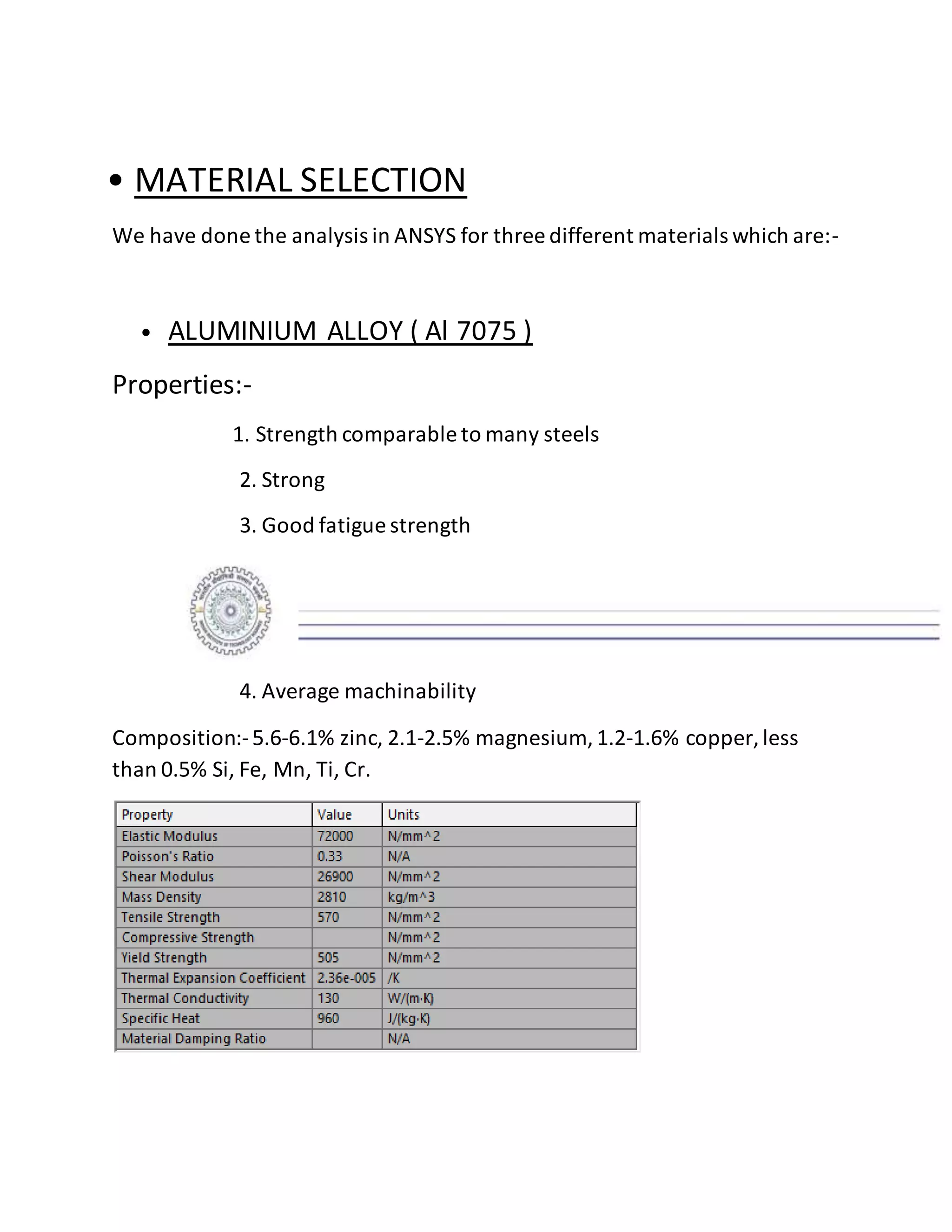
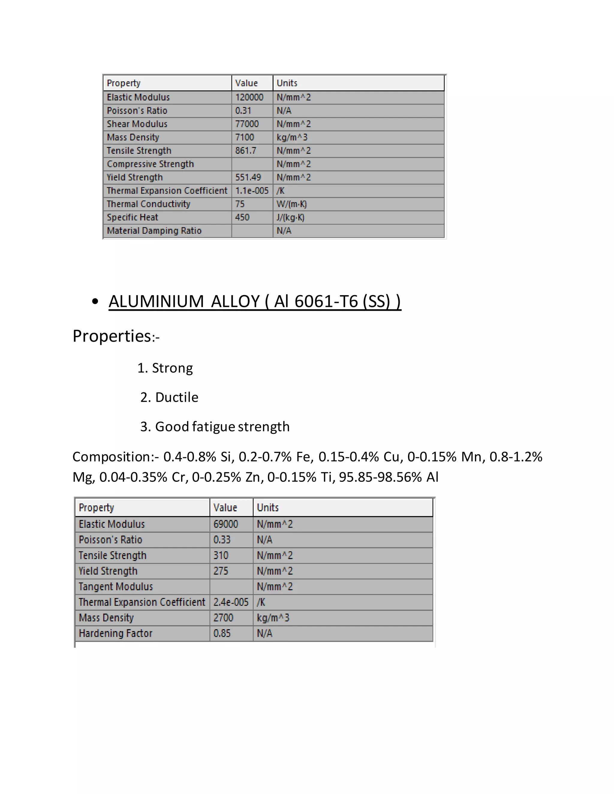
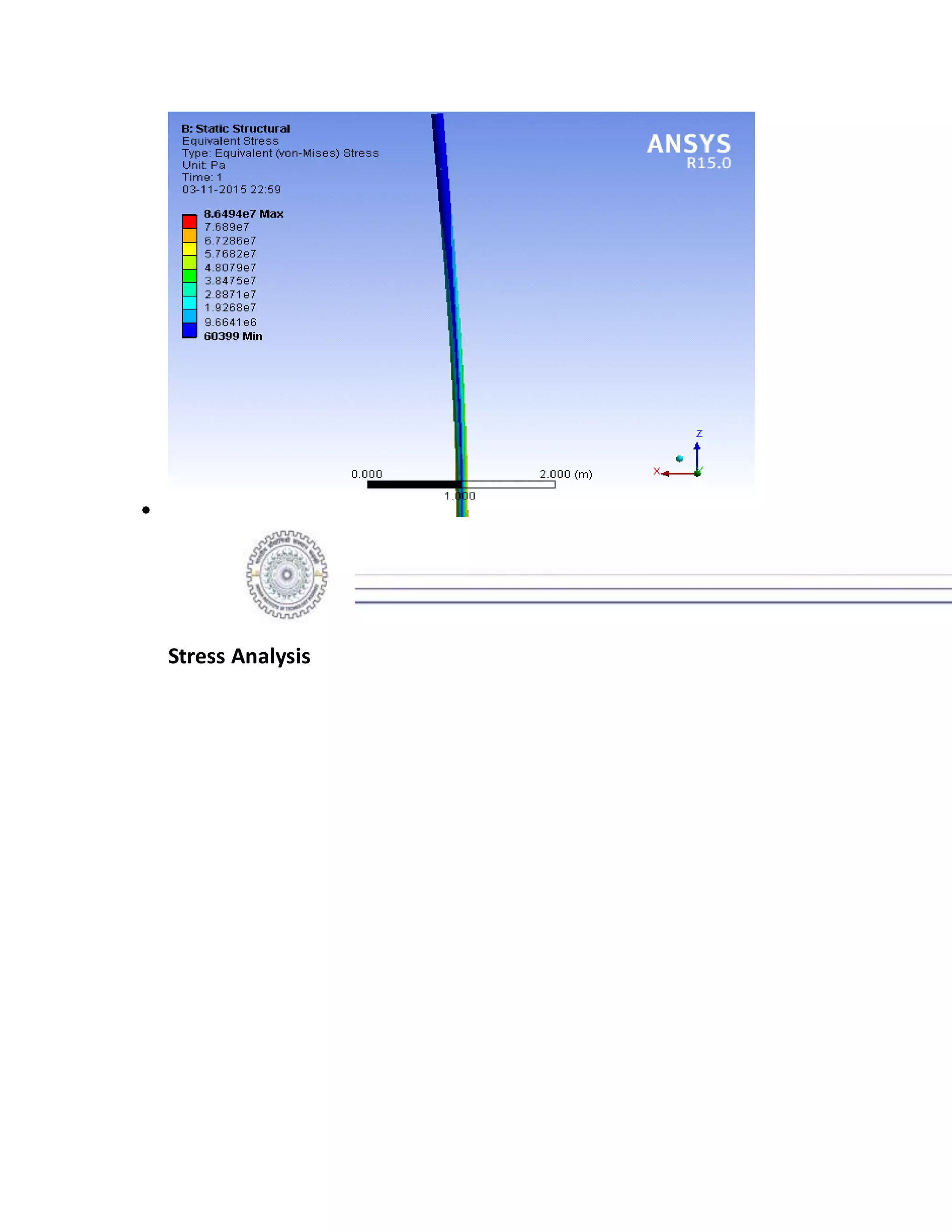
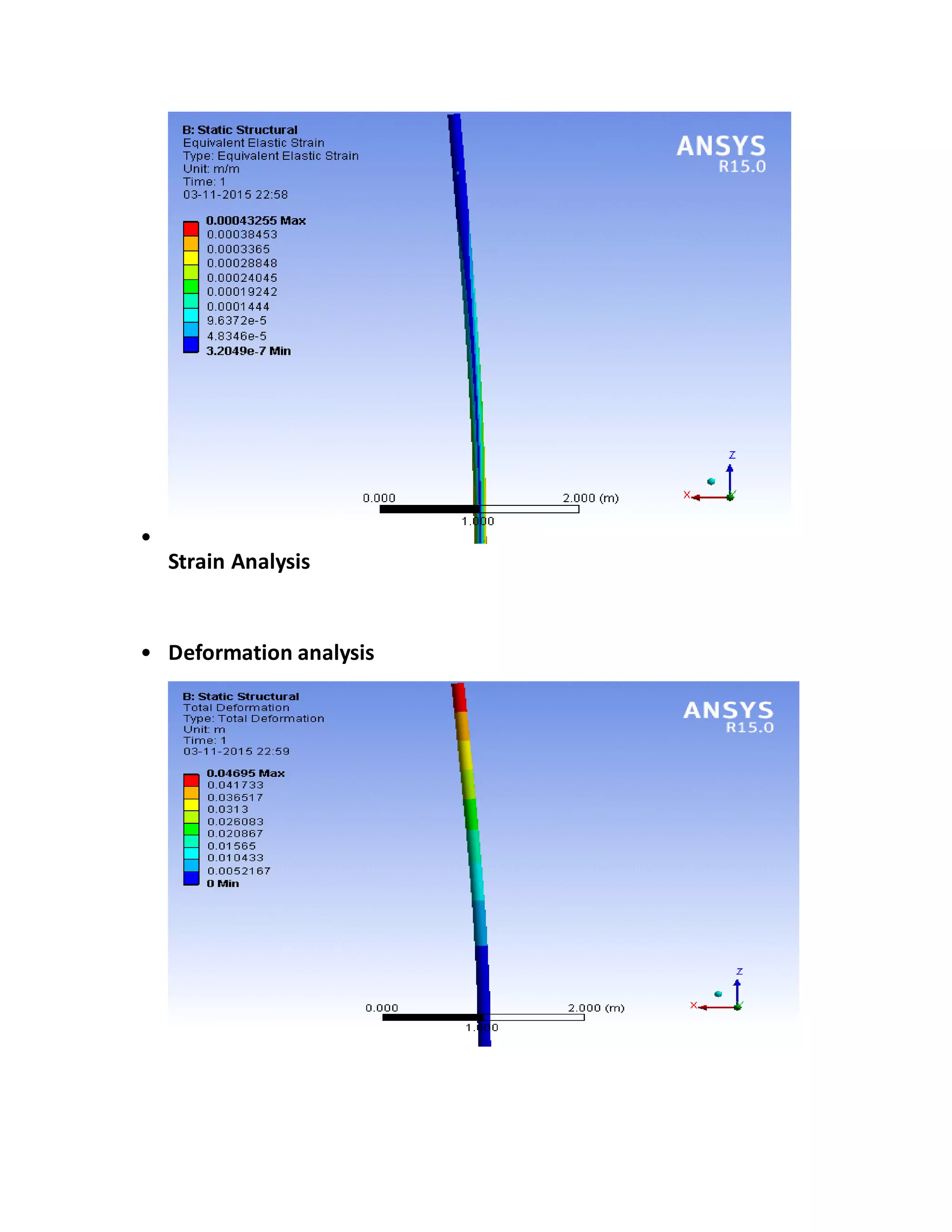
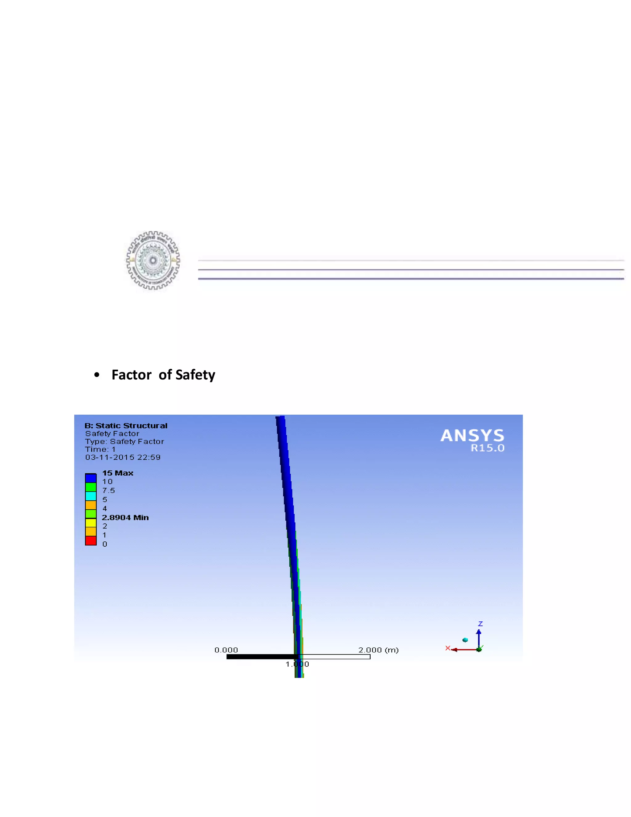
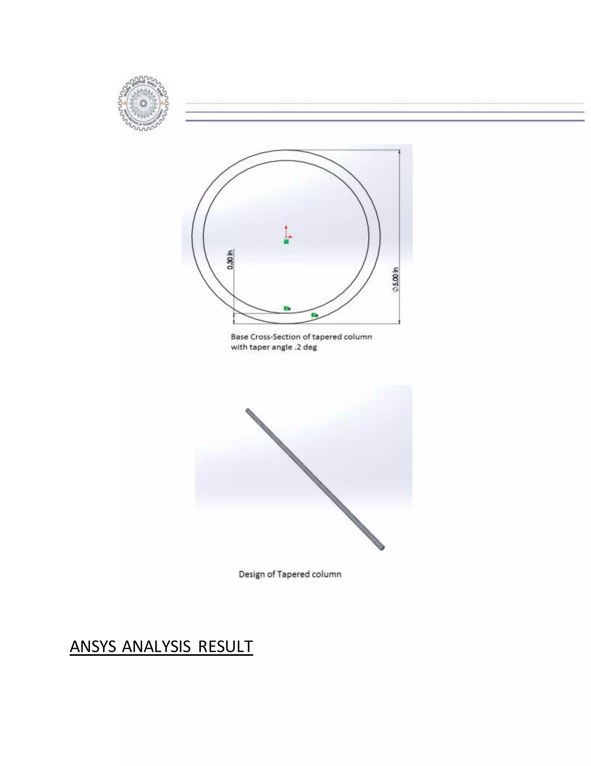
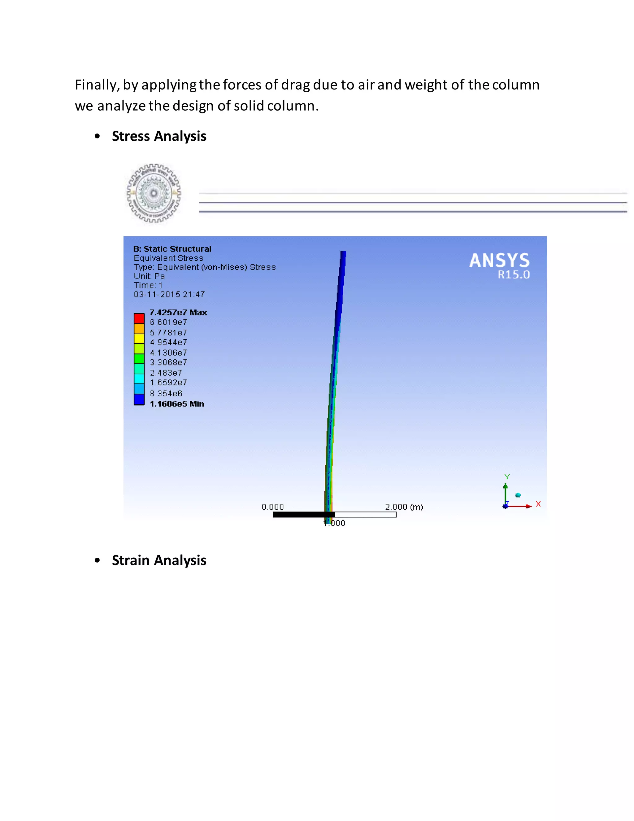
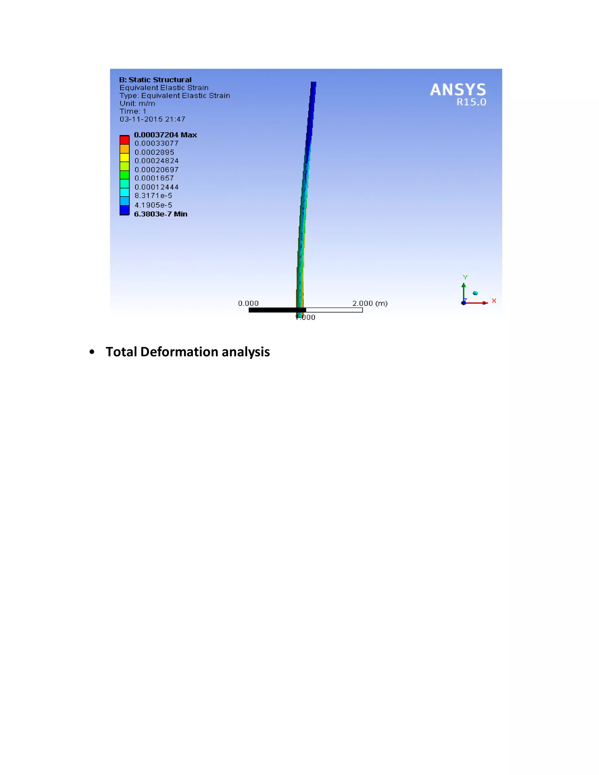
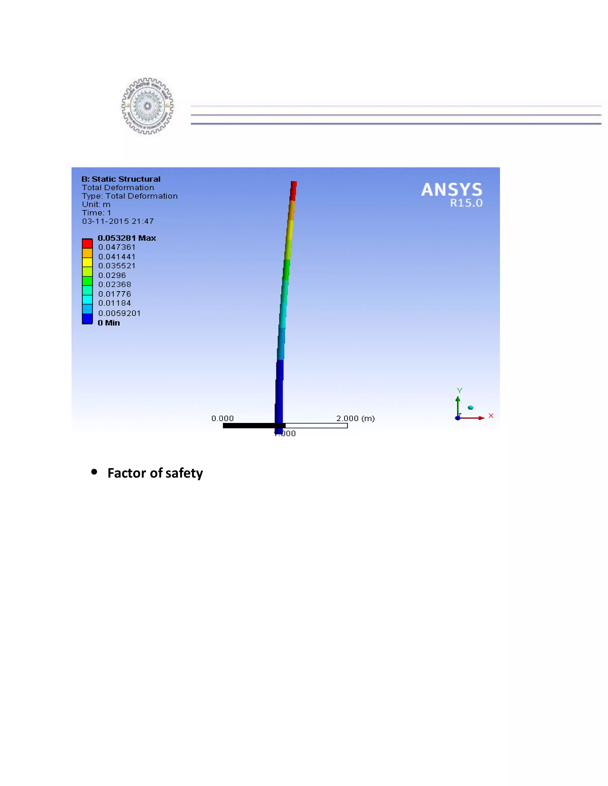
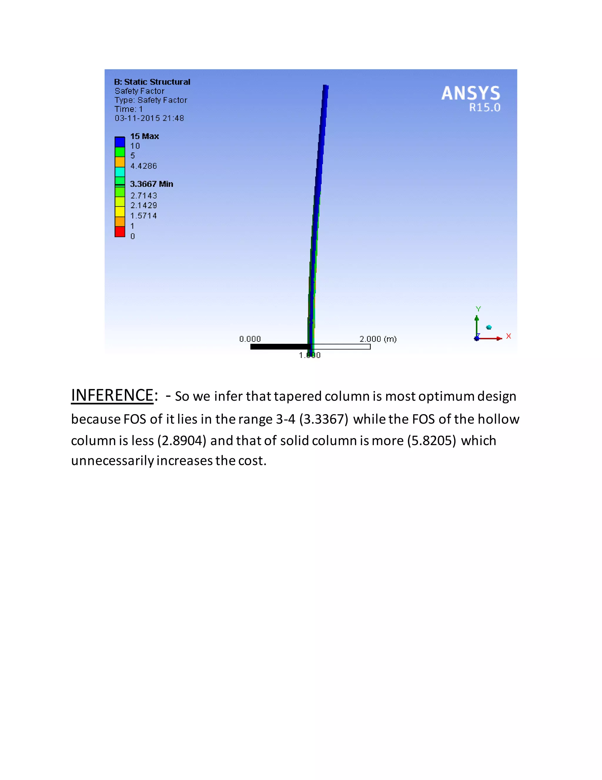
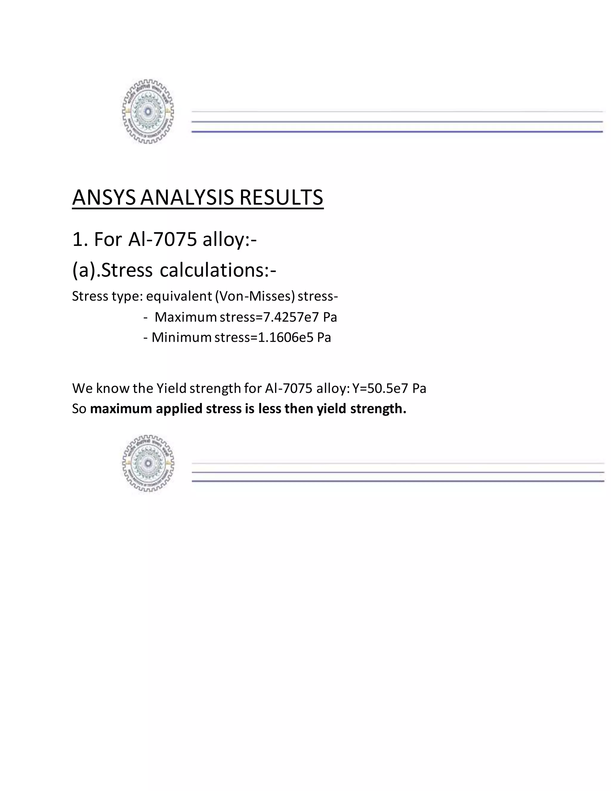
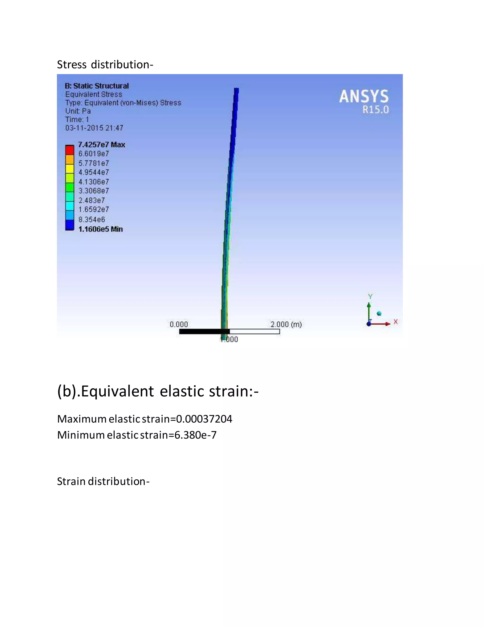
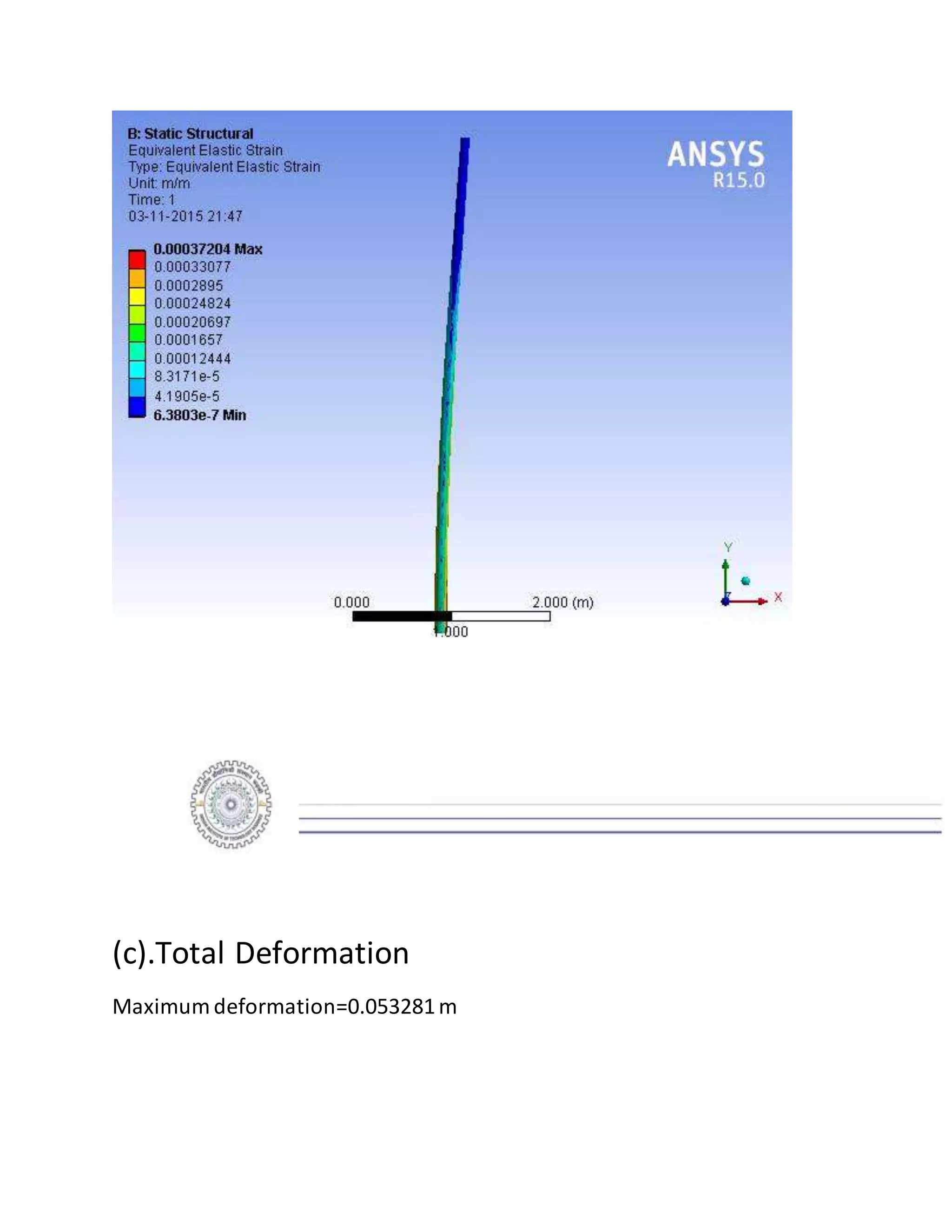
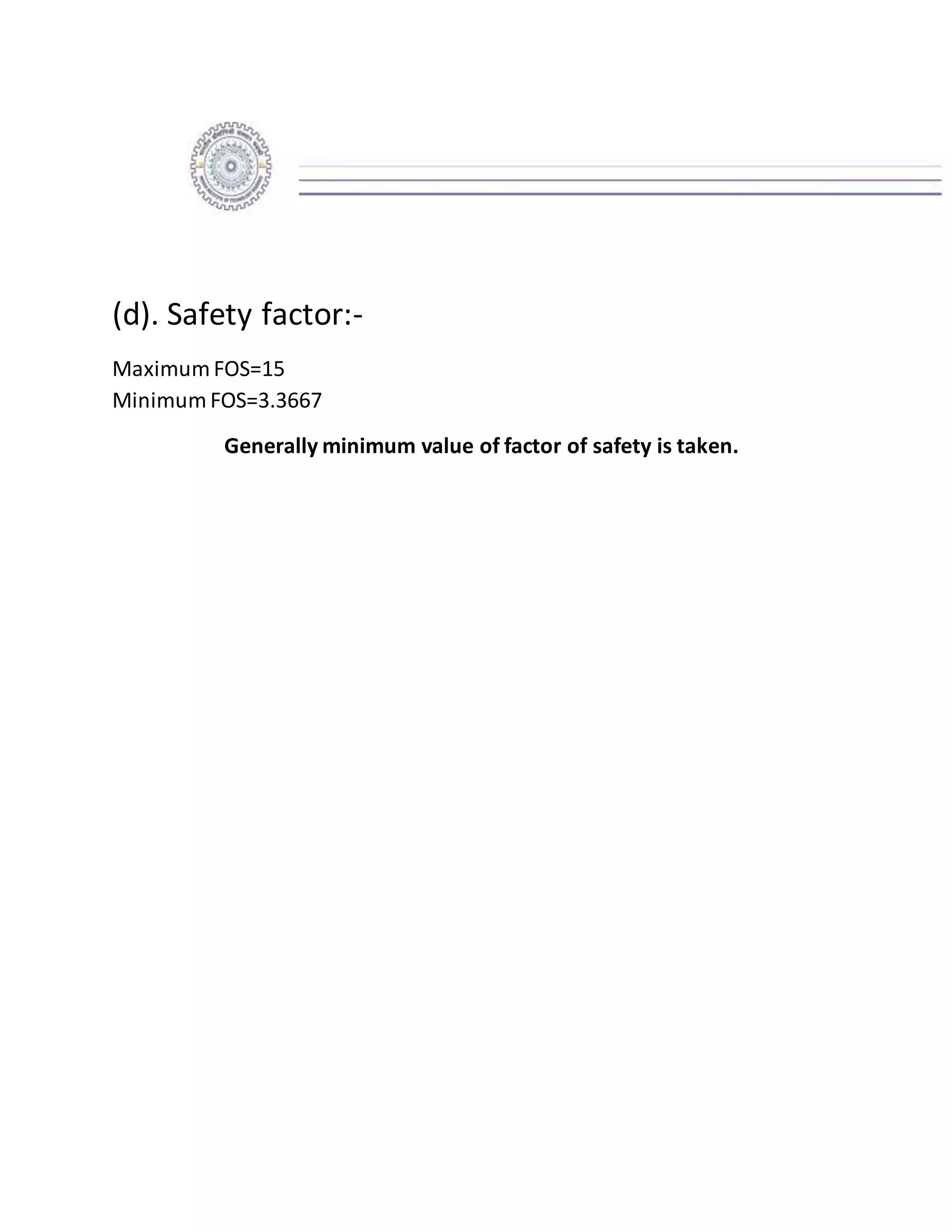
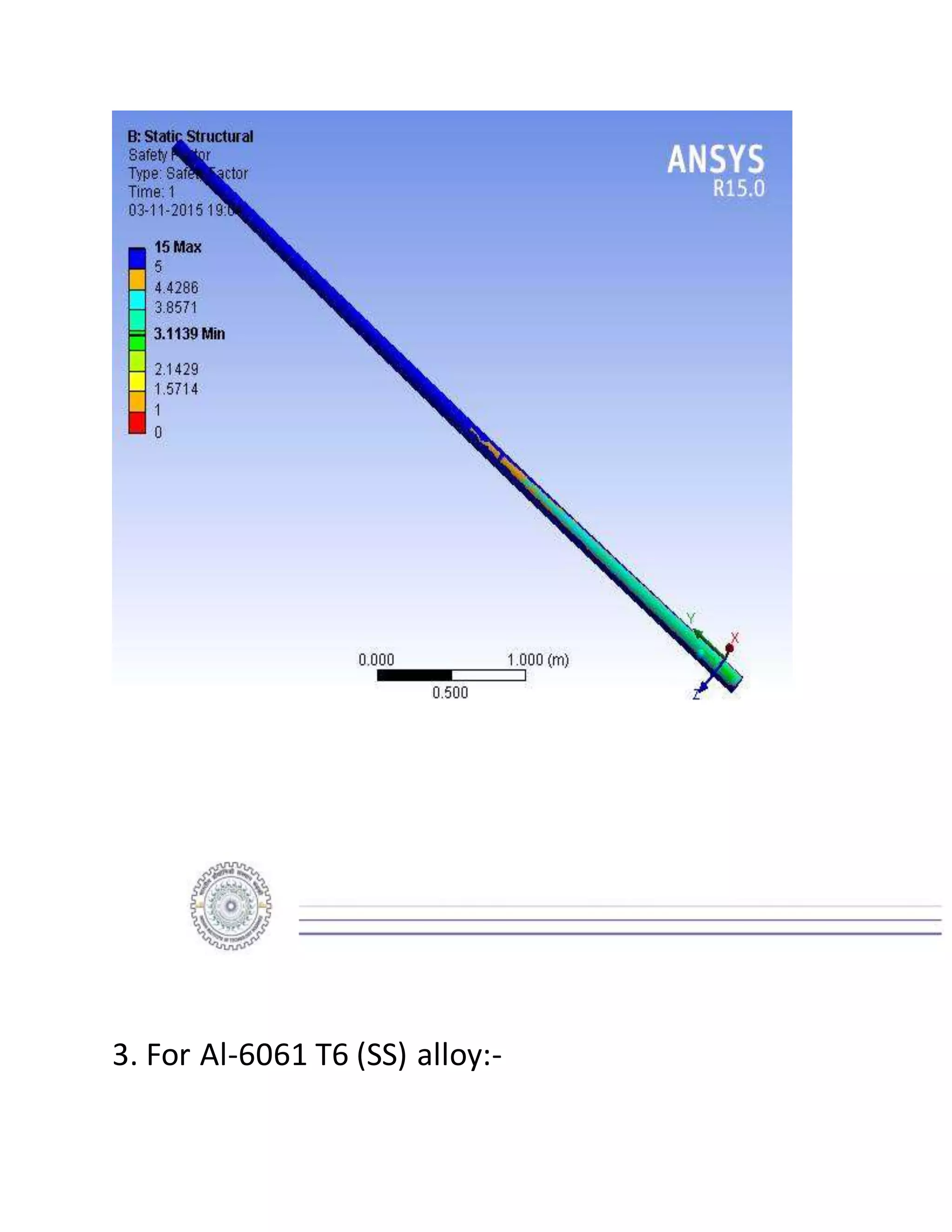
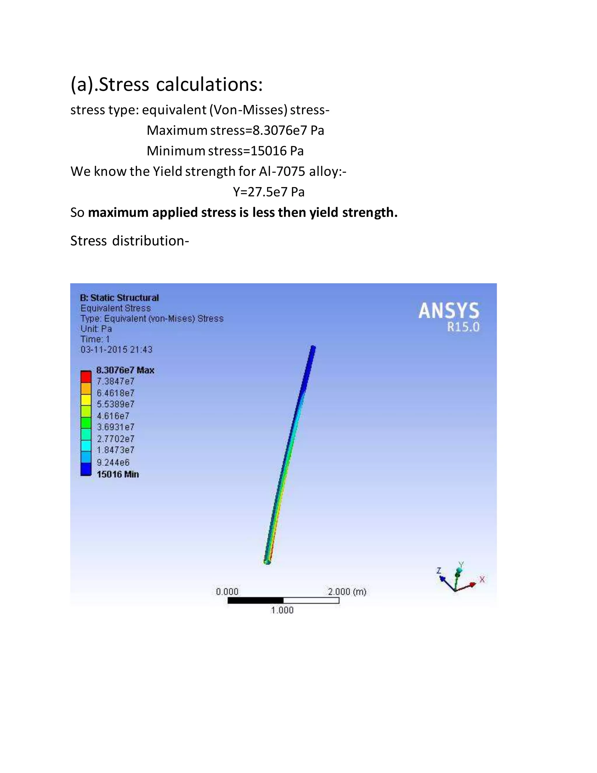
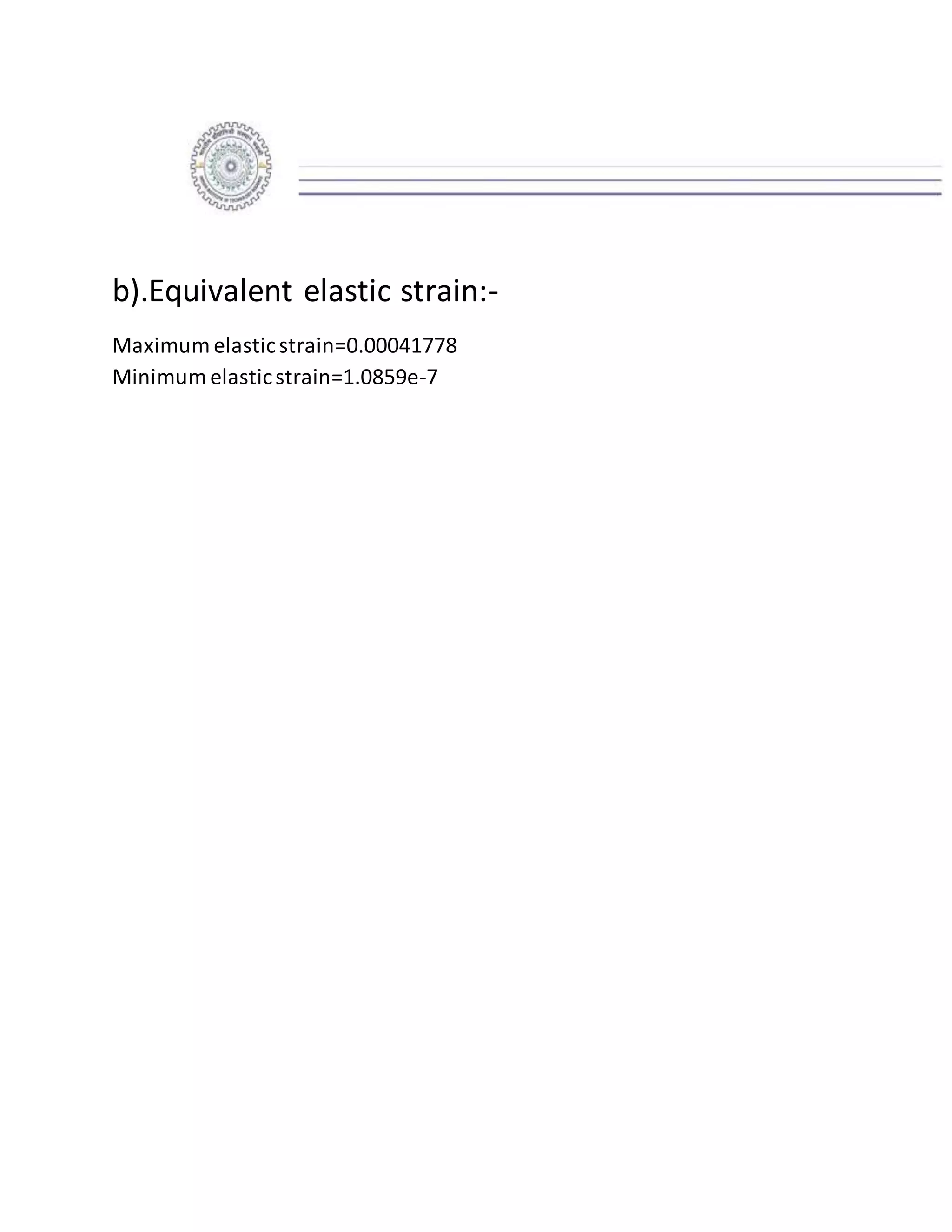
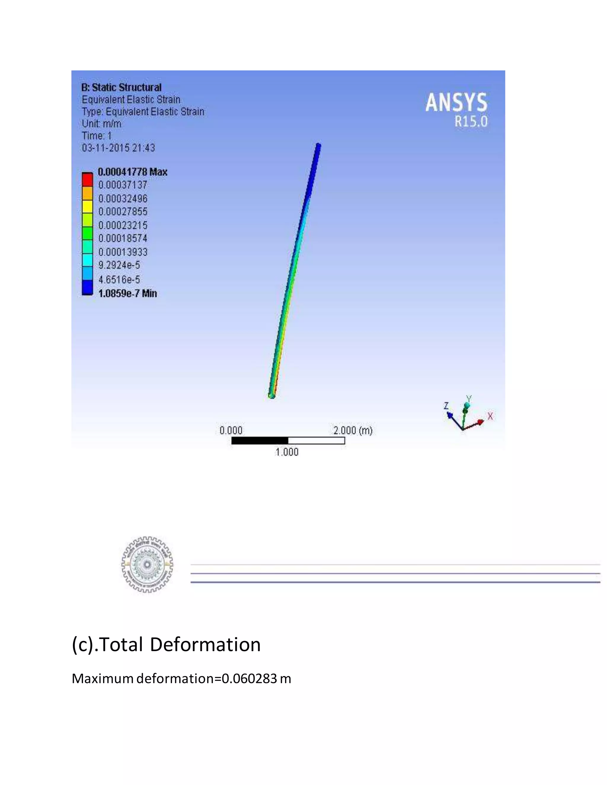
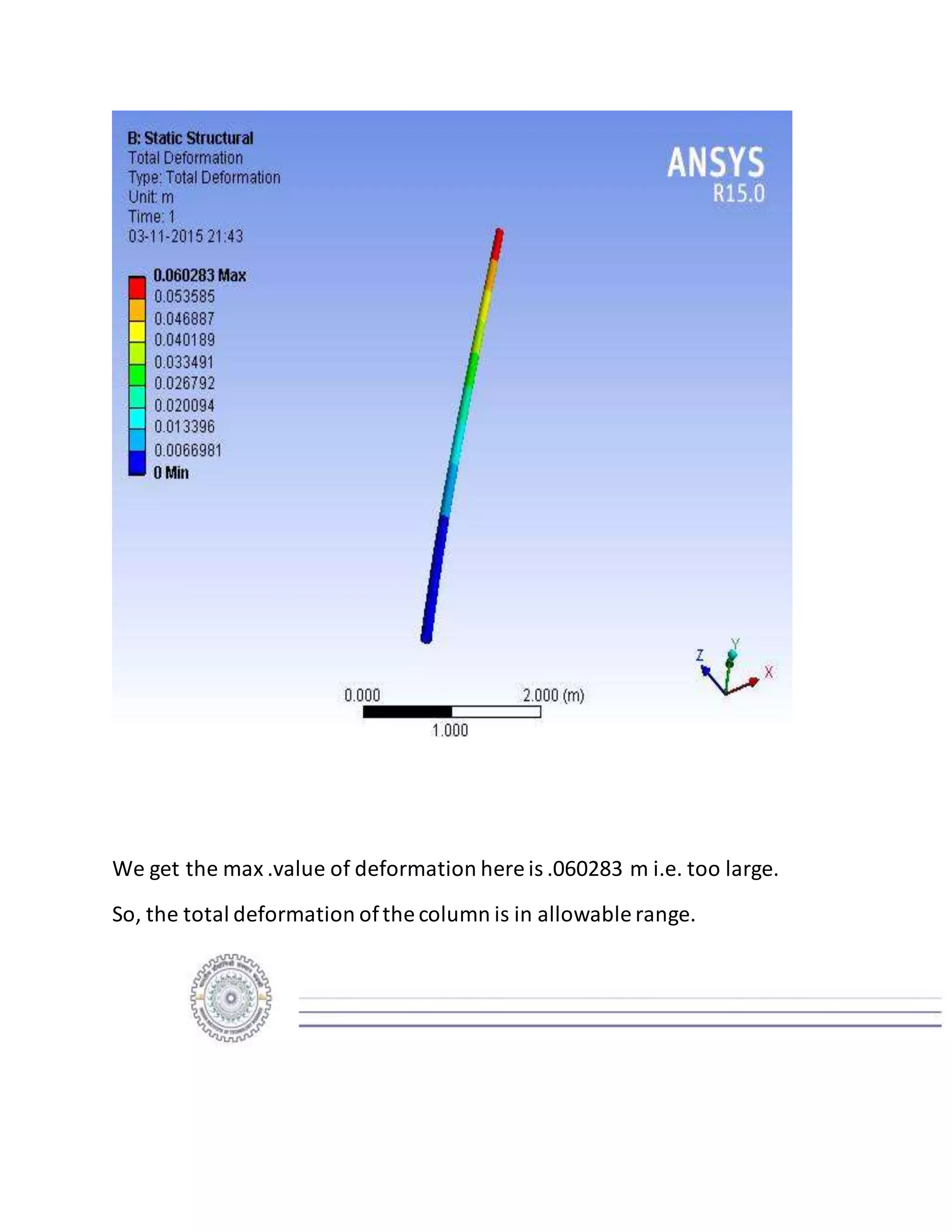
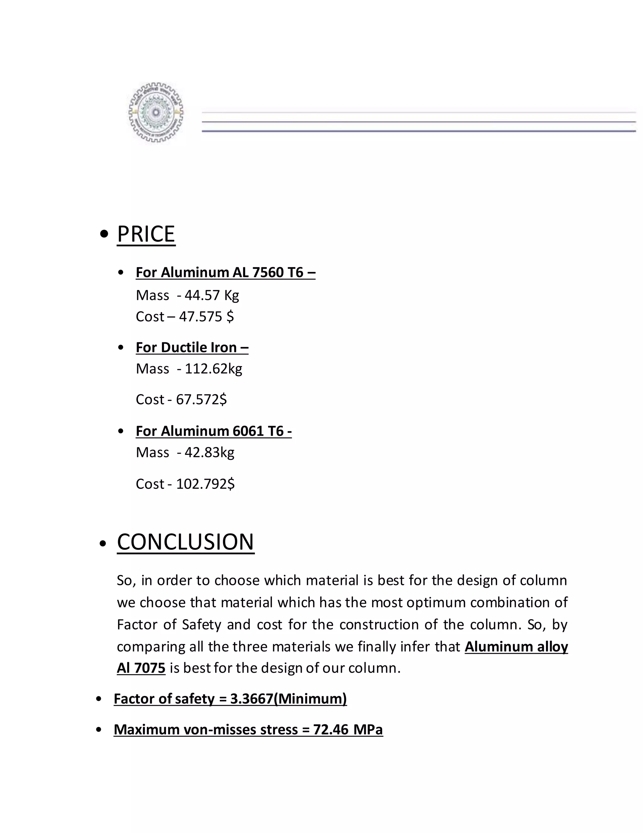
ABSTRACT
Our project report investigates the characteristics or more specifically
design of a column on which a signboard is to be installed at the gate of IIT
ROORKEE. It is a detailed design report for the column with preliminary
calculations, materials selection, solid geometry, stress analysis and cost
estimation. In order to design the column we have considered drag force of
air on the signboard, weight of the signboard and different materials for
making the most optimum design of the column such that it supports the
weight of the signboard and the drag force on the signboard due to air.
Length of the column (5m), dimensions of the signboard (4m*2m*0.05m)
and dead load of the assembly (50kg) is given. For designing the column we
have used the data given to calculate the forces on the column. Also, we
have used software tools like SOLIDWORKS 2014 EDITION for designing the
pole and ANSYS 2015 EDITION for the analysis of the column after
application of the calculated forces. Finally we have summarized the
conclusions of analysis by using ANSYS which includes the material to be
used and the design specifications ofthe pole.
CONTRIBUTION OF GROUP MEMBERS
• SAHIL JINDAL:- Contributed in doing the ANSYS analysis
of the tapered column, hollow column and making of
SOLIDWORKS design .
• KSHITIJ TIWARI:-Contributed in doing the ANSYS
analysis of solid column and making of SOLIDWORKS
design
• MANISH KR. JANGIR:- Contributed in doing the ANSYS
analysis of solid column and making of SOLIDWORKS
design.
• KSHITIZ GAUR:-Contributed in finding the appropriate
materials for the column and making of SOLIDWORKS
design.
Everyone contributed equally in making the report and
final editing and printing of it.
• INTRODUCTION
A Column or pillar in architecture and structural engineering is a structural
element that transmits, through compression, the weight of the structure
above to other structural elements below. Columns are also used to support
structures like signboard, transformers, street lights etc. Columns may be
rectangular, circular, or polygonal in shape; they may taper toward the top
or be of uniform diameter.
Columns are members subjected to combined bending and axial
compression. Their behaviour under uniaxial bending, biaxial bending and
torsional flexural buckling are discussed in this report. A range of behaviour
varying from flexural yielding to torsional flexural or flexural buckling is
possible. In this report evaluation of strength of beam-columns is evaluated
for various materials using ANSYS. The column may fail by reaching either
the ultimate strength of the section (in the case of smaller axial load and
shorter members) or by the buckling strength as governed by weak axis
buckling or lateral torsional buckling. In slender columns with larger axial
compression, either weak axis or lateral torsional buckling would control
failure. The steps in the analysis of strength of column are presented in this
report.
• SOFTWARE TOOLS USED
For the solid geometry development of the column we have used
SOLIDWORKS 2014 EDITION. In solidworks we have designed a hollow
tapered column with some specifications. Then, we calculated the forces
acting on the column due to drag force and weight of the signboard. After
calculation we analyze the column design in ANSYS by feeding the data.
Analysis in ANSYS gives us- total deformation, equivalent stress, equivalent
elastic strain and safety factor. We repeated this process for three different
materials which are generally used for making columns. Finally, we chose
that material that has the most optimum combination of safety factor and
cost of the material.
• ASSUMPTIONS
• The center of mass of the signboard is directly above the
column and no external torque is exerted because of it.
• The material of the column is linearly elastic, homogenous and
isotropic.
• The base of the tower is cantilevered to the ground.
• It is assumed that maximum wind speed is 5m/s
• MATERIAL SELECTION
We have done the analysis in ANSYS for three different materials which are:-
• ALUMINIUM ALLOY ( Al 7075 )
Properties:-
1. Strength comparable to many steels
2. Strong
3. Good fatigue strength
4. Average machinability
Composition:-5.6-6.1% zinc, 2.1-2.5% magnesium, 1.2-1.6% copper, less
than 0.5% Si, Fe, Mn, Ti, Cr.
• DUCTILE IRON
Properties:-
1. Ductile
2. Fatigue resistance
3. Hard
Composition:- 3.2-3.6% carbon, 2.2-2.8% silicon, 0.1-0.5% manganese, 0.03-
0.05% magnesium, 0.005-0.04% phosphorous, 0.005-0.02% sulphur, less
than 0.4% copper, Iron -balance.
• ALUMINIUM ALLOY ( Al 6061-T6 (SS) )
Properties:-
1. Strong
2. Ductile
3. Good fatigue strength
Composition:- 0.4-0.8% Si, 0.2-0.7% Fe, 0.15-0.4% Cu, 0-0.15% Mn, 0.8-1.2%
Mg, 0.04-0.35% Cr, 0-0.25% Zn, 0-0.15% Ti, 95.85-98.56% Al
Applied Forces
(fixed for all 3 materials)
• On the top of surface area F1= Weight of signboard
=490.5N (AlongY-axis)
• Drag force on sign board =1812.6N (AlongX-axis)
• Weight of pole act at the centre of mass of the pole.
• Fixed at the bottom.
• SELECTION OF DESIGN OF THE COLUMN
We have selected three column designs for analysis which are-
• Solid bar
• Hollow uniform column
• Tapered uniform column
• SOLID GEOMETRY DEVELOPMENT
We have made the solidworks model of all the three designs. For solid
geometry development we used SOLIDWORKS 2014 version.
• HOLLOW COLUMN
We have made the solidworks model of hollowcolumn with certain
specifications as follows:-
ANSYS ANALYSIS RESULT
Finally,by applyingthe forces due to drag we analyze the hollowcolumn
design in ANSYS.
•
Stress Analysis
•
Strain Analysis
• Deformation analysis
• Factor of Safety
• SOLID COLUMN
We have made the solidworks model of
solid column with certain specifications as follows:-
ANSYS ANALYSIS RESULT
Finally,by applyingthe forces of drag due to airand weight of the column
we analyze the design of solid column.
•
Stress Analysis
•
Strain Analysis
• Deformation analysis
•
Factor of safety
• HOLLOW TAPERED COLUMN
We have made the solidworks model of solid column with certain
specifications as follows:-
ANSYS ANALYSIS RESULT
Finally,by applyingthe forces of drag due to airand weight of the column
we analyze the design of solid column.
• Stress Analysis
• Strain Analysis
• Total Deformation analysis
• Factor of safety
INFERENCE: - So we infer that tapered column is most optimum design
because FOS of it lies in the range 3-4 (3.3367) while the FOS of the hollow
column is less (2.8904) and that of solid column is more (5.8205) which
unnecessarilyincreases the cost.
ANSYS ANALYSIS RESULTS
1. For Al-7075 alloy:-
(a).Stress calculations:-
Stress type: equivalent (Von-Misses)stress-
- Maximum stress=7.4257e7 Pa
- Minimum stress=1.1606e5 Pa
We know the Yield strength for Al-7075 alloy:Y=50.5e7 Pa
So maximum applied stress is less then yield strength.
Stress distribution-
(b).Equivalent elastic strain:-
Maximum elasticstrain=0.00037204
Minimum elasticstrain=6.380e-7
Strain distribution-
(c).Total Deformation
Maximum deformation=0.053281m
As deformation occurs,internal inter-molecularforces arise that oppose the
applied force.If the applied force is not too great these forces may be
sufficient to completelyresist the applied force and allowthe object to
assume a new equilibrium state and to return to its original state when the
load is removed.A larger applied force may lead to a permanent
deformation ofthe object or even to its structural failure.
But we get the max .value of deformation here is .053281 m i.e. too large.
So, the total deformation ofthe column is in allowable range.
(d). Safety Factor:-
Maximum FOS=15
Minimum FOS=3.3667
(Generallyminimum value of factorof safetyis taken.)
The value of factor of safety for the optimum design should lies b/w2-4
& and we get the value n=3.3667.
2. For Ductile iron:-
(a).Stress calculations:
Stress type: equivalent (Von-Misses)stress-
Maximum stress=8.0285e7 Pa
Minimum stress= 96648Pa
We know the Yield strength for Ductile iron alloy:-
Y=55.149e7Pa
So maximum applied stress is less then yield strength.
Stress distribution-
b).Equivalent elastic strain:-
Maximum elasticstrain=0.00040224
Minimum elasticstrain=6.5314e-7
(c).Total Deformation
Maximum deformation=0.061185m
.
We get the max .value of deformation here is .061185m i.e. too large.
So, the total deformation ofthe column is in allowable range.
(d). Safety factor:-
Maximum FOS=15
Minimum FOS=3.3667
Generally minimum value of factor of safety is taken.
3. For Al-6061 T6 (SS) alloy:-
(a).Stress calculations:
stress type: equivalent (Von-Misses)stress-
Maximum stress=8.3076e7 Pa
Minimum stress=15016 Pa
We know the Yield strength for Al-7075 alloy:-
Y=27.5e7 Pa
So maximum applied stress is less then yield strength.
Stress distribution-
b).Equivalent elastic strain:-
Maximum elasticstrain=0.00041778
Minimum elasticstrain=1.0859e-7
(c).Total Deformation
Maximum deformation=0.060283m
We get the max .value of deformation here is .060283 m i.e. too large.
So, the total deformation ofthe column is in allowable range.
(d). Safety factor:-
Maximum FOS=15
Minimum FOS=3.0093
Generally minimum value of factor of safety is taken.
• PRICE
• For Aluminum AL 7560 T6 –
Mass - 44.57 Kg
Cost – 47.575 $
• For Ductile Iron –
Mass - 112.62kg
Cost - 67.572$
• For Aluminum 6061 T6 -
Mass - 42.83kg
Cost - 102.792$
• CONCLUSION
So, in order to choose which material is best for the design of column
we choose that material which has the most optimum combination of
Factor of Safety and cost for the construction of the column. So, by
comparing all the three materials we finally infer that Aluminum alloy
Al 7075 is best for the design of our column.
• Factor of safety = 3.3667(Minimum)
• Maximum von-misses stress = 72.46 MPa
• Material = Aluminum alloy Al 7075
• Total Cost = 47.575 $
• BIBLIOGRAPHY
• www.alibaba.com
• www.wikipedia.com
• www.youtube.comAnsys-point-force
• http://www.hawkridgesys.com/blog/quality-control-type-mesh-ansys/
• www.quora.com
• http://help.ansys.com/2015/English/ansys/cworks/c_Solid_Mesh.htm
• http://help.ansys.com/2014/English/ansys/cworks/c_Mesh_Contr
ol_Parameters.htm
• http://www.roymech.co.uk/Useful_Tables/Matter/Costs.html as in
2014

Project for Design of a Signboard Column

  • 3.
    ABSTRACT Our project reportinvestigates the characteristics or more specifically design of a column on which a signboard is to be installed at the gate of IIT ROORKEE. It is a detailed design report for the column with preliminary calculations, materials selection, solid geometry, stress analysis and cost estimation. In order to design the column we have considered drag force of air on the signboard, weight of the signboard and different materials for making the most optimum design of the column such that it supports the weight of the signboard and the drag force on the signboard due to air. Length of the column (5m), dimensions of the signboard (4m*2m*0.05m) and dead load of the assembly (50kg) is given. For designing the column we have used the data given to calculate the forces on the column. Also, we have used software tools like SOLIDWORKS 2014 EDITION for designing the pole and ANSYS 2015 EDITION for the analysis of the column after application of the calculated forces. Finally we have summarized the conclusions of analysis by using ANSYS which includes the material to be used and the design specifications ofthe pole.
  • 4.
    CONTRIBUTION OF GROUPMEMBERS • SAHIL JINDAL:- Contributed in doing the ANSYS analysis of the tapered column, hollow column and making of SOLIDWORKS design . • KSHITIJ TIWARI:-Contributed in doing the ANSYS analysis of solid column and making of SOLIDWORKS design • MANISH KR. JANGIR:- Contributed in doing the ANSYS analysis of solid column and making of SOLIDWORKS design. • KSHITIZ GAUR:-Contributed in finding the appropriate materials for the column and making of SOLIDWORKS design. Everyone contributed equally in making the report and final editing and printing of it.
  • 5.
    • INTRODUCTION A Columnor pillar in architecture and structural engineering is a structural element that transmits, through compression, the weight of the structure above to other structural elements below. Columns are also used to support structures like signboard, transformers, street lights etc. Columns may be rectangular, circular, or polygonal in shape; they may taper toward the top or be of uniform diameter. Columns are members subjected to combined bending and axial compression. Their behaviour under uniaxial bending, biaxial bending and torsional flexural buckling are discussed in this report. A range of behaviour varying from flexural yielding to torsional flexural or flexural buckling is possible. In this report evaluation of strength of beam-columns is evaluated for various materials using ANSYS. The column may fail by reaching either the ultimate strength of the section (in the case of smaller axial load and shorter members) or by the buckling strength as governed by weak axis buckling or lateral torsional buckling. In slender columns with larger axial compression, either weak axis or lateral torsional buckling would control
  • 6.
    failure. The stepsin the analysis of strength of column are presented in this report. • SOFTWARE TOOLS USED For the solid geometry development of the column we have used SOLIDWORKS 2014 EDITION. In solidworks we have designed a hollow tapered column with some specifications. Then, we calculated the forces acting on the column due to drag force and weight of the signboard. After calculation we analyze the column design in ANSYS by feeding the data. Analysis in ANSYS gives us- total deformation, equivalent stress, equivalent elastic strain and safety factor. We repeated this process for three different materials which are generally used for making columns. Finally, we chose that material that has the most optimum combination of safety factor and cost of the material. • ASSUMPTIONS • The center of mass of the signboard is directly above the column and no external torque is exerted because of it. • The material of the column is linearly elastic, homogenous and isotropic. • The base of the tower is cantilevered to the ground. • It is assumed that maximum wind speed is 5m/s
  • 7.
    • MATERIAL SELECTION Wehave done the analysis in ANSYS for three different materials which are:- • ALUMINIUM ALLOY ( Al 7075 ) Properties:- 1. Strength comparable to many steels 2. Strong 3. Good fatigue strength 4. Average machinability Composition:-5.6-6.1% zinc, 2.1-2.5% magnesium, 1.2-1.6% copper, less than 0.5% Si, Fe, Mn, Ti, Cr.
  • 8.
    • DUCTILE IRON Properties:- 1.Ductile 2. Fatigue resistance 3. Hard Composition:- 3.2-3.6% carbon, 2.2-2.8% silicon, 0.1-0.5% manganese, 0.03- 0.05% magnesium, 0.005-0.04% phosphorous, 0.005-0.02% sulphur, less than 0.4% copper, Iron -balance.
  • 9.
    • ALUMINIUM ALLOY( Al 6061-T6 (SS) ) Properties:- 1. Strong 2. Ductile 3. Good fatigue strength Composition:- 0.4-0.8% Si, 0.2-0.7% Fe, 0.15-0.4% Cu, 0-0.15% Mn, 0.8-1.2% Mg, 0.04-0.35% Cr, 0-0.25% Zn, 0-0.15% Ti, 95.85-98.56% Al
  • 10.
    Applied Forces (fixed forall 3 materials) • On the top of surface area F1= Weight of signboard =490.5N (AlongY-axis) • Drag force on sign board =1812.6N (AlongX-axis) • Weight of pole act at the centre of mass of the pole. • Fixed at the bottom.
  • 11.
    • SELECTION OFDESIGN OF THE COLUMN We have selected three column designs for analysis which are- • Solid bar
  • 12.
    • Hollow uniformcolumn • Tapered uniform column • SOLID GEOMETRY DEVELOPMENT We have made the solidworks model of all the three designs. For solid geometry development we used SOLIDWORKS 2014 version. • HOLLOW COLUMN We have made the solidworks model of hollowcolumn with certain specifications as follows:-
  • 13.
    ANSYS ANALYSIS RESULT Finally,byapplyingthe forces due to drag we analyze the hollowcolumn design in ANSYS.
  • 14.
  • 15.
  • 16.
  • 17.
    • SOLID COLUMN Wehave made the solidworks model of solid column with certain specifications as follows:-
  • 18.
    ANSYS ANALYSIS RESULT Finally,byapplyingthe forces of drag due to airand weight of the column we analyze the design of solid column.
  • 19.
  • 20.
  • 21.
    • Factor of safety •HOLLOW TAPERED COLUMN We have made the solidworks model of solid column with certain specifications as follows:-
  • 22.
  • 23.
    Finally,by applyingthe forcesof drag due to airand weight of the column we analyze the design of solid column. • Stress Analysis • Strain Analysis
  • 24.
  • 25.
  • 26.
    INFERENCE: - Sowe infer that tapered column is most optimum design because FOS of it lies in the range 3-4 (3.3367) while the FOS of the hollow column is less (2.8904) and that of solid column is more (5.8205) which unnecessarilyincreases the cost.
  • 27.
    ANSYS ANALYSIS RESULTS 1.For Al-7075 alloy:- (a).Stress calculations:- Stress type: equivalent (Von-Misses)stress- - Maximum stress=7.4257e7 Pa - Minimum stress=1.1606e5 Pa We know the Yield strength for Al-7075 alloy:Y=50.5e7 Pa So maximum applied stress is less then yield strength.
  • 28.
    Stress distribution- (b).Equivalent elasticstrain:- Maximum elasticstrain=0.00037204 Minimum elasticstrain=6.380e-7 Strain distribution-
  • 29.
  • 30.
    As deformation occurs,internalinter-molecularforces arise that oppose the applied force.If the applied force is not too great these forces may be sufficient to completelyresist the applied force and allowthe object to assume a new equilibrium state and to return to its original state when the load is removed.A larger applied force may lead to a permanent deformation ofthe object or even to its structural failure. But we get the max .value of deformation here is .053281 m i.e. too large. So, the total deformation ofthe column is in allowable range.
  • 31.
    (d). Safety Factor:- MaximumFOS=15 Minimum FOS=3.3667 (Generallyminimum value of factorof safetyis taken.) The value of factor of safety for the optimum design should lies b/w2-4 & and we get the value n=3.3667.
  • 32.
    2. For Ductileiron:- (a).Stress calculations: Stress type: equivalent (Von-Misses)stress- Maximum stress=8.0285e7 Pa Minimum stress= 96648Pa We know the Yield strength for Ductile iron alloy:- Y=55.149e7Pa So maximum applied stress is less then yield strength. Stress distribution-
  • 33.
    b).Equivalent elastic strain:- Maximumelasticstrain=0.00040224 Minimum elasticstrain=6.5314e-7
  • 34.
  • 35.
    . We get themax .value of deformation here is .061185m i.e. too large. So, the total deformation ofthe column is in allowable range.
  • 36.
    (d). Safety factor:- MaximumFOS=15 Minimum FOS=3.3667 Generally minimum value of factor of safety is taken.
  • 37.
    3. For Al-6061T6 (SS) alloy:-
  • 38.
    (a).Stress calculations: stress type:equivalent (Von-Misses)stress- Maximum stress=8.3076e7 Pa Minimum stress=15016 Pa We know the Yield strength for Al-7075 alloy:- Y=27.5e7 Pa So maximum applied stress is less then yield strength. Stress distribution-
  • 39.
    b).Equivalent elastic strain:- Maximumelasticstrain=0.00041778 Minimum elasticstrain=1.0859e-7
  • 40.
  • 41.
    We get themax .value of deformation here is .060283 m i.e. too large. So, the total deformation ofthe column is in allowable range.
  • 42.
    (d). Safety factor:- MaximumFOS=15 Minimum FOS=3.0093 Generally minimum value of factor of safety is taken.
  • 43.
    • PRICE • ForAluminum AL 7560 T6 – Mass - 44.57 Kg Cost – 47.575 $ • For Ductile Iron – Mass - 112.62kg Cost - 67.572$ • For Aluminum 6061 T6 - Mass - 42.83kg Cost - 102.792$ • CONCLUSION So, in order to choose which material is best for the design of column we choose that material which has the most optimum combination of Factor of Safety and cost for the construction of the column. So, by comparing all the three materials we finally infer that Aluminum alloy Al 7075 is best for the design of our column. • Factor of safety = 3.3667(Minimum) • Maximum von-misses stress = 72.46 MPa
  • 44.
    • Material =Aluminum alloy Al 7075 • Total Cost = 47.575 $ • BIBLIOGRAPHY • www.alibaba.com • www.wikipedia.com • www.youtube.comAnsys-point-force • http://www.hawkridgesys.com/blog/quality-control-type-mesh-ansys/ • www.quora.com • http://help.ansys.com/2015/English/ansys/cworks/c_Solid_Mesh.htm • http://help.ansys.com/2014/English/ansys/cworks/c_Mesh_Contr ol_Parameters.htm
  • 45.